
SFH331_01 OSRAM
Document overview
- Manufacturer or author: Provided By www.digicamel.com(FREE DATASHEET DOWNLOAD SITE)
- PDF pages: 8
Technical content
Features
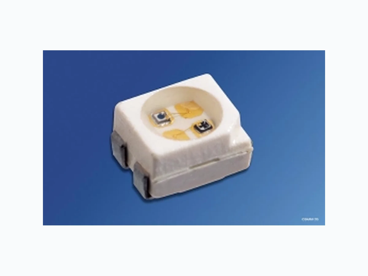
SMT package with red emitter (635 nm) and Si-phototransistor Suitable for SMT assembly Available on tape and reel Emitter and detector can be controlled separately Suitable for IR-reflow soldering
Applications
Data transmission Lock bar Infrared interface
Note: Die angegebenen Grenzdaten gelten für den Chip, für den sie angegeben sind, unabhängig vom Betriebszustand des anderen. The stated max. ratings refer to the specified chip regardless of the operating status of the other one. Grenzwerte Maximum Ratings Bezeichnung Parameter Symbol Symbol Wert Value Einheit Unit LED Transistor Betriebstemperatur Operating temperature range Top – 40 … + 100 – 40 … + 100 °C Lagertemperatur Storage temperature range Tstg – 40 … + 100 – 40 … + 100 °C Sperrschichttemperatur Junction temperature Tj + 100 + 100 °C Durchlaßstrom (LED) Forward current (LED) IF 30 – mA Kollektorstrom (Transistor) Collector current (Transistor) IC – 15 mA Stoßstrom Surge current t ≤ 10 µs, D = 0.005 IFM 500 75 mA Sperrspannung (LED) Reverse voltage (LED) VR 5 – V Kollektor-Emitter Spannung (Transistor) Collector-emitter voltage (Transistor) VCE – 35 V Verlustleistung Power dissipation Ptot 100 165 mW W ärmewiderstand Sperrschicht/Umgebung Thermal resistance junction/ambient Montage auf PC-Board1) (Padgröße ≥ 16 mm2) mounting on pcb1) (pad size ≥ 16 mm2) Sperrschicht / Lötstelle junction / soldering joint RthJA RthJS 450 350 450 K/W K/W 1) PC-board: G30/FR4
Kennwerte LED (TA = 25 °C) Characteristics LED Bezeichnung Parameter Symbol Symbol Wert Value Einheit Unit Wellenlänge des emittierten Lichtes (typ.) Wavelength at peak emission (typ.) IF = 10 mA λpeak 635 nm Dominantwellenlänge (typ.) Dominant wavelength (typ.) IF = 10 mA λdom 628 nm Spektrale Bandbreite bei 50% von Irel max (typ.) Spectral bandwidth at 50% of Irel max (typ.) IF = 10 mA ∆λ 45 nm Abstrahlwinkel bei 50% von IV (Vollwinkel) Viewing angle at 50% of IV 2ϕ 120 Grad deg. Durchlaßspannung (typ.) Forward voltage (max.) IF = 10 mA VF VF 2.0 2.6 V V Sperrstrom (typ.) Reverse current (max) VR = 5 V IR IR 0.01 µA µA Kapazität, (typ.) Capacitance VR = 0 V, f = 1 MHz C o 12 pF Schaltzeiten: Switching times: I V from 10% to 90% (typ.) IV from 90% to 10% (typ.) IF = 100 mA, tp = 10 µs, RL = 50 Ω tr tf 300 150 ns ns Lichtstärke (Gruppe JK) (typ.) Luminous intensity (group JK) IF = 10 mA IV 6 (4.0 … 12.5) mcd
Kennwerte Fototransistor (TA = 25 °C, λ= 950 nm) Characteristics Phototransistor Bezeichnung Parameter Symbol Symbol Wert Value Einheit Unit Wellenlänge der max. Fotoempfindlichkeit Wavelength of max. sensitivity λSm a x 860 nm Spektraler Bereich der Fotoempfindlichkeit S = 10% von Smax Spectral range of sensitivity S = 10% of Smax λ 380 … 1150 nm Bestrahlungsempfindliche Fläche (∅ 240 µm) Radiant sensitive area (∅ 240 µm) A 0.045 mm 2 Abmessungen der Chipfläche Dimensions of chip area L × B 0.45× 0.45 mm × mm Abstand Chipoberfläche zu Gehäuseoberfläche Distance chip surface to case surface H 0.5… 0.7 mm Halbwinkel Half angle ϕ± 60 Grad deg. Kapazität Capacitance VCE = 0 V, f = 1 MHz, E = 0 C CE 5.0 pF Dunkelstrom Dark current VCE = 25 V, E = 0 ICEO 1 (≤ 200) nA Fotostrom Photocurrent Ee = 0.1 mW/cm2, VCE = 5 V IPCE ≥ 16 µA Anstiegszeit/Abfallzeit Rise time/Fall time IC = 1 mA, VCC = 5 V, RL = 1 kΩ tr, tf 7 µs Kollektor-Emitter-Sättigungsspannung Collector-emitter saturation voltage IC = 5 µA, Ee = 0.1 mW/cm2 VCEsat 150 mV
LED Radiation Characteristics Irel = f (ϕ) Phototransistor Directional Characteristics Srel = f (ϕ) LED Relative Spectral Emission Irel = f (λ), TA = 25 °C, IF = 20 mA V(λ) = Standard Eye Response Curve 0.2 0.4 1.0 0.8 0.6 ϕ 1.0 0.8 0.6 0.4 50˚ 60˚ 70˚ 80˚ 90˚ 100˚ rel λ OHL02350 V λ 100 0400 450 500 550 600 650 700 nm Φ super-red
IF = f (VF), TA = 25 °C Max. Permissible Forward Current IF = f (TA) Forward Current VF = f (TA), IF = 10 mA 10 -1 V super-red OHL02351 ΙF FV 010 110 210 mA OHL01661 ΙF 0 100604020 A 800 T mA green super-red orange yellow pure-green 1.4 OHL02106 VF AT 0 20 40 60 80 100 1.6 1.8 2.0 2.2 V 2.4 Rel. Luminous Intensity IV/IV(10mA) = f (IF), TA = 25 °C Wavelength at Peak Emission λpeak = f (TA), IF = 20 mA Rel. Luminous Intensity IV/IV(25 °C) = f (TA), IF = 10 mA V V (10mA) 10 -1 0 10 10 12 10mA 10 -3 OHL02316 FΙ -210 -110 010 110 Ι Ι super-red green yellow orange super-red pure-green 550 OHL02104 λ peak ˚C0 20 40 60 80 100 570 590 610 630 650 nm 690 AT yellow green orange super-red pure-green 0.0 OHL02150 A 0 20 40 60 80 100 V VI I 0.4 0.8 1.2 1.6 2.0 (25 ˚C) T Perm. Pulse Handling Capability IF = f (tp), duty cycle D = parameter, TA = 25 °C Dominant Wavelength λdom = f (TA), IF = 20 mA OHL01686 s10-5 10-4 10-3 10-2 10-1 100 101 t D I T T P F tP= D = 0.005 0.01 0.02 0.05 0.2 0.5 DC10 1 IF t 210 0.1 p 10 3 mA yellow green orange super-red pure-green 550 OHL02105 λ dom AT 0 20 40 60 80 100 570 590 610 630 650 nm 690
Rel. Spectral Sensitivity Srel = f (λ) Total Power Dissipation Ptot = f (TA) Dark Current ICEO = f (TA), VCE = 5 V, E = 0 λ OHF01121 relS 400 600 800 1000 1200 100 nm OHF00871 totP 120 160 mW 200 20 40 60 80 ˚C 100 TA T OHF01530 A CEOΙ -110 10 0 10 1 10 2 10 3 -25 nA 0 25 50 75 100˚C Photocurrent IPCE = f (VCE ), Ee = Parameter Capacitance C CE = f (V CE ), f = 1 MHz, E = 0 Photocurrent IPCE = f (Ee), VCE = 5 V V OHF01529 CE PCEΙ 010 10 -2 10 -1 mA V5 10 15 20 25 30 35 mW cm 20.1 0.25 2cm mW 0.5 2cm mW 1 2cm mW V OHF01528 CE -210 CEC 10 -1 10 0 10 1 10 2 V 0.5 1.0 1.5 2.0 2.5 3.0 3.5 4.0 5.0 pF E OHF01924 e PCEΙ 10 -1 10 -3 10 -2 10 0 10 0 10 1 10 2 10 3 2mW/cm µ A Dark Current ICEO = f (VCE ), E = 0 Photocurrent IPCE /IPCE25 ° = f (TA), VCE = 5 V V OHF01527 CE CEOΙ -310 10 -2 10 -1 10 0 10 1 0 5 10 15 20 25 30 35 V nA T OHF01524 A -25 0.2 0.4 0.6 0.8 1.0 1.2 1.4 1.6 0 25 50 75 100 ΙPCE PCEΙ 25 C
Ma ßzeichnung Package Outlines Ma ße werden wie folgt angegeben: mm (inch) / Dimensions are specified as follows: mm (inch). Published by OSRAM Opto Semiconductors GmbH & Co. OHG Wernerwerkstrasse 2, D-93049 Regensburg © All Rights Reserved. Attention please! The information describes the type of component and shall not be considered as assured characteristics. Terms of delivery and rights to change design reserved. Due to technical requirements components may contain dangerous substances. For information on the types in question please contact our Sales Organization. Packing Please use the recycling operators known to you. We can also help you – get in touch with your nearest sales office. By agreement we will take packing material back, if it is sorted. You must bear the costs of transport. For packing material that is returned to us unsorted or which we are not obliged to accept, we shall have to invoice you for any costs incurred. Components used in life-support devices or systems must be expressly authorized for such purpose! Critical components 1 , may only be used in life-support devices or systems 2 with the express written approval of OSRAM OS. 1 A critical component is a component usedin a life-support device or system whose failure can reasonably be expected to cause the failure of that life-support device or system, or to affect its safety or effectiveness of that device or system. 2 Life support devices or systems are intended (a) to be implanted in the human body, or (b) to support and/or maintain and sustain human life. If they fail, it is reasonable to assume that the health of the user may be endangered. GPLY6924 CA EC 0.4 (0.016) 0.6 (0.024) 0.18 (0.007) 0.12 (0.005) 0.1 (0.004) typ 0.5 (0.020) 1.1 (0.043) 0.7 (0.028) 0.9 (0.035) 1.7 (0.067) 2.1 (0.083) 0.6 (0.024) 0.8 (0.031) 2.3 (0.091) 2.1 (0.083) 2.6 (0.102) 3.0 (0.118) 3.0 (0.118) 3.4 (0.134) (2.4 (0.094)) Package marking Emission color : super-red (SFH 331) 3.3 (0.130) 3.7 (0.146)