
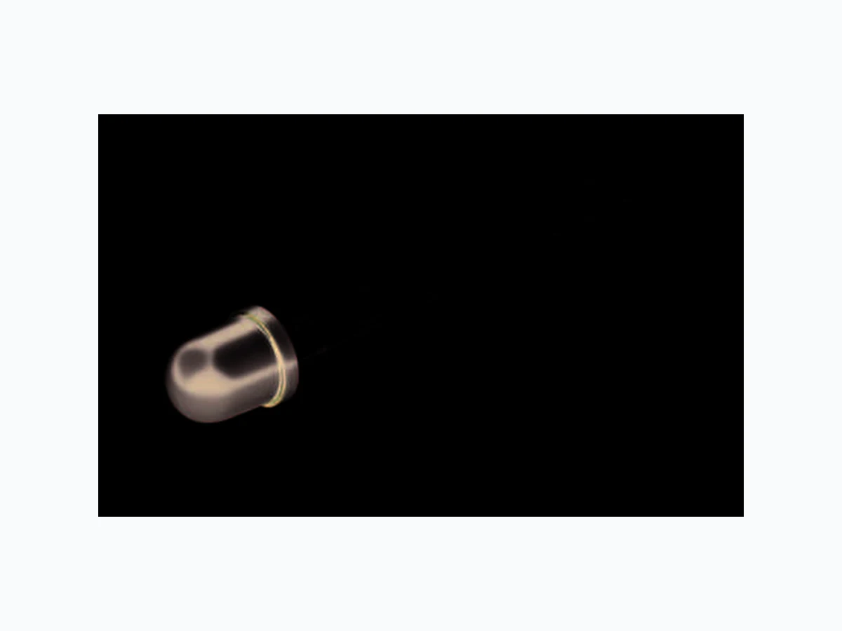
SFH314FA OSRAM
Document overview
- Manufacturer or author: Provided By www.digicamel.com(FREE DATASHEET DOWNLOAD SITE)
- PDF pages: 10
Technical content
Silicon NPN Phototransistor Version 1.3 SFH 314 FA
Ordering Information
Features: Spectral range of sensitivity: (typ) 740 ... 1080 nm
- Package: 5mm Radial (T 1 ¾), Epoxy
- Special: High linearity
Applications
Computer-controlled flashes
- Photointerrupters
- Industrial electronics
- For control and drive circuits Type: Photocurrent Ordering Code IPCE [µA] λ = 950 nm, E e = 0.5 mW/cm 2, VCE = 5 V SFH 314 FA ≥ 630 Q62702P1675 SFH 314 FA-2/3 1000 ... 3200 Q62702P3599 Note: Only one bin within one packing unit (variati on less than 2:1)
Version 1.3 SFH 314 FA Maximum Ratings (TA = 25 °C) Characteristics (TA = 25 °C) Parameter Symbol Values Unit Operating and storage temperature range T op ; T stg -40 ... 100 °C Collector-emitter voltage V CE 70 V Collector current IC 50 mA Collector surge current (τ < 10 µs) ICS 100 mA Emitter-collector voltage V EC 7 V Total Power dissipation P tot 200 mW Thermal resistance R thJA 375 K / W ESD withstand voltage (acc. to ANSI/ ESDA/ JEDEC JS-001 - HBM) VESD 2000 V Parameter Symbol Values Unit Wavelength of max. sensitivity (typ) λ S max 870 nm Spectral range of sensitivity (typ) λ 10% (typ) 740 ... 1080 nm Radiant sensitive area (typ) A 0.55 mm 2 Dimensions of chip area (typ) L x W (typ) 1 x 1 mm x mm Half angle (typ) ϕ ± 40 ° Capacitance (VCE = 5 V, f = 1 MHz, E = 0) (typ) C CE 10 pF Dark current (VCE = 10 V, E = 0) (typ (max)) I CE0 3 (≤ 200) nA Rise and fall time (IC = 1 mA, V CC = 5 V, R L = 1 kΩ) (typ) t r, t f 11 µs
Version 1.3 SFH 314 FA 2016-01-04 3 Grouping (TA = 25 °C, λ = 950 nm) Group Min Photocurrent Max Photocurrent Rise and fall time Collector-emitter saturation voltage Ee = 0.5 mW/cm 2, VCE = 5 V Ee = 0.5 mW/cm 2, VCE = 5 V IC = 1 mA, V CC = 5 V, R L = 1 kΩ IC = I PCEmin x 0.3, E e = 0.5 mW/cm 2 IPCE, min [µA] IPCE, max [µA] tr, t f [µs] VCEsat [mV] -1 630 1250 8 150 -2 1000 2000 10 150 -3 1600 3200 12 150 -4 2500 14 150 Note.: I PCEmin is the min. photocurrent of the specified group. Relative Spectral Sensitivity 1) page 9 Srel = f(λ) Photocurrent 1) page 9 IPCE = f(E e), VCE = 5 V λ OHF02331 relS 400 600 800 1000 1200 100 nm E OHF02339 e PCEΙ 10 0 -210 10 -1 110 mA -3 -210 010mW/cm 210 -3
Version 1.3 SFH 314 FA Photocurrent 1) page 9 IPCE = f(V CE ), E e = Parameter Photocurrent 1) page 9 IPCE / I PCE (25°C) = f(T A), V CE = 5 V Dark Current 1) page 9 ICEO = f(V CE ), E = 0 Dark Current 1) page 9 ICEO = f(T A), E = 0 V OHF02338 CE PCEΙ 10 0 -110 10 20 30 40 50 V 70 10 1 mA 0.5 mW cm 2 2cm mW1 2cm mW0.25 0.1 mW cm T OHF01524 A -25 0.2 0.4 0.6 0.8 1.0 1.2 1.4 1.6 0 25 50 75 100 ΙPCE PCEΙ 25 C V OHF02341 CE CEOΙ -210 10 -1 10 0 10 1 10 2 nA 10 20 30 40 50 70 V T OHF02342 A CEOΙ -110 10 0 10 1 10 2 10 3 nA 20 40 60 80 100 ˚C
Version 1.3 SFH 314 FA 2016-01-04 5 Collector-Emitter Capacitance 1) page 9 CCE = f(V CE ), f = 1 MHz, E = 0 Power Consumption Ptot = f(T A) Directional Characteristics 1) page 9 Srel = f(ϕ) V OHF02344 CE CEC 10 -2 -110 010 110 10 2V pF T OHF02340 A totP 0 20 40 60 80 ˚C 100 100 150 200 250 mW OHF02329 0 20 40 60 80 100 1200.40.60.81.0 100 010203040 0.2 0.4 0.6 0.8 1.0ϕ
Version 1.3 SFH 314 FA Package Outline Dimensions in mm (inch). Package 5mm Radial (T 1 ¾), Epoxy Approximate Weight: 0.3 g Note Packing information is available on the internet (o nline product catalog). 5.9 (0.232) 5.5 (0.217) 0.6 (0.024) 0.4 (0.016) ø5.1 (0.201) ø4.8 (0.189) 2.54 (0.100) spacing 5.7 (0.224) 5.5 (0.217) 6.9 (0.272) 6.1 (0.240) 4.0 (0.157) 3.4 (0.134) 29.5 (1.161) 27.5 (1.083) 1.8 (0.071) 1.2 (0.047) 0.8 (0.031) 0.4 (0.016) Area not flat 0.6 (0.024) 0.4 (0.016) Cathode (Diode) Chip position GEXY6630 Collector (Transistor)
Version 1.3 SFH 314 FA 2016-01-04 7 Recommended Solder Pad Dimensions in mm. Note: pad 1: emitter TTW Soldering IEC-61760-1 TTW 00 s OHA04645 100 150 200 250 300 t T 235 ˚C - 260 ˚C First wave 20 40 60 80 100 120 140 160 180 200 220 240 Second wave 10 s max., max. contact time 5 s per wave Preheating 100 ˚C 120 ˚C 130 ˚C Typical Cooling ca. 3.5 K/s typical ca. 2 K/s ca. 5 K/s Continuous line: typical process Dotted line: process limits < 150 K
Version 1.3 SFH 314 FA Disclaimer Language english will prevail in case of any discre pancies or deviations between the two language word ings. Attention please! The information describes the type of component and shall not be considered as assured characteristics . Terms of delivery and rights to change design reser ved. Due to technical requirements components may c ontain dangerous substances. For information on the types in question please con tact our Sales Organization. If printed or downloaded, please find the latest ve rsion in the Internet. Packing Please use the recycling operators known to you. We can also help you – get in touch with your nearest sales office. By agreement we will take packing material back, if it is sorted. You must bear the costs of transport . For packing material that is returned to us unsorted or which w e are not obliged to accept, we shall have to invoi ce you for any costs incurred. Components used in life-support devices or systems must be expressly authorized for such purpose! Critical components* may only be used in life-suppo rt devices** or systems with the express written ap proval of OSRAM OS. *) A critical component is a component used in a li fe-support device or system whose failure can reaso nably be expected to cause the failure of that life-support device or system, or to affect its safety or the ef fectiveness of that device or system. **) Life support devices or systems are intended (a ) to be implanted in the human body, or (b) to supp ort and/or maintain and sustain human life. If they fail, it i s reasonable to assume that the health and the life of the user may be endangered.
Version 1.3 SFH 314 FA 2016-01-04 9 Glossary 1) Typical Values: Due to the special conditions of the manufacturing processes of LED, the typical data or calculated correlations of technical parameters can only reflect statistical figures. These do not nec essarily correspond to the actual parameters of each single product, which could differ from the typical data and calculated correlations or the typical characteristic line. If requested, e.g. because of technical improvements, these typ. data will be changed without any further notice.
Version 1.3 SFH 314 FA Published by OSRAM Opto Semiconductors GmbH Leibnizstraße 4, D-93055 Regensburg www.osram-os.com © All Rights Reserved.