
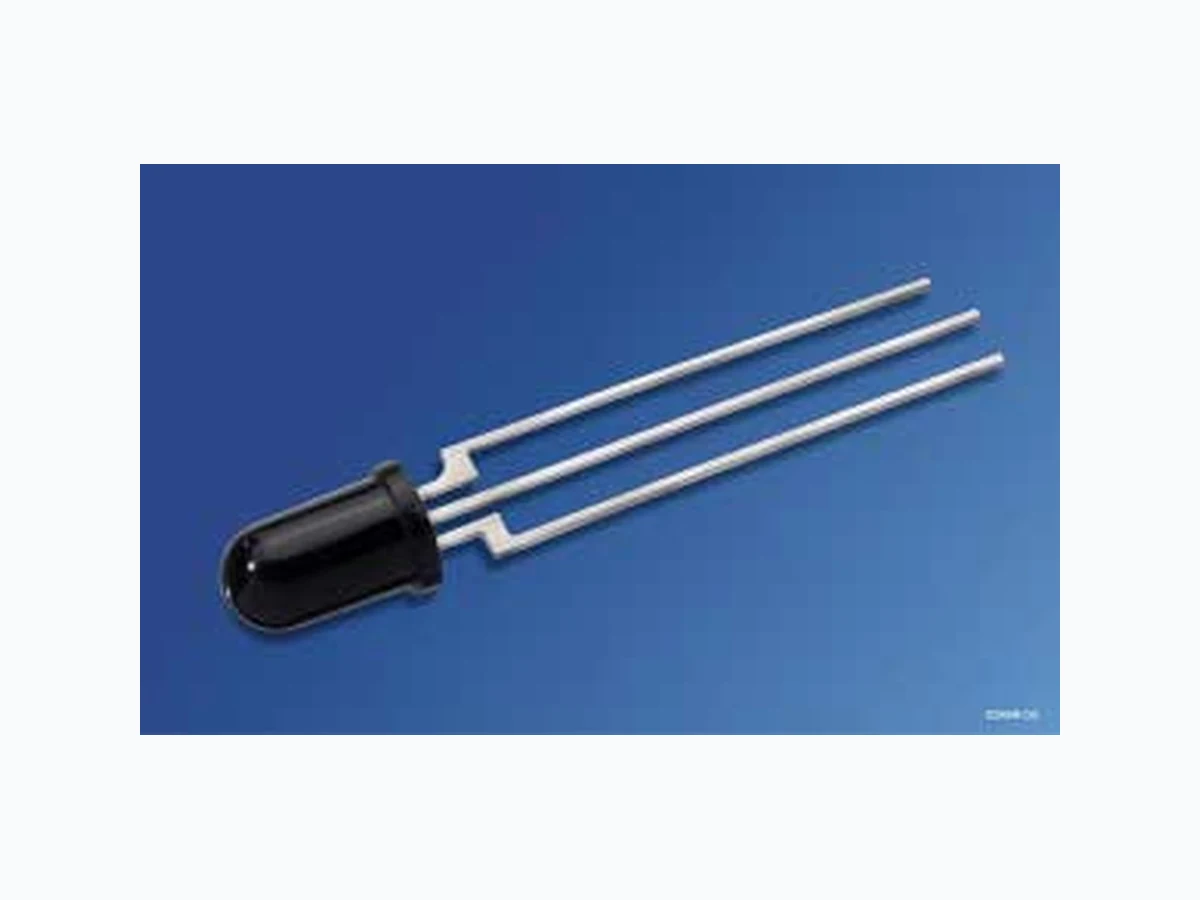
SFH303 OSRAM
Document overview
- Manufacturer or author: Provided By www.digicamel.com(FREE DATASHEET DOWNLOAD SITE)
- PDF pages: 7
Technical content
Features
Especially suitable for applications from 450 nm to 1100 nm (SFH 303) and from 730 nm to 1100 nm (SFH 303 FA) High linearity 5 mm LED plastic package with base connection Also available on tape and reel and in groups
Applications
Light-reflecting switches for steady and varying intensity Industrial electronics For control and drive circuits
SFH 303, SFH 303 FA Grenzwerte Maximum Ratings Bezeichnung Parameter Symbol Symbol Wert Value Einheit Unit Betriebs- und Lagertemperatur Operating and storage temperature range Top; Tstg – 40 … + 100 °C Kollektor-Emitterspannung Collector-emitter voltage VCE VCE (t < 2 min) V Kollektorstrom Collector current IC 50 mA Kollektorspitzenstrom, τ < 10 μs Collector surge current ICS 100 mA Emitter-Basisspannung Emitter-base voltage VEB 7 V Verlustleistung, TA = 25 °C Total power dissipation Ptot 200 mW Wärmewiderstand Thermal resistance RthJA 375 K/W
SFH 303, SFH 303 FA 2007-04-02 3 Kennwerte (TA = 25 °C, λ = 950 nm) Characteristics Bezeichnung Parameter Symbol Symbol Wert Value Einheit Unit SFH 303 SFH 303 FA Wellenlänge der max. Fotoempfindlichkeit Wavelength of max. sensitivity λS max 850 870 nm Spektraler Bereich der Fotoempfindlichkeit S = 10% von Smax Spectral range of sensitivity S = 10% of Smax λ 440 … 1100 730 … 1100 nm Bestrahlungsempfindliche Fläche Radiant sensitive area A 0.20 0.20 mm2 Abmessung der Chipfläche Dimensions of chip area L × B L × W 0.65 × 0.65 0.65 × 0.65 mm × mm Halbwinkel Half angle ϕ ± 20 ± 20 Grad deg. Fotostrom der Kollektor-Basis-Fotodiode Photocurrent of collector-base photodiode Ee = 0.5 mW/cm2, VCB = 5 V Ev = 1000 Ix, Normlicht/standard light A, VCB = 5 V IPCB IPCB 15.8 4.5 μA μA Kapazität Capacitance VCE = 0 V, f = 1 MHz, E = 0 VCB = 0 V, f = 1 MHz, E = 0 VEB = 0 V, f = 1 MHz, E = 0 CCE CCB CEB pF pF pF Dunkelstrom Dark current VCEO = 10 V, E = 0 ICEO 5 (≤ 50) 5 (≤ 50) nA
SFH 303, SFH 303 FA Die Fototransistoren werden nach ihrer Fotoempfindlichkeit gruppiert und mit arabischen Ziffern gekennzeichnet. The phototransistors are grouped according to their spectral sensitivity and distinguished by arabian figures. Bezeichnung Parameter Symbol Symbol Wert Value Einheit Unit -2 -3 -4 Fotostrom, λ = 950 nm Photocurrent Ee = 0.5 mW/cm2, VCE = 5 V SFH 303: Ev = 1000 Ix, Normlicht/standard light A, VCE = 5 V IPCE IPCE 1.0 … 2.0 5.2 1.6 … 3.2 8.4 ≥ 2.5 13.1 mA mA Anstiegszeit/Abfallzeit Rise and fall time IC = 1 mA, VCC = 5 V, RL = 1 kΩ tr, tf 11 13 15 μs Kollektor-Emitter-Sättigungsspannung Collector-emitter saturation voltage IC = IPCEmin 1) × 0.3, Ee = 0.5 mW/cm2 VCEsat 150 150 150 mV Stromverstärkung Current gain Ee = 0.5 mW/cm2, VCE = 5 V 330 530 830 – 1) IPCEmin ist der minimale Fotostrom der jeweiligen Gruppe. 1) IPCEmin is the min. photocurrent of the specified group. IPCE IPCB
SFH 303, SFH 303 FA 2007-04-02 5 Relative Spectral Sensitivity, SFH 303 Srel = f (λ) Output Characteristics IC = f (VCE), IB = Parameter Directional Characteristics Srel = f (ϕ) Relative Spectral Sensitivity, SFH 303 FA Srel = f (λ) Dark Current ICEO = f (VCE), E = 0 Photocurrent IPCE = f (Ee), VCE = 5 V Capacitance C = f (VR), f = 1 MHz, E = 0 V OHF00291 r -310 C V pF C EB CBC CEC 10 -2 10 -1 10 0 10 1 10 2
SFH 303, SFH 303 FA Maßzeichnung Package Outlines Maße in mm (inch) / Dimensions in mm (inch). Lötbedingungen Soldering Conditions Wellenlöten (TTW) (nach CECC 00802) TTW Soldering (acc. to CECC 00802) 9.0 (0.354) 8.2 (0.323) 25.2 (0.992) 24.2 (0.953) 1.8 (0.071) 1.2 (0.047) 7.8 (0.307) 7.5 (0.295) 0.7 (0.028) 0.4 (0.016) 0.6 (0.024) 10.9 (0.429) 6.9 (0.272) 2.54 (0.100) spacing 2.54 (0.100) spacing 5.1 (0.201) 4.8 (0.189) 5.9 (0.232) 5.5 (0.217) 0.6 (0.024) 0.4 (0.016) B Chip position Area not flat GEOY6351 CE OHLY0598 50 100 150 200 250 100 150 200 250 300 T t C s 235 C 10 s C... 260 1. Welle 1. wave 2. Welle 2. wave
5 K/s 2 K/sca 200 K/s
CC... 130100
2 K/s
Zwangskühlung forced cooling Normalkurve standard curve Grenzkurven limit curves
SFH 303, SFH 303 FA 2007-04-02 7 Published by OSRAM Opto Semiconductors GmbH Wernerwerkstrasse 2, D-93049 Regensburg www.osram-os.com © All Rights Reserved. Attention please! The information describes the type of component and shall not be considered as assured characteristics. Terms of delivery and rights to change design reserv ed. Due to technical requirements components may contain dangerous substances. For information on the types in question please contact our Sales Organization. Packing Please use the recycling operators known to you. We can also help you – get in touch with your nearest sales office. By agreement we will take packing material back, if it is sorted. You must bear the costs of tr ansport. For packing material that is returned to us unsorted or which we are not obliged to accept, we shall have to invoice you for any costs incurred. Components used in life-support devices or system s must be expressly authorized for such purpose! Critical components 1 , may only be used in life-support devices or systems 2 with the express written approval of OSRAM OS. 1 A critical component is a component usedin a life-support device or system whose failure can reasonably be expected to cause the failure of that life-support device or system, or to affect its safety or effectiveness of that device or system. 2 Life support devices or systems are intended (a) to be implanted in the human body, or (b) to support and/or maintain and sustain human life. If they fail, it is reasonable to assume that the health of the user may be endangered.