
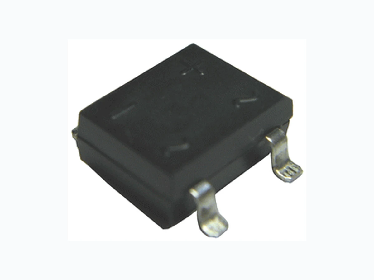
SDB103 ETC2
Document overview
- Manufacturer or author: Provided By www.digicamel.com(FREE DATASHEET DOWNLOAD SITE)
- PDF pages: 3
Technical content
Features
y Glass passivated die construction y Ideal for automatic insertion y Plastic material used carries UL flammability recognition 94V-0 y High surge current capability Circuit Mechanical Data Case: Molded plastic case Terminals: Plated leads solderable per MIL-STD-750, Method 2026 Polarity: Marked on Body Mounting Position: Any Module Type TYPE VRRM VRSM SDB103 SDB104 SDB105 SDB106 SDB107 200V 400V 600V 800V 1000V 300V 500V 700V 900V 1100V Maximum Ratings and Thermal Characteristics (TA = 25℃ unless otherwise noted) Symbol Conditions Values Units IF(AV) Maximum average forward output rectified current Tc =40 ℃ 1.0 A IFSM Peak forward surge current single half sine-wave superimposed on rated load (JEDEC Method) 30 A i2t Rating for fusing (t<8.3ms) 3.7 A2s RθJA RθJC Maximum thermal resistance per leg 40 15 ℃/W Tj, TSTG Operating Junction and storage temperature range -55 to +150 ℃ Weight Approximate Weight 0.4 g Electrical Characteristics (TA = 25℃ unless otherwise noted) Symbol Conditions Values Units VF Maximum Instantaneous Forward Voltage per leg I FM =1.0A 1.1 V IR Maximum DC reverse current at rated T A = 25℃ DC blocking voltage per leg T A = 125℃ 5.0 500 µA CJ Typical Junction Capacitance per leg V R=4.0V 1.0MHZ 25 PF Notes: (1) Thermal resistance from junction to am bient and from junction to lead mounted on P.C.B. with 0.47x0.47” (12 x12mm) copper pads.
D o c u m e n t N u m b e r : S D B 1 0 3 t h r u S D B 1 0 7 www. N o v . 1 3 , 2 0 0 9 2 smsemi.com Performance Curves IF, INSTANTANEOUS FORWARD CURRENT (A) 1.0 0.1 0.01 2.0 1.5 1.0 0.5 Tj=25ºC Pulse Width=300μs 2% duty cycle 60Hz Resistive or Inductive load IO, AVERAGE FORWARD CURRENT (A) 0 50 100 150 TA, AMBIENT TEMPERATURE (ºC) Fig.1 Output Current Derating Curve VF, INSTANTANEOUS FORWARD VOLTAGE (V) Fig.2 Typ Forward Characteristics (per element) 1 10 100 NUMBER OF CYCLES AT 60Hz Fig.3 Max Non-Repetitive Peak Forward Surge Current Cj, CAPACITANCE (pF) 100 Single Half Sine-Wave (JEDEC Method) IFSM, PEAK FORWARD SURGE CURRENT (A) Tj=25ºC f =1MHZ Vsig=50mV p-p 1 10 100 VR, REVERSE VOLTAGE (V) Fig.4 Typ Junction Capacitance (per element) Tj=125ºC Tj=25ºC 0 20 40 60 80 100 120 140 PERCENT OF RATED PEAK REVERSE VOLTAGE (%) Fig.5 Typical Reverse Characteristics per element IR, INSTANTANEOUS REVERSE CURRENT (μA) 100 1.0 0.1 0.01
D o c u m e n t N u m b e r : S D B 1 0 3 t h r u S D B 1 0 7 www. N o v . 1 3 , 2 0 0 9 3 smsemi.com Package Outline Information 0.047(1.20) 0.040(1.02) 0.205(5.2) 0.195(5.0) 0.346(8.80) 0.316(8.05) 0.134(3.40) 0.102(2.60) 0.410(10.4) 0.370(9.40) 0.335(8.5) 0.245(6.2) 0.060(1.524) 0.040(1.016) 0.013(0.330) 0.003(0.076) 0.014(0.350) 0.008(0.203) CASE: SDB-1 Dimensions in inches (mm)