
SCR LITTELFUSE
Document overview
- Manufacturer or author: Provided By www.digicamel.com(free datasheet download site)
- PDF pages: 2
Technical content
© 2016 Littelfuse Protection Relays & Controls Flashers and Tower Lighting Controls Tower and Obstruction Lighting Controls www.littelfuse.com/scr Rev: 1-A-062316 Wiring Diagram SCR SERIES Universal Lamp Alarm Relay
Description
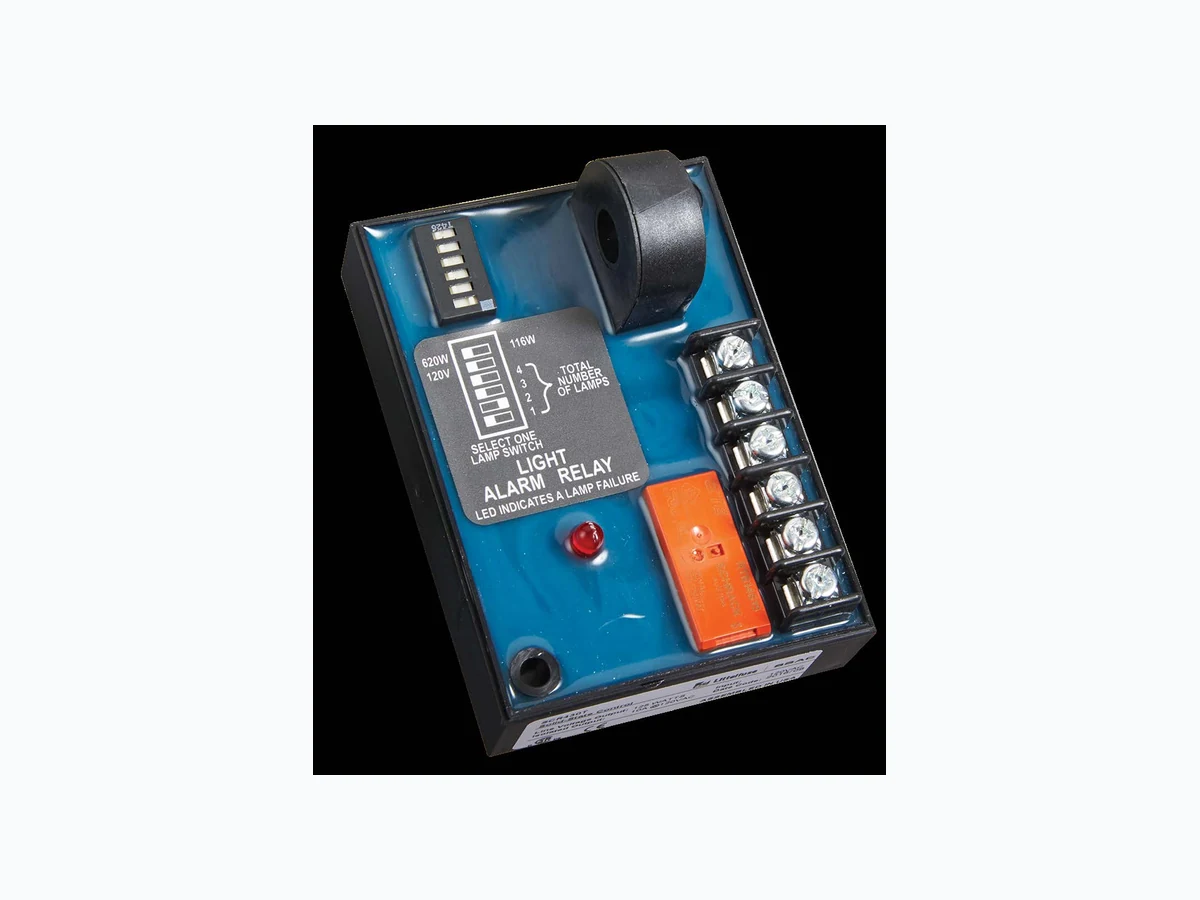
The SCR series is a universal lamp alarm relay designed to sense the failure of flashing or steady incandescent beacon lamps or steady side lights. The toroidal current sensor provides isolation and allows monitoring of more than one line at a time. The SCR Series energizes when one or more lamps fail. It will monitor the operation of one to four side lights and up to four beacon lamps. Operation When a lamp fails, the SCR Series senses a decrease in current flow. After a fixed time delay, the LED glows and the two alarm outputs energize. The outputs and the LED are reset when the failed lamps are replaced and the current returns to the nominal setting, or when the input voltage is removed. The SCR will sense an open flasher, it will not sense a continuously ON flasher (see FB Series). Features & Benefits FEATURES BENEFITS T oroidal current sensing Provides isolation from the lighting circuit and allows monitoring of multiple lines simultaneously Monitors 1-4 side lights or up to 4 beacon lamps Senses failed incandescent flashing beacon or steady obstruction lamps Isolated, 10A, SPDT alarm output plus one 1A, solid-state line voltage alarm output Provides alarm indication and can also be used for remote monitoring of the lighting system Fixed trip delay (6s) Prevents nuisance alarms Switch selectable number, voltage, and wattage of lamps User selectable to meet wide application needs with one relay (SCR430T only) L1 N/L2 L1 N/L2 BEACON LAMP CONNECTION DIAGRAM OBSTRUCTION LAMP CONNECTION DIAGRAM V = Voltage B = Beacon Lamps SS = Selector Switch T = Toroid F = Flasher AXL = Auxiliary Load/Alarm Relay contacts are isolated. V = Voltage SS = Selector Switch T = Toroid AXL = Auxiliary Load/Alarm OL = Obstruction Lamps Relay contacts are isolated.
Ordering Information
SCR430T 120VAC Incandescent SCR630T 230VAC Incandescent If you don’t find the part you need, call us for a custom product 800-843-8848
© 2016 Littelfuse Protection Relays & Controls Flashers and Tower Lighting Controls Tower and Obstruction Lighting Controls www.littelfuse.com/scr Rev: 1-A-062316 SCR SERIES Selection Range SCR430T SCR630T 700 Wa. 620 W b. 120 V c. c. a.116 W 130 V 116 W a. Lamp Wattage - Select the lamp wattage of the lamps in use. b. Lamp Voltage - Select the lamp voltage shown on the lamp (SCR430T) c. Lamps ON - Select the number of lamps on during normal operation. Only one lamp switch at a time may be transferred to the right. Programming Example SCR430T SCR630T 700 Wa. 620 W b. 120 V c. c. a.116 W 130 V 116 W Example Shown: SCR430T -620 watts at 120 VAC lamps, two lamps are ON during normal operation. STEP 1. Select lamp wattage: 1 16 or 620 watts 2. Select the number of lamps ON (1 thru 4) during normal operation. Only one lamp switch may be ON (RIGHT) at any time. Specifications Operation Lamp Monitoring Capacity (in lamps) 100W 116W 620W 700W SCR430T 120VAC Lamps 4 4 4 n/a SCR630T 230VAC Lamps n/a 4 n/a 4 Time Delay Trip Delay Factory fixed ≅ 6s Input Input Voltage/Tolerance SCR430T - 120VAC ±10% SCR630T - 230VAC ±10% AC Line Frequency 50/60Hz Output To operate a spare lamp or alarm Line Voltage Output (Solid-state Rated) ≤ 125W @ 120VAC ≤ 250W @ 240VAC Isolated Alarm Output (SPDT) 10A @ 240VAC or 30VDC resistive; 1/4 hp @ 125VAC; 1/2 hp @ 250VAC Mechanical Mounting Two #6 (M3.5 x 0.6) screws Dimensions H 88.9 mm (3.5”); W 63.5 mm (2.5”); D 44.5 mm (1.75”) Termination Screws with captive clamps for up to 14 AWG (2.45 mm 2) wire Protection Circuitry Encapsulated Environmental Operating Temperature -55° to 65°C Weight ≅ 6.8 oz (193 g)