
 Download PDF
SCM AVX
Document overview
- PDF pages: 12
Technical content
Page 1
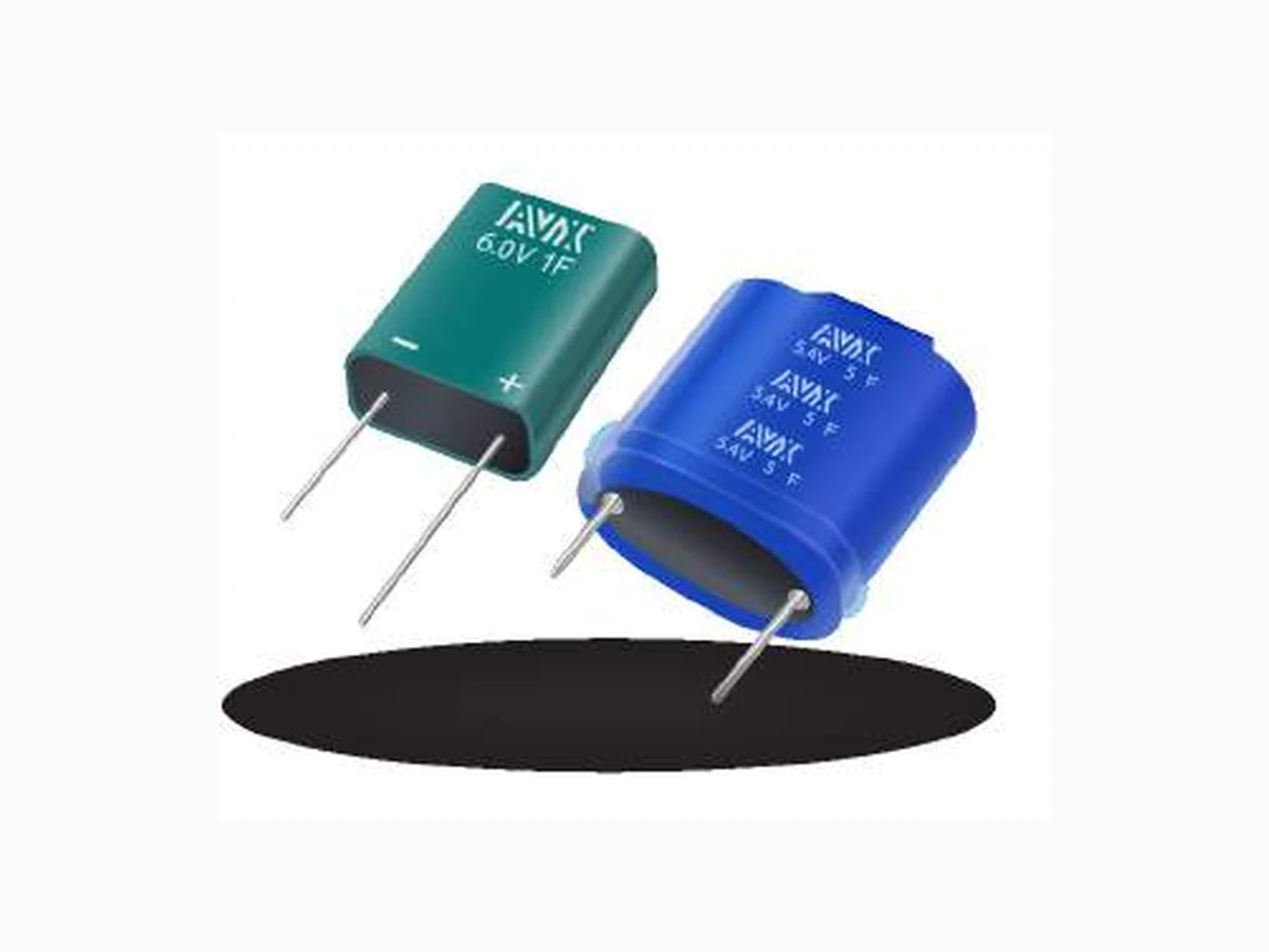
This new series of electrochemical, double-layer, series-connected SuperCapacitor modules offers excellent pulse power handling characteristics based on the combination of very high capacitance and very low ESR. Used by themselves or in conjunction with primary or secondary batteries, they provide extended back up time, longer battery life, and provide instantaneous power pulses as needed. Offers great solutions to hold up, energy harvesting, pulse power applications, and battery replacement.
APPLICATIONS
FEATURES
- High Pulse Power Capability
- Camera Flash Systems
- Low ESR
- Energy Harvesting
- Low Leakage Current
- GSM/GPRS Pulse Applications
- Plastic, Moisture Resistant Version
HOW TO ORDER
14 C
SCM R
474
P
Case
Series Diameter
Voltage Capacitance Code Tolerance 1st two digits
SuperCap Q = 6.3mm
Code
P = +100%/-0%
Length
S = +30%/-10% represent
Module R = 8mm / 9.5mm\*\*
C = 5.0V Two digits
significant figures
S = 10mm
D = 5.4V represent
3rd digit represents
T = 12.5mm
case F = 5.5V
U = 16mm
multiplier (number
length G = 7.5V in mm
of zeros to follow) H = 6.0V J = 8.1V L = 9.0V
QUALITY INSPECTION
Parts are tested for life cycle, high temperature load life, temperature characteristics, vibration resistance, and humidity characteristics. See pages 2-5 for more information.
- UPS/Industrial
- Wireless Alarms
- Remote Metering
- Scanners
- Toys and Games
0
R
B A
Lead Orientation
Package/Lead Format Package Balancing
0 = Straight Leads
R = Shrink Wrap/Radial B = Bulk A = Unbalanced S = Plastic/Radial
1 = Bent Leads\*
T = Tray\* B = Passive Balanced
\*Inquire about availability \*\*Plastic/Radial version
TERMINATION
These SuperCapacitors are compatible with hand soldering, as well as reflow and wave soldering processes, so long as appropriate precautions are followed. See page 11 for more information.
LEAD-FREE COMPATIBLE
COMPONENT
For RoHS compliant products, please select correct termination style.
Page 2
5.4V/5.0V SCM Series
| AVX Part Number | Diameter (mm) | Length (mm) | Rated Capacitance (F) | Capacitance Tolerance | Rated Voltage (V) | Rated Temperature (°C) | DCL Max @ 72 Hrs (µA) | ESR Max @ 1000 Hz (mΩ) | ESR Max @ DC (mΩ) | Peak Current (A) | Power Density (W/kg) | Max Energy (Wh) | Energy Density (Wh/kg) |
|---|---|---|---|---|---|---|---|---|---|---|---|---|---|
| Shrink Wrap / Radial Lead | |||||||||||||
| SCMQ14C474PRBA0 | 6.3 | 14 | 0.47 | +100%/-0% | 5.0/4.2* | 65/85* | 2 | 400 | 1000 | 0.80 | 2143 | 0.0016 | 1.17 |
| SCMQ14C474PRTA0 | 6.3 | 14 | 0.47 | +100%/-0% | 5.0/4.2* | 65/85* | 2 | 400 | 1000 | 0.80 | 2143 | 0.0016 | 1.17 |
| SCMQ14D474PRBB0 | 6.3 | 14 | 0.47 | +100%/-0% | 5.4/4.6* | 65/85* | 6 | 400 | 1000 | 0.86 | 2499 | 0.0019 | 1.36 |
| SCMQ14D474PRTB0 | 6.3 | 14 | 0.47 | +100%/-0% | 5.4/4.6* | 65/85* | 6 | 400 | 1000 | 0.86 | 2499 | 0.0019 | 1.36 |
| SCMR14C474PRBA0 | 8 | 14 | 0.47 | +100%/-0% | 5.0/4.2* | 65/85* | 2 | 300 | 1000 | 0.80 | 1429 | 0.0016 | 0.78 |
| SCMR14D474PRBB0 | 8 | 14 | 0.47 | +100%/-0% | 5.4/4.6* | 65/85* | 6 | 300 | 1000 | 0.86 | 1666 | 0.0019 | 0.91 |
| SCMR18C105PRBA0 | 8 | 18 | 1 | +100%/-0% | 5.0/4.2* | 65/85* | 6 | 200 | 720 | 1.45 | 1667 | 0.0035 | 1.39 |
| SCMR18D105PRBB0 | 8 | 18 | 1 | +100%/-0% | 5.4/4.6* | 65/85* | 10 | 200 | 720 | 1.57 | 1944 | 0.0041 | 1.62 |
| SCMR22C155PRBA0 | 8 | 22 | 1.5 | +100%/-0% | 5.0/4.2* | 65/85* | 10 | 190 | 580 | 2.01 | 1669 | 0.0052 | 1.68 |
| SCMR22D155PRBB0 | 8 | 22 | 1.5 | +100%/-0% | 5.4/4.6* | 65/85* | 15 | 190 | 580 | 2.17 | 1946 | 0.0061 | 1.96 |
| SCMS22C255PRBA0 | 10 | 22 | 2.5 | +100%/-0% | 5.0/4.2* | 65/85* | 20 | 140 | 360 | 3.29 | 1852 | 0.0087 | 1.93 |
| SCMS22D255PRBB0 | 10 | 22 | 2.5 | +100%/-0% | 5.4/4.6* | 65/85* | 25 | 140 | 360 | 3.55 | 2113 | 0.0101 | 2.20 |
| SCMT22C505PRBA0 | 12.5 | 22 | 5 | +100%/-0% | 5.0/4.2* | 65/85* | 25 | 100 | 150 | 7.14 | 2740 | 0.0174 | 2.38 |
| SCMT22D505PRBB0 | 12.5 | 22 | 5 | +100%/-0% | 5.4/4.6* | 65/85* | 30 | 100 | 150 | 7.71 | 3069 | 0.0203 | 2.66 |
| SCMT32C755SRBA0 | 12.5 | 32 | 7.5 | +30%/-10% | 5.0/4.2* | 65/85* | 65 | 70 | 160 | 8.52 | 1953 | 0.0260 | 2.71 |
| SCMT32D755SRBB0 | 12.5 | 32 | 7.5 | +30%/-10% | 5.4/4.6* | 65/85* | 70 | 70 | 160 | 9.20 | 2209 | 0.0304 | 3.07 |
\*with appropriate voltage derating operating temperature can be extended to 85°C
OPERATING TEMPERATURE RANGE
-40°C to +65°C @ 5.4V Balanced, 5.0V Unbalanced -40°C to +85°C @ 4.6V Balanced, 4.2V Unbalanced
QUALIFICATION TEST SUMMARY
| Test | Test Method | Parameter | Limits |
|---|---|---|---|
| Life Cycle | Capacitors are cycled between rated voltage and half-rated voltage under constant current at +25°C for 500,000 cycles | Capacitance Change ESR Appearance | ≤30% of initial value ≤2 times initial value No remarkable defects |
| High Temperature Load Life | Temperature: +65°C Voltage: Rated Voltage Test Duration: 2,000 hours | Capacitance Change ESR Appearance | ≤30% of initial value ≤2 times initial value No remarkable defects |
| Storage Temperature Characteristics | Storage Duration: 1 year No Load Temperature: +25°C | Capacitance Change ESR Appearance | ≤30% of initial value ≤2 times initial value No remarkable defects |
| Vibration Resistance | Amplitude: 1.5mm Frequency: 10 ~ 55Hz Direction: X, Y, Z for 2 hours each | Capacitance Change ESR Appearance | ≤30% of initial value ≤2 times initial value No remarkable defects |
| Humidity | Voltage: Rated Voltage RH: 90% Temperature: +60°C Test Duration: 1,500 hours | Capacitance Change ESR Appearance | ≤30% of initial value ≤2 times initial value No remarkable defects |
Page 3
6.0V/5.5V SCM Series
| AVX Part Number | Diameter (mm) | Length (mm) | Rated Capacitance (F) | Capacitance Tolerance | Rated Voltage (V) | Rated Temperature (°C) | DCL Max @ 72 Hrs (µA) | ESR Max @ 1000 Hz (mΩ) | ESR Max @ DC (mΩ) | Peak Current (A) | Power Density (W/kg) | Max Energy (Wh) | Energy Density (Wh/kg) |
|---|---|---|---|---|---|---|---|---|---|---|---|---|---|
| Shrink Wrap / Radial Lead | |||||||||||||
| SCMQ14F474PRBA0 | 6.3 | 14 | 0.47 | +100%/-0% | 5.5 | 65 | 6 | 500 | 3000 | 0.54 | 864 | 0.0020 | 1.41 |
| SCMQ14H474PRBB0 | 6.3 | 14 | 0.47 | +100%/-0% | 6.0 | 65 | 7 | 500 | 3000 | 0.59 | 1029 | 0.0024 | 1.68 |
| SCMR14F474PRBA0 | 8 | 14 | 0.47 | +100%/-0% | 5.5 | 65 | 6 | 380 | 1720 | 0.71 | 1005 | 0.0020 | 0.94 |
| SCMR14H474PRBB0 | 8 | 14 | 0.47 | +100%/-0% | 6.0 | 65 | 7 | 380 | 1720 | 0.78 | 1196 | 0.0024 | 1.12 |
| SCMR18F105PRBA0 | 8 | 18 | 1 | +100%/-0% | 5.5 | 65 | 6 | 250 | 720 | 1.60 | 2017 | 0.0042 | 1.68 |
| SCMR18H105PRBB0 | 8 | 18 | 1 | +100%/-0% | 6.0 | 65 | 12 | 250 | 720 | 1.74 | 2400 | 0.0050 | 2.00 |
| SCMR22F155PRBA0 | 8 | 22 | 1.5 | +100%/-0% | 5.5 | 65 | 12 | 200 | 560 | 2.24 | 2091 | 0.0063 | 2.03 |
| SCMR22H155PRBB0 | 8 | 22 | 1.5 | +100%/-0% | 6.0 | 65 | 18 | 200 | 560 | 2.45 | 2488 | 0.0075 | 2.42 |
| SCMS22F255PRBA0 | 10 | 22 | 2.5 | +100%/-0% | 5.5 | 65 | 24 | 180 | 340 | 3.72 | 2373 | 0.0105 | 2.33 |
| SCMS22H255PRBB0 | 10 | 22 | 2.5 | +100%/-0% | 6.0 | 65 | 30 | 180 | 340 | 4.05 | 2762 | 0.0125 | 2.72 |
| SCMS32F505PRBA0 | 10 | 32 | 5 | +100%/-0% | 5.5 | 65 | 30 | 120 | 150 | 7.86 | 3580 | 0.0210 | 3.11 |
| SCMS32H505PRBB0 | 10 | 32 | 5 | +100%/-0% | 6.0 | 65 | 36 | 120 | 150 | 8.57 | 4235 | 0.0250 | 3.68 |
| SCMT22F505PRBA0 | 12.5 | 22 | 5 | +100%/-0% | 5.5 | 65 | 30 | 120 | 150 | 7.86 | 3176 | 0.0210 | 2.76 |
| SCMT32F755SRBA0 | 12.5 | 32 | 7.5 | +30%/-10% | 5.5 | 65 | 78 | 90 | 120 | 10.86 | 3151 | 0.0315 | 3.28 |
| SCMT32H755SRBB0 | 12.5 | 32 | 7.5 | +30%/-10% | 6.0 | 65 | 84 | 90 | 120 | 11.84 | 3600 | 0.0375 | 3.75 |
| SCMU33F156SRBB0 | 16 | 33 | 15 | +30%/-10% | 5.5 | 65 | 70 | 35 | 50 | 23.57 | 3946 | 0.0630 | 3.43 |
| Plastic / Radial Lead | |||||||||||||
| SCMR14F474PSBA0 | 9.5 | 16 | 0.47 | +100%/-0% | 5.5 | 65 | 3 | 380 | 1720 | 0.71 | 541 | 0.0020 | 0.51 |
| SCMR14H474PSBB0 | 9.5 | 16 | 0.47 | +100%/-0% | 6.0 | 65 | 7 | 380 | 1720 | 0.78 | 644 | 0.0024 | 0.60 |
| SCMR18F105PSBA0 | 9.5 | 20 | 1 | +100%/-0% | 5.5 | 65 | 7 | 250 | 720 | 1.60 | 1096 | 0.0042 | 0.91 |
| SCMR18H105PSBB0 | 9.5 | 20 | 1 | +100%/-0% | 6.0 | 65 | 12 | 250 | 720 | 1.74 | 1304 | 0.0050 | 1.09 |
| SCMR22F155PSBA0 | 9.5 | 24 | 1.5 | +100%/-0% | 5.5 | 65 | 12 | 200 | 560 | 2.24 | 1179 | 0.0063 | 1.15 |
| SCMR22H155PSBB0 | 9.5 | 24 | 1.5 | +100%/-0% | 6.0 | 65 | 18 | 200 | 560 | 2.45 | 1403 | 0.0075 | 1.36 |
OPERATING TEMPERATURE RANGE
-40°C to +65°C
QUALIFICATION TEST SUMMARY
| Test | Test Method | Parameter | Limits |
|---|---|---|---|
| Life Cycle | Capacitors are cycled between rated voltage and half-rated voltage under constant current at +25°C for 500,000 cycles | Capacitance Change ESR Appearance | ≤30% of initial value ≤2 times initial value No remarkable defects |
| High Temperature Load Life | Temperature: +65°C Voltage: Rated Voltage Test Duration: 2,000 hours | Capacitance Change ESR Appearance | ≤30% of initial value ≤2 times initial value No remarkable defects |
| Storage Temperature Characteristics | Storage Duration: 1 year No Load Temperature: +25°C | Capacitance Change ESR Appearance | ≤30% of initial value ≤2 times initial value No remarkable defects |
| Vibration Resistance | Amplitude: 1.5mm Frequency: 10 ~ 55Hz Direction: X, Y, Z for 2 hours each | Capacitance Change ESR Appearance | ≤30% of initial value ≤2 times initial value No remarkable defects |
| Humidity | Voltage: Rated Voltage RH: 90% Temperature: +60°C Test Duration: 1,500 hours | Capacitance Change ESR Appearance | ≤30% of initial value ≤2 times initial value No remarkable defects |
Page 4
7.5V SCM Series
| AVX Part Number | Diameter (mm) | Length (mm) | Rated Capacitance (F) | Capacitance Tolerance | Rated Voltage (V) | Rated Temperature (°C) | DCL Max @ 72 Hrs (µA) | ESR Max @ 1000 Hz (mΩ) | ESR Max @ DC (mΩ) | Peak Current (A) | Power Density (W/kg) | Max Energy (Wh) | Energy Density (Wh/kg) |
|---|---|---|---|---|---|---|---|---|---|---|---|---|---|
| Shrink Wrap / Radial Lead | |||||||||||||
| SCMR14G334SRBA0 | 8 | 14 | 0.33 | +30%/-10% | 7.5/6.4* | 65/85* | 2 | 450 | 900 | 0.95 | 2419 | 0.0026 | 0.83 |
| SCMR14G334SRBB0 | 8 | 14 | 0.33 | +30%/-10% | 7.5/6.4* | 65/85* | 6 | 450 | 900 | 0.95 | 2419 | 0.0026 | 0.83 |
| SCMR18G604SRBA0 | 8 | 18 | 0.6 | +30%/-10% | 7.5/6.4* | 65/85* | 6 | 225 | 450 | 1.77 | 3947 | 0.0047 | 1.23 |
| SCMR18G604SRBB0 | 8 | 18 | 0.6 | +30%/-10% | 7.5/6.4* | 65/85* | 10 | 225 | 450 | 1.77 | 3846 | 0.0047 | 1.20 |
| SCMR22G105SRBA0 | 8 | 22 | 1 | +30%/-10% | 7.5/6.4* | 65/85* | 10 | 180 | 360 | 2.76 | 4076 | 0.0078 | 1.70 |
| SCMR22G105SRBB0 | 8 | 22 | 1 | +30%/-10% | 7.5/6.4* | 65/85* | 15 | 180 | 360 | 2.76 | 3989 | 0.0078 | 1.66 |
\*with appropriate voltage derating operating temperature can be extended to 85°C
OPERATING TEMPERATURE RANGE
-40°C to +65°C @ 7.5V -40°C to +85°C @ 6.4V
QUALIFICATION TEST SUMMARY
| Test | Test Method | Parameter | Limits |
|---|---|---|---|
| Life Cycle | Capacitors are cycled between rated voltage and half-rated voltage under constant current at +25°C for 500,000 cycles | Capacitance Change ESR Appearance | ≤30% of initial value ≤2 times initial value No remarkable defects |
| High Temperature Load Life | Temperature: +65°C Voltage: Rated Voltage Test Duration: 2,000 hours | Capacitance Change ESR Appearance | ≤30% of initial value ≤2 times initial value No remarkable defects |
| Storage Temperature Characteristics | Storage Duration: 1 year No Load Temperature: +25°C | Capacitance Change ESR Appearance | ≤30% of initial value ≤2 times initial value No remarkable defects |
| Vibration Resistance | Amplitude: 1.5mm Frequency: 10 ~ 55Hz Direction: X, Y, Z for 2 hours each | Capacitance Change ESR Appearance | ≤30% of initial value ≤2 times initial value No remarkable defects |
| Humidity | Voltage: Rated Voltage RH: 90% Temperature: +60°C Test Duration: 1,500 hours | Capacitance Change ESR Appearance | ≤30% of initial value ≤2 times initial value No remarkable defects |
Page 5
9.0V/8.1V SCM Series
| AVX Part Number | Diameter (mm) | Length (mm) | Rated Capacitance (F) | Capacitance Tolerance | Rated Voltage (V) | Rated Temperature (°C) | DCL Max @ 72 Hrs (µA) | ESR Max @ 1000 Hz (mΩ) | ESR Max @ DC (mΩ) | Peak Current (A) | Power Density (W/kg) | Max Energy (Wh) | Energy Density (Wh/kg) |
|---|---|---|---|---|---|---|---|---|---|---|---|---|---|
| Shrink Wrap / Radial Lead | |||||||||||||
| SCMR14J334SRBA0 | 8 | 14 | 0.33 | +30%/-10% | 8.1 | 65 | 3 | 500 | 2850 | 0.69 | 897 | 0.0030 | 0.98 |
| SCMR14J334SRBB0 | 8 | 14 | 0.33 | +30%/-10% | 9.0 | 65 | 6 | 500 | 2850 | 0.69 | 869 | 0.0030 | 0.95 |
| SCMR14L334SRBB0 | 8 | 14 | 0.33 | +30%/-10% | 9.0 | 65 | 7 | 500 | 2850 | 0.77 | 1072 | 0.0037 | 1.17 |
| SCMR18J604SRBA0 | 8 | 18 | 0.6 | +30%/-10% | 8.1 | 65 | 7 | 400 | 1080 | 1.47 | 1934 | 0.0055 | 1.45 |
| SCMR18J604SRBB0 | 8 | 18 | 0.6 | +30%/-10% | 9.0 | 65 | 15 | 400 | 1080 | 1.47 | 1869 | 0.0055 | 1.40 |
| SCMR18L604SRBB0 | 8 | 18 | 0.6 | +30%/-10% | 9.0 | 65 | 12 | 400 | 1080 | 1.64 | 2308 | 0.0068 | 1.73 |
| SCMR22J105SRBA0 | 8 | 22 | 1 | +30%/-10% | 8.1 | 65 | 12 | 350 | 840 | 2.20 | 1986 | 0.0091 | 1.93 |
| SCMR22J105SRBB0 | 8 | 22 | 1 | +30%/-10% | 8.1 | 65 | 15 | 350 | 840 | 2.20 | 1894 | 0.0091 | 1.84 |
| SCMR22L105SRBB0 | 8 | 22 | 1 | +30%/-10% | 9.0 | 65 | 18 | 350 | 840 | 2.45 | 2338 | 0.0113 | 2.27 |
| Plastic / Radial Lead | |||||||||||||
| SCMR14J334SSBA0 | 9.5 | 16 | 0.33 | +30%/-10% | 8.1 | 65 | 3 | 500 | 2850 | 0.69 | 498 | 0.0030 | 0.54 |
| SCMR14L334SSBB0 | 9.5 | 16 | 0.33 | +30%/-10% | 9.0 | 65 | 7 | 500 | 2850 | 0.77 | 598 | 0.0037 | 0.65 |
| SCMR18J604SSBA0 | 9.5 | 20 | 0.6 | +30%/-10% | 8.1 | 65 | 7 | 400 | 1080 | 1.47 | 1063 | 0.0055 | 0.80 |
| SCMR18L604SSBB0 | 9.5 | 20 | 0.6 | +30%/-10% | 9.0 | 65 | 12 | 400 | 1080 | 1.64 | 1286 | 0.0068 | 0.96 |
| SCMR22J105SSBA0 | 9.5 | 24 | 1 | +30%/-10% | 8.1 | 65 | 12 | 350 | 840 | 2.20 | 1129 | 0.0091 | 1.10 |
| SCMR22L105SSBB0 | 9.5 | 24 | 1 | +30%/-10% | 9.0 | 65 | 18 | 350 | 840 | 2.45 | 1361 | 0.0113 | 1.32 |
OPERATING TEMPERATURE RANGE
-40°C to +65°C
QUALIFICATION TEST SUMMARY
| Test | Test Method | Parameter | Limits |
|---|---|---|---|
| Life Cycle | Capacitors are cycled between rated voltage and half-rated voltage under constant current at +25°C for 500,000 cycles | Capacitance Change ESR Appearance | ≤30% of initial spec value ≤2 times initial spec value No remarkable defects |
| High Temperature Load Life | Temperature: +65°C Voltage: Rated Voltage Test Duration: 2,000 hours | Capacitance Change ESR Appearance | ≤30% of initial spec value ≤2 times initial spec value No remarkable defects |
| Storage Temperature Characteristics | Storage Duration: 1 year No Load Temperature: +25°C | Capacitance Change ESR Appearance | ≤30% of initial spec value ≤2 times initial spec value No remarkable defects |
| Vibration Resistance | Amplitude: 1.5mm Frequency: 10 ~ 55Hz Direction: X, Y, Z for 2 hours each | Capacitance Change ESR Appearance | ≤30% of initial spec value ≤2 times initial spec value No remarkable defects |
| Humidity | Voltage: Rated Voltage RH: 90% Temperature: +60°C Test Duration: 1,500 hours | Capacitance Change ESR Appearance | ≤30% of initial spec value ≤2 times initial spec value No remarkable defects |
Page 6
QUALITY AND RELIABILITY
Capacitance vs. Temperature
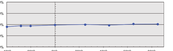
200%
150%
100%
-40°C
-20°C
0°C
20°C
40°C
60°C
80°C
Temperature (ºC)
Leakage Current vs. Temperature
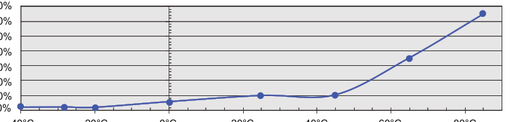
700% 600% 500% 400% 300% 200% 100%
-40°C
-20°C
0°C
20°C
40°C
60°C
80°C
Temperature (ºC)
Equivalent Series Resistance vs. Temperature
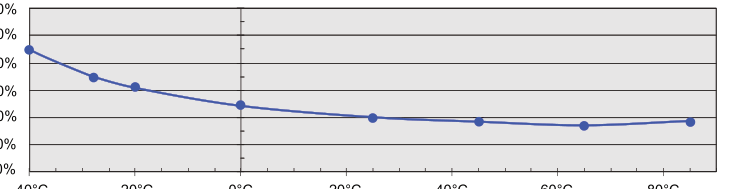
300% 250%
200%
150% 100%
50%
-40°C
-20°C
0°C
20°C
40°C
60°C
80°C
Temperature (°C)
Page 7
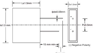
MECHANICAL SPECIFICATIONS
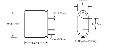
5.4V, 6.0V Shrink Wrap Type - Straight Leads
5.4V, 6.0V Shrink Wrap Type - Bent Leads
D±1.0mm
D±1.0mm
L±1.5mm
L±1.5mm
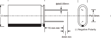
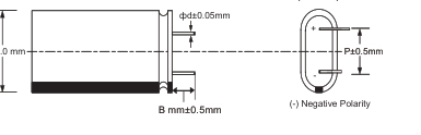
W±1.0 mm
| Cap (F) | D (mm) | W (mm) | L (mm) | P (mm) | d (mm) | B (mm)* |
| 0.47 | 6.3 | 13.6 | 14.0 | 9.0 | 0.6 | 2.0 |
| 0.47 | 8.0 | 16.0 | 14.0 | 11.5 | 0.6 | 2.0 |
| 1 | 8.0 | 16.0 | 18.0 | 11.5 | 0.6 | 2.0 |
| 1.5 | 8.0 | 16.0 | 22.0 | 11.5 | 0.6 | 2.0 |
| 2.5 | 10.0 | 20.0 | 22.0 | 15.5 | 0.6 | 2.0 |
| 5 | 10.0 | 20.0 | 32.0 | 15.5 | 0.6 | 2.0 |
| 5 | 12.5 | 25.0 | 22.0 | 18.0 | 0.6 | 2.0 |
| 7.5 | 12.5 | 25.0 | 32.0 | 18.0 | 0.6 | 2.0 |
| 15 | 16.0 | 32.0 | 33.0 | 23.7 | 0.8 | 2.0 |
\*for version with bent leads
7.5V, 9.0V Shrink Wrap Type - Straight Leads
7.5V, 9.0V Shrink Wrap Type - Bent Leads
D±1.0mm
D±1.0mm
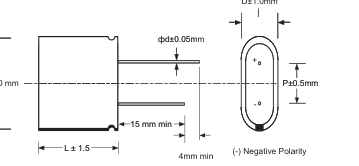
W±1.0 mm
| Cap (F) | D (mm) | W (mm) | L (mm) | P (mm) | d (mm) |
| 0.33 | 8.0 | 24.0 | 14.0 | 13.5 | 0.6 |
| 0.6 | 8.0 | 24.0 | 18.0 | 13.5 | 0.6 |
| 1 | 8.0 | 24.0 | 22.0 | 13.5 | 0.6 |
B (mm)\*
2.0
2.0
2.0
\*for version with bent leads
Page 8
MECHANICAL SPECIFICATIONS
6.0V Plastic Type - Straight Leads
6.0V Plastic Type - Bent Leads
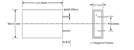
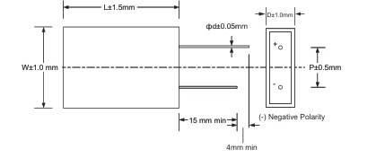
| Cap (F) | D (mm) | W (mm) | L (mm) | P (mm) | d (mm) | B (mm)* |
| 0.47 | 9.5 | 18.5 | 16.0 | 11.5 | 0.6 | 2.0 |
| 1 | 9.5 | 18.5 | 20.0 | 11.5 | 0.6 | 2.0 |
| 1.5 | 9.5 | 18.5 | 24.0 | 11.5 | 0.6 | 2.0 |
\*for version with bent leads
9.0V Plastic Type - Straight Leads
9.0V Plastic Type - Bent Leads
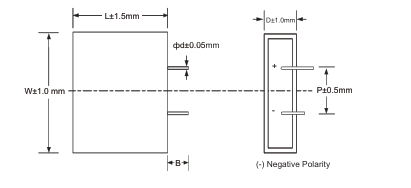
4mm min
| Cap (F) | D (mm) | W (mm) | L (mm) | P (mm) | d (mm) | B (mm)* |
| 0.33 | 9.5 | 26.6 | 16.0 | 11.5 | 0.6 | 2.0 |
| 0.6 | 9.5 | 26.6 | 20.0 | 11.5 | 0.6 | 2.0 |
| 1 | 9.5 | 26.6 | 24.0 | 11.5 | 0.6 | 2.0 |
\*for version with bent leads
Page 9
TEST METHODS
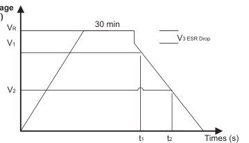
IEC Capacitance Test Method
- Capacitance is measured using a Keithley 2400 or 2602 Meter
- Procedure
- Charge Capacitor to Rated Voltage at room temperature
- Disconnect parts from voltage to remove charging effects
- Discharge cells with a constant current I determined by 4 \* C \* VR
- Noting V1, t1, V2, t2 and performing the calculation for C
Voltage (V)
I – Discharge Current [mA], 4 \* C \* VR VR – Rated Voltage V1 – Initial Test Voltage, 80% of VR V2 – Final Test Voltage, 40% of VR t1 – Initial Test time t2 – Final Test time C = I \* (t2 – t1) / (V1 – V2)
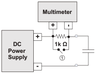
DCL Measurement @ 25°C
- DCL is measured using a Multimeter with high internal impedance across a resistor
- Charge Capacitor to Rated Voltage at room temperature for 72 Hours
- Disconnect parts from Voltage by opening switch 1 (Stabilize for 10 Min)
- Measure Voltage across a known Valued Resistor (1K Ohm)
- Calculate DCL = V/R
Initial ESR Measurement @ 25°C
- Using an Agilent 4263B LCR Meter and a Kelvin connection
- Measure at frequency of 1000 Hz
- Measurement Voltage of 10mV
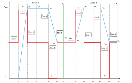
DC ESR Measurement
- Six steps capacity and ESRDC Test Method is used as illus- trated in the figure right.
- Tests are carried out by charging and discharging the capacitor for two cycles at rated voltage and half rated voltage
- C = (CDC1+CDC2) / 2
- ESRDC = (ESRDC1 + ESRDC2) / 2 Where: CDC1 = I2\*(t5-t4)/ (V3-V4) CDC2 = I2\*(t11-t10)/V9-V10)
ESRDC1 = (V5-V4)/I2 ESRDC2 = (V11-V10)/I2 I1 = I2 = 75mA/F
Maximum Operating Current
- This is the maximum current when capacitor temperature rise of the capacitor during its operation is less than 15°C
Maximum Peak Current
- This is the maximum current in less than 1 sec
Watt Density
- Watt Density = (0.12\*V² / RDC) / mass
Energy Density
- Energy density = (½ CV²) / (3600\*mass)
Page 10
POLARITY / REVERSE VOLTAGE
In principal the positive and negative electrodes of the SuperCapacitors are symmetrical and in theory they should not have a polarity but for product consistency and for optimum performance the negative polarity is marked because the capacitors do not discharge completely when in use. It is
recommended that the polarity should be used as marked. If the polarity is reversed the circuit will not have a catastrophic failure but the circuit will see a much higher leakage current for a short duration of time and the life time of the SuperCapacitors will be reduced.
LIFE TIME AND TEMPERATURE PERFORMANCE
The life of a SuperCapacitor is impacted by a combination of operating voltage and the operating temperature according to the following equation: time to failure, t ∞ Vn \* exp (-Q / k\*T) …………..(1) where V is the voltage of operation, Q is the activation energy in electron volts (eV), k is the Boltzmann’s constant in eV and T is the operating temperature in °K (where K is in degrees Kelvin). Typical values for the voltage exponent, n, is between 2.5 - 3.5, and Q is between 1.0 - 1.2 eV in the normal
operating temperature range of 40° to 65°C. The industry standard for SuperCapacitor end of life is when the equivalent series resistance, ESR, increases to 200% of the original value and the capacitance drops by 30%. Typically a SuperCapacitor shows an initial change in the ESR value and then levels off. If the capacitors are exposed to excessive temperatures the ESR will show a continuous degradation In the extreme case, if the temperatures or voltages are substantially higher, than the rated voltage, this will lead to cell leakage or gas leakage and the product will show a faster change in the ESR which may increase to many times the original value.
Expected Lifetime at Various Voltages SCM Series, 5.4V/5.0V, 6.0V/5.5V, 7.5V, 9.0V/8.1V Rated
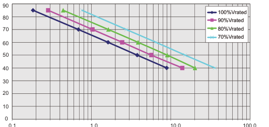
MTTF (years)
Expected Lifetime at Various Voltages SCM Series, 4.6V/4.2V, 6.4V Rated
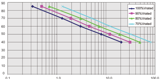
MTTF (years)
Page 11
SOLDERING RECOMMENDATIONS
When soldering SuperCapacitors to a PCB, the temperature & time that the body of the SuperCapacitor sees during soldering can have a negative effect on performance. We advise following these guidelines:
- Do not immerse the SuperCapacitors in solder. Only the leads should come in contact with the solder.
- Ensure that the body of the SuperCapacitor is not in contact with the PCB or other components during soldering. Temperature cycling during soldering may cause the case to shrink or crack, potentially damaging the PCB or other components.
HAND SOLDERING
Keep some distance between the SuperCapacitor body and the tip of the soldering iron; contact between SuperCapacitor body and soldering iron will cause extensive damage to the SuperCapacitor. It is recommended that the soldering iron temperature should be less than 350°C, and contact time should be limited to no more than 4 seconds. Too much exposure to terminal heat during soldering can cause heat to transfer to the body of the SuperCapacitor, potentially damaging the SuperCapacitor.
SAFETY RECOMMENDATIONS
Warnings
- To avoid short circuit, after usage or test, SuperCapacitor voltage needs to discharge to ≤ 0.1V
- Do not apply over-voltage, reverse charge, burn or heat higher than 150°C, explosion-proof valve may break open
- Do not press, damage or disassemble the SuperCapacitor, housing could heat to high temperature causing burns
- If you observe overheating or burning smell from the capacitor disconnect power immediately, and do not touch
Emergency Applications
- If housing is leaking:
- Skin contact: use soap and water thoroughly to wash the area of the skin
- Eye contact: flush with flowing water or saline, and immediately seek medical treatment
- Ingestion: immediately wash with water and seek medical treatment
Transportation
Not subjected to US DOT or IATA regulations UN3499, <10Wh, Non-Hazardous Goods International shipping description – “Electronic Products – Capacitor”
Licensed by CAP-XX
WAVE SOLDERING
Only use wave soldering on Radial type SuperCapacitors. The PCB should be preheated for no longer than 60 seconds, with temperature at, or below, 100°C. Soldering tin should be 0.8mm or thicker.
| Solder Temperature (ºC) | Suggested Solder Time (s) | Maximum Solder Time (s) |
|---|---|---|
| 220 | 7 | 9 |
| 240 | 7 | 9 |
| 250 | 5 | 7 |
| 260 | 3 | 5 |
REFLOW SOLDERING
Infrared or conveyor over reflow techniques can be used on these SuperCapacitors. Do not use a traditional reflow oven without clear rated reflow temperature for SuperCapacitors.
Regulatory
- UL 810A
- RoHS Compliant
- Reach Compliant / Halogen Free
Storage
- Capacitors may be stored within the operating temperature range of the capacitor
- Lower storage temperature is preferred as it extends the shelf life of the capacitor
- Do not store the SuperCapacitors in the following environments
- High temperature / high humidity environments >70°C / 40% RH
- Direct sunlight
- In direct contact with water, salt oil or other chemicals
- In direct contact with corrosive materials, acids, alkalis, or toxic gases
- Dusty environment
- In environment with shock and vibration conditions
Page 12




NORTH AMERICA
EUROPE
ASIA
Tel: +44 1276-697000
Tel: 864-967-2150
SOUTH AMERICA
Tel: +55 11-46881960
Contact:
Tel: +65 6286-7555
JAPAN
Tel: +81 740-321250
http://www.avx.com