
DATASHEET SEARCH SITE
Document overview
- Manufacturer or author: Provided By www.digicamel.com(FREE DATASHEET DOWNLOAD SITE)
- PDF pages: 11
Technical content
Description
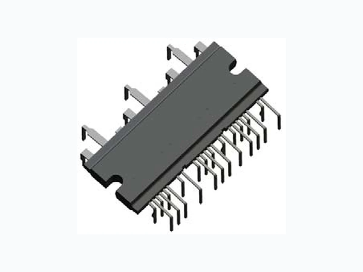
The SCM1101M inverter power module (IPM) device provides a robust, highly-integrated solution for optimally controlling 3-phase motor power inverter systems and variable speed control systems used in energy-conserving designs to drive motors of residential and commercial appliances. These ICs take 85 to 253 V AC input voltage, and 10 A (continuous) output current. They can withstand voltages of up to 600 V (IGBT breakdown voltage). The SCM1100M series employs a new, small-footprint proprietary DIP package. The IC itself consists of all of the necessary power elements (six IGBTs), pre-drive ICs (three), and freewheeling diodes (six), needed to configure the main circuit of an inverter, as well as a bootstrap circuit (three bootstrap diodes and three boot resistors) as a high-side drive power supply. This enables the main circuit of the inverter to be configured with fewer external components than traditional designs. Applications include residential white goods (home appliances) and commercial appliance motor control, such as: ▪ Air conditioner fan motor ▪ Refrigerator compressor motor ▪ Washing machine main motor ▪ Air conditioner compressor motor Features and Benefits ▪ Each half-bridge circuit consists of a pre-driver circuit that is completely independent from the others ▪ Protection against simultaneous high- and low-side turning on ▪ Bootstrap diodes with series resistors for suppressing inrush current are incorporated ▪ CMOS compatible input (3.3 to 5 V) ▪ Designed to minimize simultaneous current through both high- and low-side IGBTs by optimizing gate drive resistors ▪ Integrated Fast Recovery Diode (FRD) as freewheeling diode for each IGBT ▪ UVLO protection with auto restart ▪ Overcurrent protection with off-time period adjustable by an external capacitor ▪ Fault (FO indicator) signal output at protection activation: UVLO (low side only), OCP, and STP ▪ Proprietary power DIP package ▪ UL Recognized Component (File No.: E118037) High Voltage 3-Phase Motor Driver Functional Block Diagram Package: Power DIP Not to scale CFO Drive Circuit UV Detect Drive Circuit Level Shift Input Logic Shoot Through Prevention UV Detect O. C. Protect HVIC HO LO FO COM LIN HIN VCC VB HS VBB U, V, or W LS Figure 1. Diagram of one of three phases in the device.
High Voltage 3-Phase Motor DriverSCM1101M Selection Guide Part Number Packing IGBT Breakdown Voltage, VCES(min) (V) IGBT Saturation Voltage, VCE(sat)(typ) (V) Output Current Continuous, IO(max) (A) Pulsed, IOP (max) (A) SCM1101M 10 pieces per tube 600 1.75 10 20 All performance characteristics given are typical values for circuit or system baseline design only and are at the nominal operating voltage and an ambient temperature, T A, of 25°C, unless oth er wise stated. Absolute Maximum Ratings, valid at TA = 25°C Characteristic Symbol Remarks Rating Units Supply Voltage V DC Between VBB and LS1, LS2, and LS3 450 V Supply Voltage (Surge) V DC(surge) Between VBB and LS1, LS2, and LS3 500 V IGBT Breakdown Voltage V CES VCC = 15 V, IC = 1 mA, VIN = 0 V 600 V Logic Supply Voltage V CC Between VCC and COM 20 V Boot-strap Voltage V BS Between VB and HS (U,V,W) 20 V Output Current, Continuous I O TCase = 25°C 10 Adc TCase = 100°C 5.9 Adc Output Current, Pulsed I OP Pulse Width ≤ 1 ms 20 A Input Voltage V IN –0.5 to 7 V FO Terminal Voltage V FO Between FO and COM 7 V Maximum Allowable Power Dissipation P D TCase = 25°C, 1 element operation (IGBT) 20.8 W TCase = 100°C, 1 element operation (IGBT) 8.3 W Thermal Resistance, Junction-to-Case R(j-c)Q 1 element operation (IGBT) 6 °C/W R(j-c)F 1 element operation (FRD) 6.5 °C/W Case Operation Temperature T COP –20 to 100 °C Junction Temperature (IGBT) T J 150 °C Storage Temperature T stg –40 to 150 °C Isolation Voltage V iso Between exposed thermal pad and each pin; 1 minute, ac 2000 V rms Recommended Operating Conditions Characteristic Symbol Remarks Min. Typ. Max. Units Main Supply Voltage V DC Between VBB and LS – 300 400 V Logic Supply Voltage V CC Between VCC and COM 13.5 – 16.5 V Logic Supply Voltage V BS Between VB and HS 13.5 – 16.5 V Minimum Input Pulse Width tINmin(on) On pulse 0.5 – – μs tINmin(off) Off pulse 0.5 – – μs Dead Time t dead 1.5 – – μs FO Pull-up Resistor R FO 1 – 22 k Ω CFO Capacitor C FO 1 – 10 nF FO Pull-up Voltage V FO 4.5 – 5.5 V Bootstrap Capacitor C BOOT 10 – 220 μF Shunt Resistor R S For IP ≤ 20 A 25.5 – – m Ω PWM Carrier Frequency f C – – 10 kHz Junction Temperature T J – – 125 °C Allegro MicroSystems, Inc.
115 Northeast Cutoff
Worcester, Massachusetts 01615-0036 U.S.A.
High Voltage 3-Phase Motor DriverSCM1101M SCM1100M Cont roller VBB RS CFO RFO CBOOT Drive Circuit UV Detect Drive Circuit Level Shift Input Logic Shoot Through Prevention UV Detect O.C. Protect HVIC 1 HO HS LO LS VB VCC HIN LIN COM FO CFO Drive Circuit UV Detect Drive Circuit Level Shift Input Logic Shoot Through Prevention UV Detect O.C. Protect HVIC2 HO HS LO LS VB VCC HIN LIN COM FO CFO Drive Circuit UV Detect Drive Circuit Level Shift Input Logic Shoot Through Prevention UV Detect O.C. Protect HVIC3 HO HS LO LS VB VCC HIN LIN COM FO CFO CN VFO M CBOOT CBOOT Vcc CS Typical Application Diagram NOTE: ▪ To use the OCP circuit, an external shunt resistor, RS, is needed. The RS value can be obtained from the formula: RS(Ω) = 0.5 (V) / Overcurrent Detection Set Current (A) – 0.0024 (Ω). ▪ To avoid malfunction, the wiring between the LS and COM pins should be as short as possible. ▪ To prevent surge destruction, put a 0.01 to 1 μF snubber capacitor, CS, in parallel with the electrolytic capacitor. ▪ To prevent surge destruction, put a 18 to 20 V Zener diode between the VCC and COM pins. ▪ To prevent surge malfunction, put a 0.01 to 0.1 μF ceramic capacitor between the VCC and COM pins and the VB and HS pins. Allegro MicroSystems, Inc. Worcester, Massachusetts 01615-0036 U.S.A.
High Voltage 3-Phase Motor DriverSCM1101M ELECTRICAL CHARACTERISTICS, valid at TA=25°C, unless otherwise noted Characteristics Symbol Conditions Min Typ Max Units Logic Supply Voltage V CC Between VCC and COM 13.5 – 16.5 V Logic Supply Current I CC VCC = 15 V, 3 phases operating – 5 8 mA Bootstrap Supply Current I BS VB – HS = 15 V, one phase operating – 400 800 μA Input Voltage VIH VCC = 15 V, output on – 2.0 2.5 V VIL VCC = 15 V, output off 1.0 1.5 – V Input Voltage Hysteresis V Ihys VCC = 15 V – 0.5 – V Input Current IIHH VCC = 15 V, VIN = 5 V – 50 100 μA IILH VCC = 15 V, VIN = 0 V – – 2 μA Undervoltage Lock Out (High Side) UVHL VCC = 15 V 10.0 – 12.0 V UVHH 10.5 – 12.5 V Undervoltage Lock Out (Low Side) UVLL VCC = 15 V 10.5 – 12.5 V UVLH 11.0 – 13.0 V FO Terminal Output Voltage VFOL VCC = 15 V, VFO = 5 V, RFO = 10 kΩ – – 0.5 V VFOH 4.8 – – V Overcurrent Protection Trip Voltage V TRIP VCC = 15 V 0.46 0.50 0.54 V Overcurrent Protection Hold Time t P VCC = 15 V, CFO = 0.0022 μF2 – – m s Blanking Time t blank VCC = 15 V – 2 – μs IGBT Breakdown Voltage V CES VCC = 15 V, IC = 250 μA, VIN = 0 V 600 – – V IGBT Leakage Current I CES VCC = 15 V, VCE = 600 V, VIN = 0 V – – 1 mA IGBT Saturation Voltage V CE(sat) VCC = 15 V, IC = 10 A, VIN = 5 V – 1.75 2.2 V Diode Forward Voltage V F VCC = 15 V, IF = 10 A, VIN = 0 V – 1.7 2.2 V Diode Recovery Time (Bootstrap) t rr IF / IRP = 100 mA/100 mA – 70 – ns Diode Leakage Current (Boot Strap) I IB VR = 600 V – 5 10 μA Diode Forward Voltage (Boot Strap) V FB IF = 0.15 A – 1.1 1.3 V Diode Series Resistor (Boot Strap) R B 17.6 22.0 26.4 Ω High Side Switching Time tdH(on) VDC = 300 V, VCC = 15 V, IC = 10 A, inductive load; HIN = 05 V or 50 V – 320 – ns trH –5 0–n s trrH –8 0–n s tdH(off) – 560 – ns tfH – 210 – ns Low Side Switching Time tdL(on) VDC = 300 V, VCC = 15 V, IC = 10 A, inductive load; LIN = 05 V or 50 V – 350 – ns trL –8 0–n s trrL – 140 – ns tdL(off) – 610 – ns tfL – 200 – ns Input Output Truth Table HIN LIN OUT L L High Z LHL HLH H H High Z High Z = High Impedance VIN 10% 90% IC VCE 10% 90% t(off) tftr trr td(off) t(on) td(on) Switching Timing Definitions Allegro MicroSystems, Inc. Worcester, Massachusetts 01615-0036 U.S.A.
High Voltage 3-Phase Motor DriverSCM1101M Timing Diagrams HIN LIN VB -HS HO LO FO UVHL UVHH * Start from positive edge after UVLO release . *VCC =1 5V * No output at H-side UVLO HIN LIN VCC HO LO FO UVLL UVLH *V B -H S= 1 5V * Start from positive edge after UVLO release HIN LIN HO LO FO *VCC ,VB- HS = 15 V * While both HIN and LIN are in high state HO and LO turn off and FO signals out VCC LIN VB-HS LS FO VCC BlankingTime (2 μs typ.) CFO OCP Assist Timer (2 μs min.) Vrc (3.5 V typ.) The slope depends on CFO capacitance * Off operation of all phases can be done by wired OR system with the three FO pins short circuited IGBT turns off softly after overcurrent condition is detected High-Side Driver Input/Output Low-Side Driver Input/Output Shoot-Through Prevention Overcurrent Protection Allegro MicroSystems, Inc. Worcester, Massachusetts 01615-0036 U.S.A.
High Voltage 3-Phase Motor DriverSCM1101M Pin-out Diagram Branded Side 3325 124 Terminal List Table Name Number Function
1 FO1 U phase fault output for overcurrent and UVLO detected
2 CFO1 Capacitor for U phase overcurrent protection hold time
3 LIN1 Signal input for low-side U phase (active high)
4 COM1 Supply ground for U phase IC
5 HIN1 Signal input for high-side U phase (active high)
6 VCC1 Supply voltage for U phase IC
7 VB1 High-side floating supply voltage for U phase
8 HS1 High-side floating supply ground for U phase
9 FO2 V phase fault output for overcurrent and UVLO detected
10 CFO2 Capacitor for V phase overcurrent protection hold time
11 LIN2 Signal input for low-side V phase (active high)
12 COM2 Supply ground for V phase IC
13 HIN2 Signal input for high-side V phase (active high)
14 VCC2 Supply voltage for V phase IC
15 VB2 High-side floating supply voltage for V phase
16 HS2 High-side floating supply ground for V phase
17 FO3 W phase fault output for overcurrent and UVLO detected
18 CFO3 Capacitor for W phase overcurrent protection hold time
19 LIN3 Signal input for low-side W phase (active high)
20 COM3 Supply ground for W phase IC
21 HIN3 Signal input for high-side W phase (active high)
22 VCC3 Supply voltage for W phase IC
23 VB3 High-side floating supply voltage for W phase
24 HS3 High-side floating supply ground for W phase
25 VBB Positive DC bus supply voltage
26 W Output for W phase
27 LS3 Negative DC bus supply ground for W phase
28 VBB Cut-pin ( positive DC bus supply voltage)
29 V Output for V phase
30 LS2 Negative DC bus supply ground for V phase
31 VBB Cut-pin ( positive DC bus supply voltage)
32 U Output for U phase
33 LS1 Negative DC bus supply ground for U phase
(Bottom View) Allegro MicroSystems, Inc. Worcester, Massachusetts 01615-0036 U.S.A.
High Voltage 3-Phase Motor DriverSCM1101M Leadframe plating Pb-free. Device composition complies with the RoHS directive. Branding codes (exact appearance at manufacturer discretion): Section A, type: SCM1101M Section B, lot: YMDDT Where: Y is the last digit of the year of manufacture M is the month (1 to 9, O, N, D) DD is the date T is the tracking letter (A to Z)Leadform: 2552 Dimensions in millimeters (Top View) (Bottom View) PACKAGE OUTLINE DRAWING Allegro MicroSystems, Inc. Worcester, Massachusetts 01615-0036 U.S.A.
High Voltage 3-Phase Motor DriverSCM1101M Characteristic Remarks Min. Typ. Max. Units Heatsink Mounting Screw Torque Use one M3 screw each end 58.8 – 78.4 N•cm 6.0 – 8.0 kgf•cm Flatness of Heatsink Attachment Area Refer to figure below (aaa) –50 – 100 μm Package Weight – 13.5 – g (Top View) aaa A aaa B A B MECHANICAL CHARACTERISTICS Allegro MicroSystems, Inc. Worcester, Massachusetts 01615-0036 U.S.A.
High Voltage 3-Phase Motor DriverSCM1101M PACKING SPECIFICATION Maximum 5 tubes in Y direction Maximum 5 tubes in Z direction Maximum pieces per carton: 10 pieces per tube 5 rows of tubes x 5 layers of tubes 250 pieces per carton Dimensions in millimeters Tube type SCM-A Maximum 10 pieces per tube Pins aligned along X direction Rubber plug at each end Allegro MicroSystems, Inc. Worcester, Massachusetts 01615-0036 U.S.A.
High Voltage 3-Phase Motor DriverSCM1101M WARNING — These devices are designed to be operated at lethal voltages and energy levels. Circuit designs that embody these components must conform with applicable safety requirements. Pre cau tions must be taken to prevent accidental contact with power-line potentials. Do not connect ground ed test equipment. The use of an isolation transformer is recommended during circuit development and breadboarding. Because reliability can be affected adversely by improper storage environments and handling methods, please observe the following cautions. Cautions for Storage
- Ensure that storage conditions comply with the standard temperature (5°C to 35°C) and the standard relative humidity (around 40 to 75%); avoid storage locations that experience extreme changes in temperature or humidity.
- Avoid locations where dust or harmful gases are present and avoid direct sunlight.
- Reinspect for rust on leads and solderability of product that has been stored for a long time. Cautions for Testing and Handling When tests are carried out during inspection testing and other standard test periods, protect the product from power surges from the testing device, shorts between adjacent product packages, and shorts to the heatsink. Remarks About Using Silicone Grease with a Heatsink
- Ensure there are no foreign objects between the heatsink and thermal pad; only silicone thermal grease is allowed.
- When silicone grease is used in mounting this product with a heatsink, grease shall be applied evenly and thinly. If more silicone grease than required is applied, it may produce stress.
- Volatile-type silicone greases may permeate the product and produce cracks after long periods of time, resulting in reduced heat radiation effect, and possibly shortening the lifetime of the product.
- Hard silicone greases may cause cracks in the product when screwing the product to a heatsink.
- Our recommended silicone greases for heat radiation purposes, which will not cause any adverse effect on the product life, are indicated below: Type Suppliers G746 Shin-Etsu Chemical Co., Ltd. YG6260 Momentive Performance Materials SC102 Dow Corning Toray Silicone Co., Ltd. Soldering
- When soldering the product, please be sure to minimize the working time, within the following limits: 260±5°C 10 s 380±5°C 5 s
- Soldering iron should be at a distance of at least 1.5 mm from the body of the product Electrostatic Discharge
- When handling the product, operator must be grounded. Grounded wrist straps worn should have at least 1 MΩ of resistance to ground to prevent shock hazard.
- Workbenches where the product is handled should be grounded and be provided with conductive table and floor mats.
- When using measuring equipment such as a curve tracer, the equipment should be grounded.
- When soldering the product, the head of soldering irons or the solder bath must be grounded in other to prevent leak voltages generated by them from being applied to the product.
- The product should always be stored and transported in our shipping containers or conductive containers, or be wrapped in aluminum foil. Allegro MicroSystems, Inc.
Worcester, Massachusetts 01615-0036 U.S.A.
High Voltage 3-Phase Motor DriverSCM1101M Copyright ©2007-2010 Allegro MicroSystems, Inc. This datasheet is based on Sanken datasheet SSJ-03459 The products described herein are manufactured in Ja pan by Sanken Electric Co., Ltd. for sale by Allegro MicroSystems, Inc. Sanken and Allegro reserve the right to make, from time to time, such de par tures from the detail spec i fi ca tions as may be re quired to per mit im- prove ments in the per for mance, reliability, or manufacturability of its prod ucts. Therefore, the user is cau tioned to verify that the in for ma tion in this publication is current before placing any order. When using the products described herein, the ap pli ca bil i ty and suit abil i ty of such products for the intended purpose shall be reviewed at the users responsibility. Although Sanken undertakes to enhance the quality and reliability of its prod ucts, the occurrence of failure and defect of semi con duc tor products at a certain rate is in ev i ta ble. Users of Sanken products are requested to take, at their own risk, preventative measures including safety design of the equipment or systems against any possible injury, death, fires or damages to society due to device failure or malfunction. Sanken products listed in this publication are designed and intended for use as components in general-purpose electronic equip ment or apparatus (home ap pli anc es, office equipment, tele com mu ni ca tion equipment, measuring equipment, etc.). Their use in any application requiring radiation hardness assurance (e.g., aero space equipment) is not supported. When considering the use of Sanken products in ap pli ca tions where higher reliability is re quired (transportation equipment and its control systems or equip ment, fire- or burglar-alarm systems, various safety devices, etc.), contact a company sales representative to discuss and obtain written con- firmation of your spec i fi ca tions. The use of Sanken products without the written consent of Sanken in applications where ex treme ly high reliability is required (aerospace equip- ment, nuclear power-control stations, life-support systems, etc.) is strictly prohibited. The information in clud ed herein is believed to be accurate and reliable. Ap pli ca tion and operation examples described in this pub li ca tion are given for reference only and Sanken and Allegro assume no re spon si bil i ty for any in fringe ment of in dus tri al property rights, intellectual property rights, or any other rights of Sanken or Allegro or any third party that may result from its use. Anti radioactive ray design is not considered for the products listed herein. The contents in this document must not be transcribed or copied without Sanken’s written consent. Allegro MicroSystems, Inc. Worcester, Massachusetts 01615-0036 U.S.A.