


 Download PDF
DATASHEET SEARCH SITE
Document overview
- PDF pages: 2
Technical content
Page 1
SBX2540-3G
SBX2540-3G
Schottky Barrier Rectifier Diodes 3rd Generation Schottky-Gleichrichterdioden 3. Generation
Version 2018-09-28
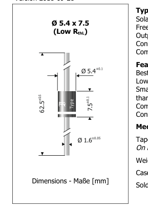
Typical Applications
IFAV = 25 A
VRRM = 40 V
VF@5A < 0.45 V
IFSM = 290/330 A
Tjmax = 150°C
VF125 ~ 0.25 V @ 5 A
Typische Anwendungen
Solar Bypass Diodes, Polarity Protection, Free-wheeling diodes, Output Rectification in DC/DC Converters Commercial grade 1)
Features
Best trade-off between VF and IR 2) Lowest RthL for lowest Tj Smaller package outline than SBX2540 Compliant to RoHS, REACH, Conflict Minerals 1)
Mechanical Data 1)
Taped in ammo pack
Solar-Bypassdioden, Verpolschutz, Freilaufdioden, Ausgangsgleichrichtung in Gleichstromwandlern Standardausführung 1)
Besonderheiten
Optimale Auswahl von VF und IR 2) Niedrigster RthL für niedrigstes Tj Halogen
Gehäusegröße kleiner
FREE
als SBX2540
Konform zu RoHS, REACH,
Pb
Konfliktmineralien 1)
Mechanische Daten 1)
500
Gegurtet in Ammo-Pack
Auf Anfrage: auf 13” Rolle
Gewicht ca.
Gehäusematerial
Löt- und Einbaubedingungen
Maximum ratings 3)
Grenzwerte 3)
Type Typ
SBX2540-3G
| Max. average forward rectified current, R-load T = 50°C Dauergrenzstrom in Einwegschaltung mit R-Last A | I FAV | 25 A 4) |
|---|---|---|
| Peak forward surge current, Half sine-wave 50 Hz (10 ms) Stoßstrom in Fluss-Richtung Sinus-Halbwelle 60 Hz (8.3 ms) | I FSM | 290 A 330 A |
| Rating for fusing, t < 10 ms Grenzlastintegral, t < 10 ms | i2t | 420 A2s |
| Junction temperature – Sperrschichttemperatur in DC forward mode – bei Gleichstrom-Durchlassbetrieb | T j T j | -50...+150°C ≤ 200°C 2,5) |
| Storage temperature Lagerungstemperatur | T S | -50...+175°C |
1 Please note the detailed information on our website or at the beginning of the data book Bitte beachten Sie die detaillierten Hinweise auf unserer Internetseite bzw. am Anfang des Datenbuches 2 For more details, ask for the Diotec Application Note “Reliability of Bypass Diodes” Weitere Infos in der Diotec Applikationsschrift „Reliability of Bypass Diodes” TA = 25°C unless otherwise specified – TA = 25°C wenn nicht anders angegeben Valid, if leads are kept at ambient temperature at a distance of 10 mm from case Gültig, wenn die Anschlussdrähte in 10 mm Abstand vom Gehäuse auf Umgebungstemperatur gehalten werden Meets the Requirements of IEC 61215 bypass diode thermal test
Erfüllt die Anforderungen des IEC 61215 Bypass-Diodentests
© Diotec Semiconductor AG
http://www.diotec.com/
Page 2
Characteristics
Type
Forward voltage
Forward voltage
Typ
Durchlass-Spannung
Durchlass-Spannung
VF [V] @ IF [A] @ Tj
VF [V] @ IF [A] @ Tj
SBX2540-3G
typ. 0.25
5 125°C < 0.45 5 25°C
SBX2540-3G
Kennwerte
Forward voltage Durchlass-Spannung
VF [V] @ IF [A] @ Tj
< 0.57 25 25°C
| Leakage current T = 25°C j V = V Sperrstrom T = 100°C R RRM j | I R | < 200 µA typ. 10 mA |
|---|---|---|
| Typical junction capacitance – Typische Sperrschichtkapazität V = 4 V R | C j | 720 pF |
| Typical thermal resistance junction to ambient Typischer Wärmewiderstand Sperrschicht – Umgebung | R thA | < 10 K/W 1) |
| Typical thermal resistance junction to lead (at the case) Typischer Wärmewiderstand Sperrschicht-Anschlussdraht (am Gehäuse) | R thL | < 2.1 K/W 2) |
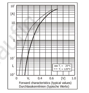
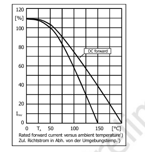
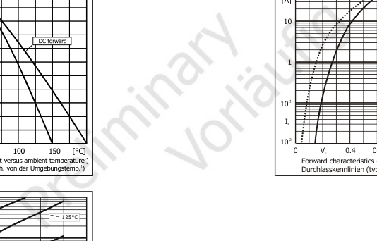
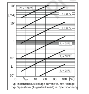
Disclaimer: See data book page 2 or website Haftungssauschluss: Siehe Datenbuch Seite 2 oder Internet
Valid, if leads are kept at ambient temperature at a distance of 10 mm from case Gültig, wenn die Anschlussdrähte in 10 mm Abstand vom Gehäuse auf Umgebungstemperatur gehalten werden Valid, if leads are kept at ambient temperature at a distance of 3 mm from case Gültig, wenn die Anschlussdrähte in 3 mm Abstand vom Gehäuse auf Umgebungstemperatur gehalten werden
http://www.diotec.com/
© Diotec Semiconductor AG