

 Download PDF
S9066-111 HAMAMATSU
Document overview
- PDF pages: 2
Technical content
Page 1
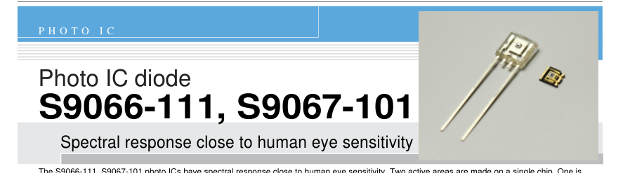
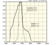
The S9066-111, S9067-101 photo ICs have spectral response close to human eye sensitivity. Two active areas are made on a single chip. One is for detecting light in the visible to near infrared range and the other is only sensitive to near infrared light and used for output signal correction. Almost only the visible range can be measured by finding the difference between the two output signals in the internal current amplifier circuit. Compared to previously available devices, these photo ICs offer lower output fluctuations for light sources producing the same illuminance at different color temperatures.

l Large output current equivalent to phototransistors
l Various types of light level measurement
l Lower output-current fluctuations l Excellent linearity l Low output fluctuations for light sources producing the same illuminance at different color temperatures
I Absolute maximum ratings (Ta=25 °C)
| Parameter | Symbol | S9066-111 | S9067-101 | Unit |
|---|---|---|---|---|
| Reverse voltage | VR | -0.5 to 12 | V | |
| Photocurrent | IL | 5 | mA | |
| Forward current | IF | 5 | mA | |
| Power dissipation *1 | P | 250 | 150 | mW |
| Operating temperature | Topr | -30 to +80 | °C | |
| Storage temperature | Tstg | -40 to +85 | °C | |
\*1: Derate power dissipation at a rate of the following rate above Ta=25 °C. S9066-111: -3.3 mW/°C, S9067-101: -2.0 mW/°C
I Electrical and optical characteristics (Ta=25 °C)

Page 2
Photo IC diode S9066-111, S9067-101
I Dark current vs. ambient temperature
I Spectral response
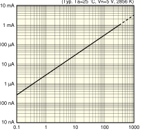
I Linearity (S9066-111)
(Typ. Ta=25 ˚C, VR=5 V)
(Typ. Ta=25 ˚C, VR=5 V, 2856 K)
WAVELENGTH (nm)
ILLUMINANCE (lx)
KPICB0083EB
KPICB0078EC
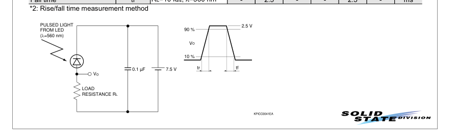
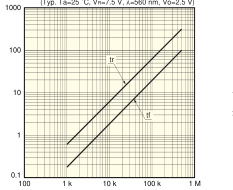
I Rise/fall times vs. load resistance I Operating circuit example
(Typ. Ta=25 ˚C, VR=7.5 V, λ=560 nm, Vo=2.5 V)
PHOTODIODE
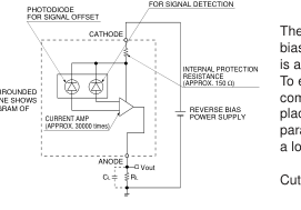
THE DRAWING SURROUNDED BY THE DOTTED LINE SHOWS A SCHEMATIC DIAGRAM OF THE PHOTO IC.
LOAD RESISTANCE (Ω)
KPICC0091EB
KPICB0115EA
I Dimensional outlines (unit: mm)
S9066-111
(Typ. VR=5 V)
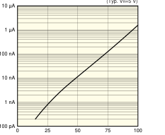
AMBIENT TEMPERATURE (˚C)
KPICB0076EB
The photo IC diode must be reverse-
biased so that a positive potential
is applied to the cathode.
To eliminate high-frequency
components, we recommend
placing a load capacitance CL in
parallel with load resistance RL as
a low-pass filter.
.. 1
Cut-off frequency fc = 2πCLRL
S9067-101
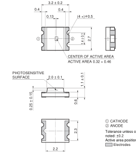
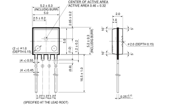
PHOTOSENSITIVE
ANODE
SURFACE
(ANODE) NC
10˚ 10˚
CATHODE Tolerance unless otherwise noted: ±0.1, ±2˚ Shaded area indicates burr.
Active area position accuracy: X, Y£±0.3
Values in parentheses indicate reference value.
5˚ 5˚
KPICA0050EE
KPICA0051EC
Information furnished by HAMAMATSU is believed to be reliable. However, no responsibility is assumed for possible inaccuracies or omissions. Specifications are subject to change without notice. No patent rights are granted to any of the circuits described herein. ©2008 Hamamatsu Photonics K.K.
HAMAMATSU PHOTONICS K.K., Solid State Division
1126-1 Ichino-cho, Higashi-ku, Hamamatsu City, 435-8558 Japan, Telephone: (81) 53-434-3311, Fax: (81) 53-434-5184, www.hamamatsu.com U.S.A.: Hamamatsu Corporation: 360 Foothill Road, P.O.Box 6910, Bridgewater, N.J. 08807-0910, U.S.A., Telephone: (1) 908-231-0960, Fax: (1) 908-231-1218 Germany: Hamamatsu Photonics Deutschland GmbH: Arzbergerstr. 10, D-82211 Herrsching am Ammersee, Germany, Telephone: (49) 08152-3750, Fax: (49) 08152-2658 France: Hamamatsu Photonics France S.A.R.L.: 19, Rue du Saule Trapu, Parc du Moulin de Massy, 91882 Massy Cedex, France, Telephone: 33-(1) 69 53 71 00, Fax: 33-(1) 69 53 71 10 United Kingdom: Hamamatsu Photonics UK Limited: 2 Howard Court, 10 Tewin Road, Welwyn Garden City, Hertfordshire AL7 1BW, United Kingdom, Telephone: (44) 1707-294888, Fax: (44) 1707-325777
North Europe: Hamamatsu Photonics Norden AB: Smidesvägen 12, SE-171 41 Solna, Sweden, Telephone: (46) 8-509-031-00, Fax: (46) 8-509-031-01 Italy: Hamamatsu Photonics Italia S.R.L.: Strada della Moia, 1/E, 20020 Arese, (Milano), Italy, Telephone: (39) 02-935-81-733, Fax: (39) 02-935-81-741