

 Download PDF
S8745-01 HAMAMATSU
Document overview
- PDF pages: 5
Technical content
Page 1
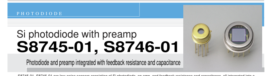
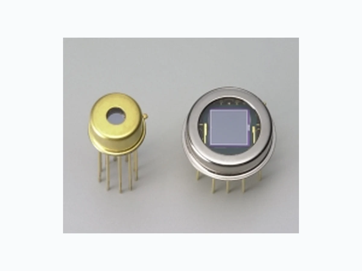
S8745-01, S8746-01 are low-noise sensors consisting of Si photodiode, op amp, and feedback resistance and capacitance, all integrated into a small package. By simply connecting to a power supply, S8745-01 and S8746-01 can be used in low-light-level measurement such as analytical equipment and measurement equipment. The active area of the photodiode is internally connected to the GND terminal making it highly resistant to EMC noise.

S8745-01: TO-5 S8746-01: TO-8 l Active area S8745-01: 2.4 × 2.4 mm S8746-01: 5.8 × 5.8 mm l FET input operational amplifier with low power dissipation l Built-in Rf=1 GΩ and Cf=5 pF l Variable gain with an externally connected resistor l Low noise and NEP l Package with shielding effect l Resistant to EMC noise
S8745-01, S8746-01 may be damaged by Electro Static Discharge, etc. Please see Precautions for use in the last page. I Absolute maximum ratings (Ta=25 °C)
| Parameter | Symbol | Value | Unit |
|---|---|---|---|
| Supply voltage (op amp) | Vcc | ±20 | V |
| Power dissipation | P | 500 | mW |
| Operating temperature | Topr | -20 to +60 | °C |
| Storage temperature | Tstg | -30 to +80 | °C |
I Electrical and optical characteristics (Typ. Ta=25 °C, Vcc=±15 V, RL=1 MΩ, unless otherwise noted)
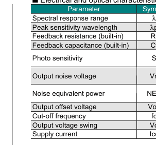
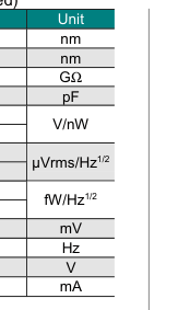
| Symbol | Condition | S8745-01 | S8746-01 |
|---|---|---|---|
| λ | 190 to 1100 | ||
| λp | 960 | ||
| Rf | 1 | ||
| Cf | 5 | ||
| S | λ=200 nm | 0.12 | |
| λ=λp | 0.52 | ||
| Vn | Dark state f=10 Hz | 6 | 7 |
| Dark state, f=20 Hz | 5 | 6 | |
| NEP | λ=λp, f=10 Hz | 11 | 15 |
| λ=λp, f=20 Hz | 11 | 15 | |
| Vos | Dark state | ±4 | |
| fc | -3 dB | 32 | |
| Vo | 13 | ||
| Icc | Dark state | 0.3 | |

Page 2
Figure 1 Spectral response
S8745-01, S8746-01
[Typ.Ta=25 ˚C, Rf=1 GΩ (built-in), Cf=5 pF (built-in)] 0.6
0.5
0.4
0.3
0.2
0.1
0 190 400 600 800 1000 1200
WAVELENGTH (nm)
KSPDB0232EA
The built-in feedback resistance and capacitance of S8745-
01 and S8746-01 are 1 GΩ and 5 pF, respectively. This
combination provides a sensitivity of about 0.1 to 0.5 V/nW in
the wavelength range of 190 to 1100 nm.
Figure 2 Gain-frequency characteristics
S8745-01
[Typ. Ta=25 ˚C, Vcc=±15 V, Cf=5 pF (built-in), RL=1 MΩ] 104 S8745-01
+111 MΩ
103
(EXTERNAL CONNECTED) +11 MΩ (EXTERNAL
102
CONNECTED)
101
100
+1 MΩ (EXTERNAL CONNECTED)
10-1
10-2 0.01 0.1 1 10 100
FREQUENCY (kHz)
KSPDB0233EA
S8746-01
[Typ. Ta=25 ˚C, Vcc=±15 V, Cf=5 pF (built-in), RL=1 MΩ] 104 S8746-01
+111 MΩ
103
(EXTERNAL CONNECTED) +11 MΩ
102
(EXTERNAL CONNECTED)
101
100
+1 MΩ (EXTERNAL CONNECTED)
10-1
10-2 0.01 0.1 1 10 100
FREQUENCY (kHz)
KSPDB0234EA
The current-to-voltage conversion gain can be varied by connecting an external feedback resistor between pins 4 and 6
for S8745-01, and between pins 9 and 12 for S8746-01 (see figure 5). Figure 2 shows the frequency response
characteristics of S8745-01 and S8746-01 with or without an externally connected feedback resistor. Because S8745-01
and S8746-01 have a built-in resistor of 1 GΩ, for example the total feedback resistance will be converted to 100 MΩ by
externally connecting a resistor of 111 MΩ. Choose the desired constant according to the incident light level to be
detected.
Note) If the external feedback resistor is 1 MΩ or less, gain peaking may occur in the frequency response. Therefore, be sure to
connect a matched feedback capacitor for phase compensation.
Page 3
Figure 3 Output noise voltage vs. frequency
S8745-01
[Typ. Ta=25 ˚C, Vcc=±15 V, Cf=5 pF (built-in), RL=1 MΩ, dark state] 100
+111 MΩ S8745-01 (EXTERNAL
10
CONNECTED)
+11 MΩ (EXTERNAL CONNECTED)
1
0.1 +1 MΩ (EXTERNAL CONNECTED)
0.01
1 10 100 1000
0.001 0.01
0.1
FREQUENCY (kHz)
KSPDB0235EA
S8746-01
[Typ. Ta=25 ˚C, Vcc=±15 V, Cf=5 pF (built-in), RL=1 MΩ, dark state] 100
S8746-01 +111 MΩ (EXTERNAL
10
CONNECTED)
1
0.1
+1 MΩ
+11 MΩ
(EXTERNAL
(EXTERNAL
CONNECTED)
CONNECTED)
0.01
1 10 100 1000
0.001 0.01
0.1
FREQUENCY (kHz)
KSPDB0236EA
Output noise voltage and NEP (noise equivalent power) characteristics allow you to check whether the device can detect the lowlevel light you want to measure. Since NEP is given by the equation (1) as shown at the right, NEP at wavelengths other than λp can
be easily calculated from Figure 1 and Figures 4.
Note) When S8745-01 and S8746-01 are used only with the internal current-to-voltage gain, it is recommended that the "-IN" lead (pin 6 for S8745- 01; pin 9 for S8746-01) be cut off to a short length in order to reduce the influence of external noise as much as possible.
NEP(f, λp) · S (λp)
Vn (f)
- ·· (1)
NEP (f, λ) =
= S (λ)
GI - V (f) · Ssi (λ)
NEP (f, λ) : NEP at frequency and wavelength to be detected
NEP (f, λp): NEP at peak wavelength (See Figures 4)
GI-V(f)
: Current-to-voltage conversion gain (See Figure 2)
Ssi (λ)
: Sensitivity of Si photodiode
S (λ)
: Sensitivity of S8745-01 and S8746-01 (See Figure 1.)
: Sensitivity of S8745-01 and S8746-01 at peak wavelength, 0.5 V/nW
S (λp) Vn (f)
: Output noise voltage (See Figure 3)
Figure 4 NEP vs. frequency
S8745-01
[Typ. Ta=25 ˚C, Vcc=±15 V, Cf=5 pF (built-in), RL=1 MΩ, dark state, l=lp] 106
+1 MΩ (EXTERNAL
105
CONNECTED)
+11 MΩ
104
(EXTERNAL CONNECTED)
+111 MΩ
103
(EXTERNAL CONNECTED)
102
S8745-01
101 0.001 0.01
0.1 1 10 100 1000
FREQUENCY (kHz)
KSPDB0237EA
S8746-01
[Typ. Ta=25 ˚C, Vcc=±15 V, Cf=5 pF (built-in), RL=1 MΩ, dark state, l=lp] 106
+1 MΩ (EXTERNAL CONNECTED)
105
+11 MΩ (EXTERNAL CONNECTED)
104
+111 MΩ (EXTERNAL CONNECTED)
103
102
S8746-01
101 0.001 0.01
0.1 1 10 100 1000
FREQUENCY (kHz)
KSPDB0238EA
Page 4
Figure 5 Application circuit example
Vcc+
0.1 µF
TO-5 PACKAGE
Cf=5 pF (BUILT-IN)
-
PHOTODIODE
WINDOW (QUARTZ)
+
0.1 µF
NC Vcc-
Vcc+
0.1 µF
TO-8 PACKAGE
S8745-01
Rf (EXTERNAL CONNECTED)
Rf=1 GΩ (BUILT-IN)
RL
RL is the input impedance to the next-stage circuit when viewed from the OUT terminal.
KSPDC0048EA
S8746-01
Rf (EXTERNAL CONNECTED)
Rf=1 GΩ (BUILT-IN)
Cf=5 pF (BUILT-IN)
-
PHOTODIODE
WINDOW (QUARTZ)
+
RL
RL is the input impedance to the next-stage circuit when viewed from the OUT terminal.
0.1 µF
NC Vcc-
KSPDC0049EA
S8745-01 and S8746-01 use a package with the guard ring effect provided. To make it effective during measurement, the
package leads (pin 5 for S8745-01; pins 5 and 11 for S8746-01) should be connected to the ground line.
When a feedback resistor is externally connected, it is necessary to provide a guard ring on the circuit board or to provide a teflon
standoff for the leads.
Note) A tantalum or ceramic capacitor of 0.1 to 10 µF must be connected to the supply voltage leads (pins 3 and 9 for S8745-01;
pins 1 and 4 for S8746-01) as a bypass capacitor used to prevent the device from oscillation.
Page 5
Figure 6 Dimensional outlines (unit: mm)
➀ S8745-01
➁ S8746-01
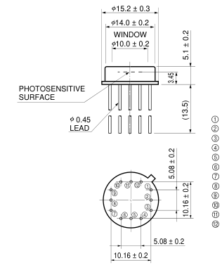
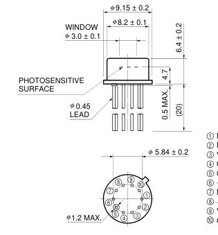
Vcc+ NC NC
NC
Vcc-
NC
CASE
Vcc+
+IN
OUT
NC
CASE
NC
-IN
-IN
NC
GND
+IN
CASE
Vcc-
OUT
GND
BOTTOM VIEW
BOTTOM VIEW
KSPDA0158EA
KSPDA0159EA
Information furnished by HAMAMATSU is believed to be reliable. However, no responsibility is assumed for possible inaccuracies or omissions. Specifications are subject to change without notice. No patent rights are granted to any of the circuits described herein. ©2004 Hamamatsu Photonics K.K.
HAMAMATSU PHOTONICS K.K., Solid State Division 1126-1 Ichino-cho, Higashi-ku, Hamamatsu City, 435-8558 Japan, Telephone: (81) 53-434-3311, Fax: (81) 53-434-5184, http://www.hamamatsu.com U.S.A.: Hamamatsu Corporation: 360 Foothill Road, P.O.Box 6910, Bridgewater, N.J. 08807-0910, U.S.A., Telephone: (1) 908-231-0960, Fax: (1) 908-231-1218 Germany: Hamamatsu Photonics Deutschland GmbH: Arzbergerstr. 10, D-82211 Herrsching am Ammersee, Germany, Telephone: (49) 08152-3750, Fax: (49) 08152-2658 France: Hamamatsu Photonics France S.A.R.L.: 19, Rue du Saule Trapu, Parc du Moulin de Massy, 91882 Massy Cedex, France, Telephone: 33-(1) 69 53 71 00, Fax: 33-(1) 69 53 71 10
United Kingdom: Hamamatsu Photonics UK Limited: 2 Howard Court, 10 Tewin Road, Welwyn Garden City, Hertfordshire AL7 1BW, United Kingdom, Telephone: (44) 1707-294888, Fax: (44) 1707-325777 North Europe: Hamamatsu Photonics Norden AB: Smidesvägen 12, SE-171 41 Solna, Sweden, Telephone: (46) 8-509-031-00, Fax: (46) 8-509-031-01 Italy: Hamamatsu Photonics Italia S.R.L.: Strada della Moia, 1/E, 20020 Arese, (Milano), Italy, Telephone: (39) 02-935-81-733, Fax: (39) 02-935-81-741
Cat. No. KSPD1065E01 Dec. 2004 DN