
S5A LEIDITECH
Document overview
- Manufacturer or author: Provided By www.digicamel.com(FREE DATASHEET DOWNLOAD SITE)
- PDF pages: 3
Technical content
Features
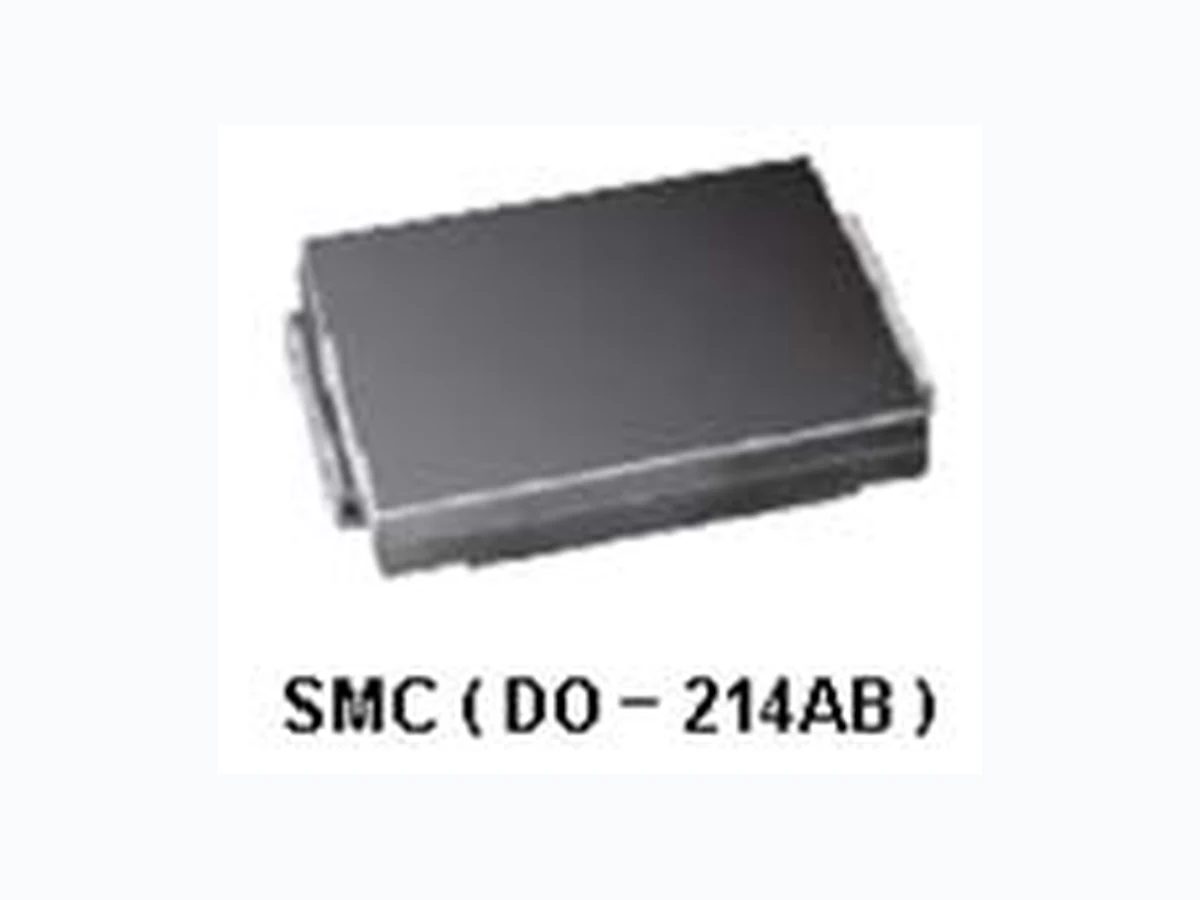
Ideal for automated placement Glass passivated chip junctions Low forward voltage drop Low leakage current High forward surge capability High temperature soldering 260℃/10 seconds at terminals Component in accordance to RoHS 2002/95/1 and WEEE 2002/96/EC Major Ratings and Characteristics Mechanical Date Case: JEDEC DO-214AB molded plastic body over glass passivated chip Terminals: Solder plated, solderable per JESD22 B102 I F(AV) 5.0 A V RRM
50 V to 1000 V
I FSM 100 A I R 5 μA V F 1.1 V JESD22 B102 Polarity: Laser band denotes cathode end Maximum Ratings & Thermal Characteristics A = 25 °C unless otherwise noted)
Electrical Characteristics
A = 25 °C unless otherwise noted) Note 2: Pulse test:300μs pulse width,1% duty cycle. V F 1.1 V T j max. 150 °C S5J S5K S5M UNIT Maximum repetitive peak reverse voltage V RRM 50 100 200 400 Items Symbol S5A S5B S5D S5G 600 800 1000 V Maximum RMS voltage V RMS 35 70 140 280 420 560 700 V Maximum DC blocking voltage V DC 50 100 200 400 600 800 1000 V Maximum average forward rectified current I F(AV) Peak forward surge current 8.3 ms single half sine-wave superimposed on rated load I FSM 100 A Thermal resistance from junction to lead (1) R θJL 20 ℃/ W Operating junction and storage temperature range T J , T STG –55 to +150 ℃ Max UNIT Instantaneous forward voltage I F =5A (2) V F - 0.98 1.10 V Items Test conditions Symbol Min Type 50 μA Typical junction capacitance 4.0 V ,1MHz C J - 60.0 - pF Reverse current V R DC T j =25℃ T j =125℃ I R Surface Mount Standard rectifiers Rev : www.leiditech.com 01.06.2018 1/3
A =25 ℃ unless otherwise noted) Rev : www.leiditech.com 01.06.2018 2/3 S5A~S5M
Product is intended for use in general electronics applications. Product should be worked less than the ratings; if exceeded, may cause permanent damage. or introduce latent failure mechanisms. The absolute maximum ratings are rated values and must not be exceeded during operation. The following are the general derating methods you design a circuit with a device. I F(AV) We recommend that the worst case current be no greater than 80% . T J : Derate this rating when using a device in order to ensure high reliability. We recommend that the device be used at a T J of below 125°C. Shanghai Leiditech Electronic Co.,Ltd Email: sale1@leiditech.com Tel : +86- 021 50828806 Fax : +86- 021 50477059 Rev : www.leiditech.com 01.06.2018 3/3 S5A~S5M