
S5881-AA SECELECTRONICS
Document overview
- Manufacturer or author: Provided By www.digicamel.com(FREE DATASHEET DOWNLOAD SITE)
- PDF pages: 7
Technical content
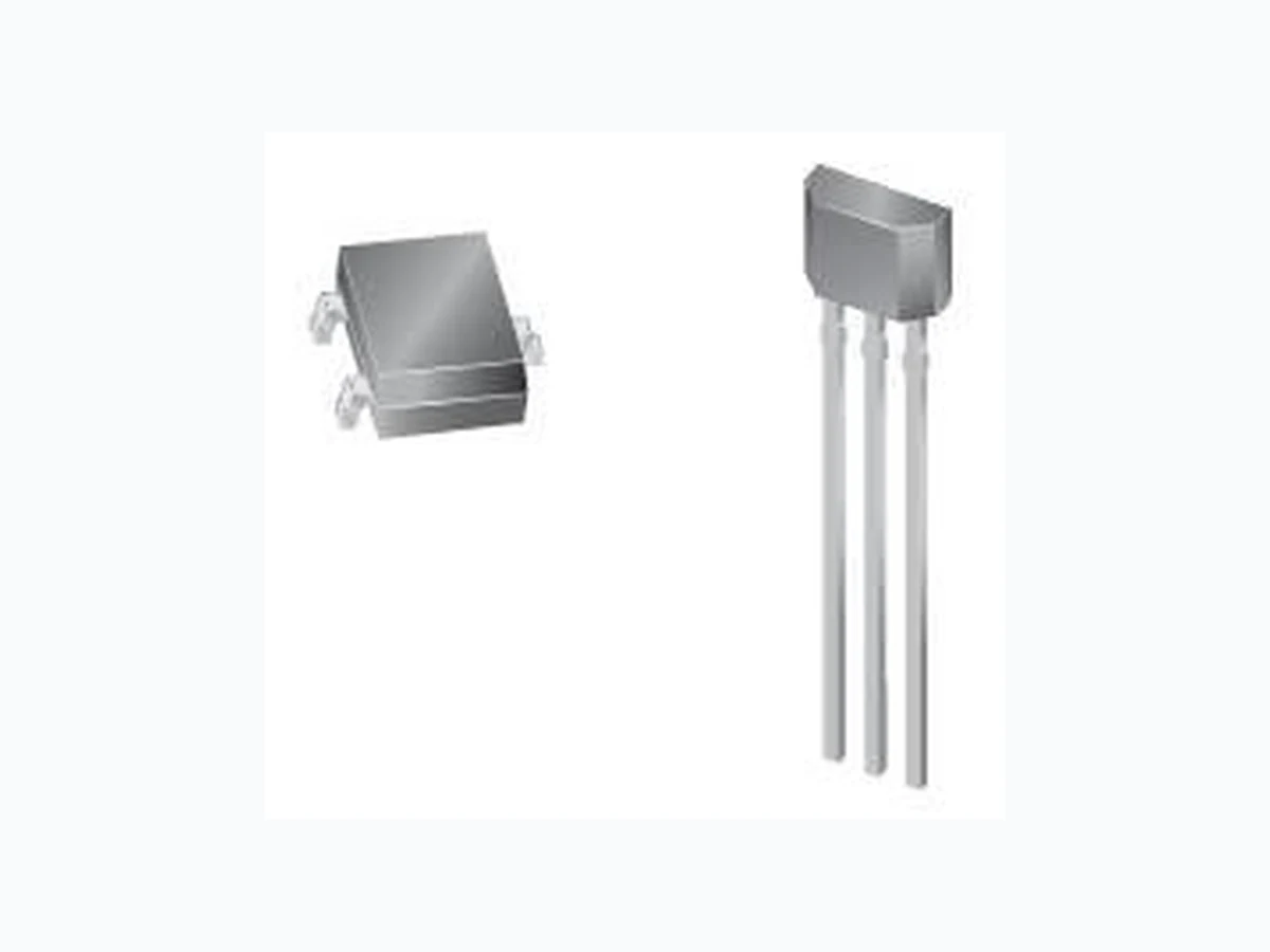
Unipolar Hall Switch-Low Sensitivity 1 V2.00 May 1, 20 12 Features and Benefits – 3.5V to 24V Operation – -40℃ to 150℃ Superior temperature operation – CMOS technology – Low current consumption – Chopper-stabilized amplifier stage – Open drain output – Low sensitivity – Small Size-SOT23 3L or SIP 3L – both RoHS compliant packages VDD OUT Voltage Regulatr Chopper Hall Plate GND Pin 1 – VDD Pin 1 – VDD Pin 2 – GND Pin 2 – OUT Pin 3 – OUT Pin 3 – GND 3 pin SOT23 (suffix SO) 3 pin SIP (suffix UA) Application Examples – Automotive, Consumer and Industrial – Solid-state switch – Brushless DC motor commutation – Speed detection – Angular position detection – Proximity detection – Current detector Functional Block Diagram
Unipolar Hall Switch-Low Sensitivity 2 V2.00 May 1, 20 12 General Descriptions The S5881-AA is a unipolar Hall-effect sensor IC fabricated from CMOS technology. The device integrates a voltage regulator, Hall sensor with dynamic offset cancellation system, small signal amplifier, Schmitt t rigger and an open-drain output driver. With suitable output pull up, they can be used with bipolar or CMOS logic circuits. These Hall-effect switches are monolithic integrated circuits with tighter magnetic specifications, designed to operate continuously over extended temperatures to +150 ℃,and are more stable with both temperature and supply voltage changes. The unipolar switching characteris tic makes these devices ideal for use with a simple bar or rod magnet. Thanks to i ts wide operating voltage range and extended choice of temperature range, it is quite suitable for use in automotive, industrial and consumer applications. The device is delivered in a Small Outline Transistor (SOT) or in a Plastic Single In Line ( SIP 3L flat). Both 3 -lead packages are RoHS compliant. Glossary of Terms MilliTesla (mT), Gauss Units of magnetic flux density: 1mT = 10 Gauss RoHS Restriction of Hazardous Substances Operating Point (BOP) Magnetic flux density applied on the branded side of the package which turns the output driver ON (VOUT = VDSon) Release Point (BRP) Magnetic flux density applied on the branded side of the package which turns the output driver OFF (VOUT = high)
Unipolar Hall Switch-Low Sensitivity 3 V2.00 May 1, 20 12 Pins Definition and Description Absolute Maximum Ratings Parameter Symbol Value Units Supply Voltage VDD 28 V Supply Current IDD 50 mA Output Voltage VOUT 28 V Output Current IOUT 50 mA Storage Temperature Range TS -65 to 170 °C Absolute maximum ratings Operating Temperature Range Symbol Value Units Temperature Suffix “E” TA -40 to 85 °C Temperature Suffix “K” TA -40 to 125 °C Temperature Suffix “L” TA -40 to 150 °C Exceeding the absolute maximum ratings may cause permanent damage. Exposure to absolute-maximum- rated conditions for extended periods may affect device reliability. SOT Pin № SIP Pin № Name Type Function 1 1 VDD Supply Supply Voltage pin 2 3 OUT Output Open Drain Output pin 3 2 GND Ground Ground pin
Unipolar Hall Switch-Low Sensitivity 4 V2.00 May 1, 20 12 General Electrical Specifications DC Operating Parameters TA = 25℃, VDD= 3.5V to 24V (unless otherwise specified) Parameter Symbol Test Conditions Min Typ Max Units Supply Voltage VDD Operating 3.5 24 V Supply Current IDD B < BRP 1.5 2.5 5 mA Output Saturation Voltage VDSon IOUT = 20mA, B > BOP 0.4 0.5 V Output Leakage Current IOFF B < BRP VOUT = 24V 0.01 10 µA Output Rise Time tr RL = 1kΩ, CL = 20pF 0.25 µs Output Fall Time tf RL =1kΩ, CL = 20pF 0.25 µs Magnetic Specifications DC Operating Parameters VDD = 3.5V to 24V (unless otherwise specified) S5881-AA Parameter Symbol Test Conditions Min Typ Max Units Operating Point BOP Ta=25℃,Vdd=12V DC 30 50 70 G Release Point BRP 15 35 50 G Hysteresis BHYS 30 G
Application Information
Typical Three-Wire Application Circuit
Unipolar Hall Switch-Low Sensitivity 5 V2.00 May 1, 20 12 Automotive and Harsh, Noisy Environments Three-Wire Circuit Application Comments For proper operation, a 100nF bypass capacitor should be placed as close as possible to the device between the VDD and ground pin. For reverse voltage protection, it is recommended to connect a resistor or a diode in series with the VDD pin. When using a resistor, three points are important: - The resistor has to limit the reverse current to 50mA maximum (VCC / R1 - The resulting device supply voltage VDD has to be higher than VDD min (VDD = VCC – R1.IDD) - The resistor has to withstand the power dissipated in reverse voltage condition (PD = VCC2/ R1) Using a diode, a reverse current cannot flow and the voltage drop is almost constant (0.7V). Both solutions provide the required reverse voltage protection. When a weak power supply is used or when the device is intended to be used in noisy environment, it is recommended that figure 13.3 from the Application Information section is used. The low-pass filter formed by R1 and C1 and the Zener diode Z1 bypass the disturbances or voltage spikes occurring on the device supply voltage VDD. The diode D1 provides additional reverse voltage protection. ESD Precautions Electronic semiconductor products are sensitive to Electro Static Discharge (ESD). Always observe Electro Static Discharge control procedures whenever handling semiconductor products.
Unipolar Hall Switch-Low Sensitivity 6 V2.00 May 1, 20 12
Package Information
Package UA, 3-Pin SIP:
Unipolar Hall Switch-Low Sensitivity 7 V2.00 May 1, 20 12 Package SE, 3-Pin SOT-23:
Ordering Information
Part No. Pb-free Temperature Code Package Code Packing S5881-AAESOT YES -40°C to 85°C SOT-23 7-in. reel, 3000 pieces/reel S5881-AAEUA YES -40°C to 85°C TO-92 Bulk, 1000 pieces/bag S5881-AAKSOT YES -40°C to 125°C SOT-23 7-in. reel, 3000 pieces/reel S5881-AAKUA YES -40°C to 125°C TO-92 Bulk, 1000 pieces/bag S5881-AALSOT YES -40°C to 150°C SOT-23 7-in. reel, 3000 pieces/reel S5881-AALUA YES -40°C to 150°C TO-92 Bulk, 1000 pieces/bag