

 Download PDF
SXH-001T-P0.6N JST
Document overview
- PDF pages: 9
Technical content
Page 1
XH CONNECTOR
Emboss Tape
Radial Tape
Disconnectable Crimp style connectors
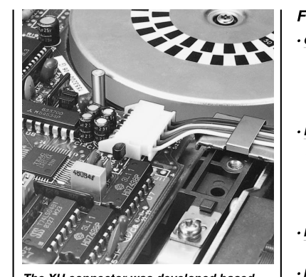
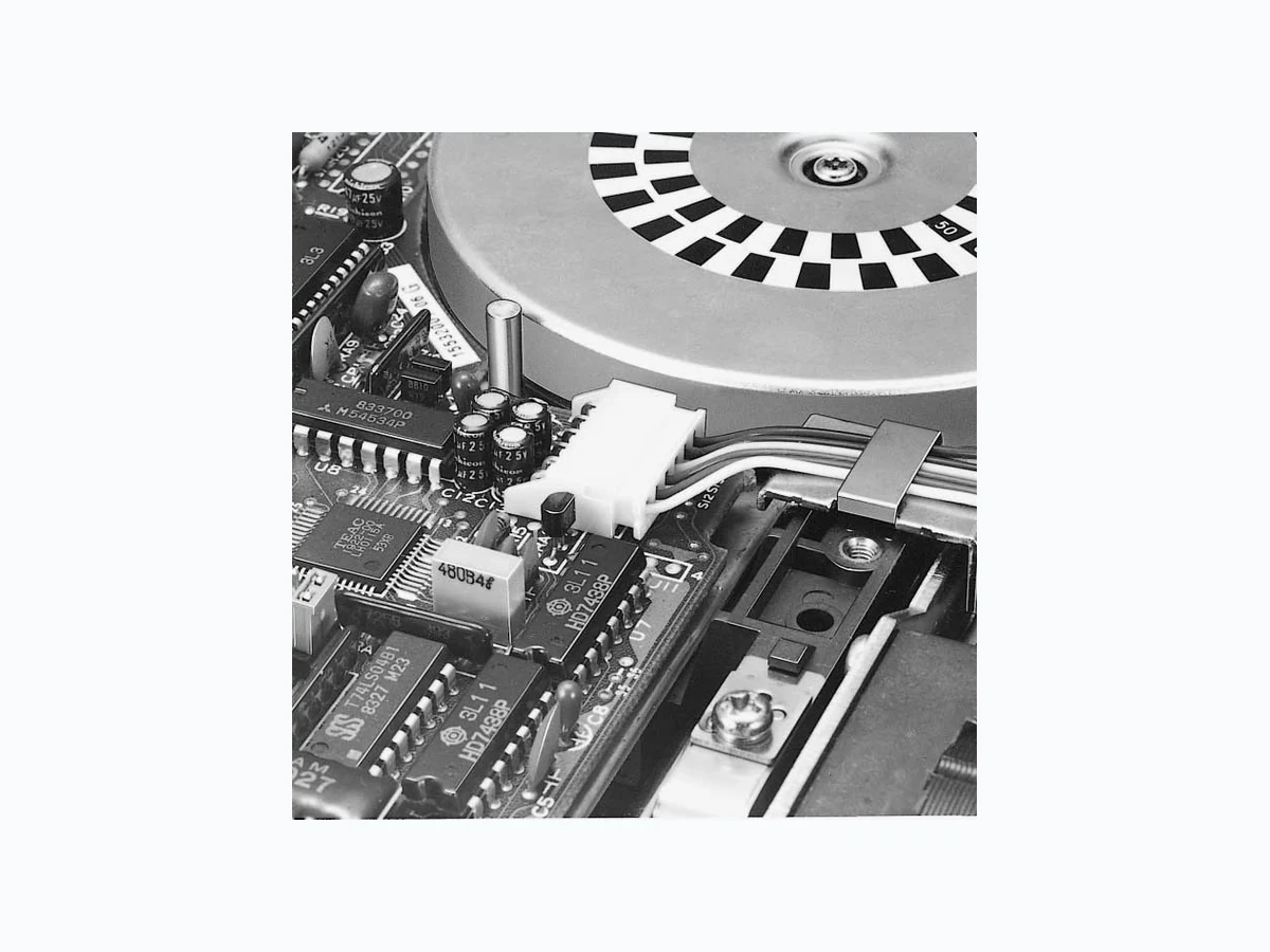
The XH connector was developed based
on the high reliability and versatility of our
NH series connectors. The connector is
very small with a mounting height of
9.8mm (.386"). Yet it meets the needs for
high-density mounting and miniaturization
of electronic equipment, including VCRs,
radio-cassette players, and car stereo
systems.
Features ––––––––––––––––––––––––
- Original folded beam contact The protected, folded beam contact in this connector provides high contact pressure with an over-stress stop feature. This ensures dependable continuity when used with low voltage, low current carrying circuits (dry circuits). The wire crimp section is mechanically decoupled from the post insertion section which, in turn, prevents the mating area from being adversely affected by crimping.
- Box-shaped shrouded header The four-sided, box-shaped shroud prevents the receptacle from being misinserted or pried during insertion and removal. The shroud also prevents foreign matter from reaching the posts and resists contact deformation due to handling and shipping. Furthermore, a serrated, oversized square post is pressure-fit into each square hole to completely protect the post against heat and to prevent flux from entering during dip soldering.
- Header with a boss This header has a boss (projection) on the bottom of the housing to prevent improper insertion in printed circuit boards.
- Interchangeability This header is interchangeable with those of 2.5mm (.098") pitch insulation displacement NR and NRD connectors and board-to-board JQ connectors.
- Conforming to the HA terminal The 4-circuit XH connector conforms to the HA terminal specified in JEM 1427 (Japanese Electric Machine Industry Association Standards).
Specifications –––––––––––––––––––
- Current rating: 3A AC, DC (AWG#22)
- Voltage rating: 250V AC, DC
- Temperature range: -25˚C to +85˚C
(including temperature rise in applying electrical current)
- Contact resistance: Initial value/10m Ω max.
After environmental testing/20m Ω max.
- Insulation resistance: 1,000M Ω min.
- Withstanding voltage: 1,000V AC/minute
- Applicable wire: AWG #30 to #22
- Applicable PC board thickness: 1.6mm(.063") \* Contact JST if Lead-Free product is required. \* Refer to "General Instruction and Notice when using Terminals and Connectors" at the end of this catalog.
\* Contact JST for details.
Standards–––––––––––––––––––––––
0 Recognized E60389
1Certified LR20812
2J50014297
Page 2
XH CONNECTOR
Contact –––––––––––––––––––––––––––––––––––––––––––––––––––––––––––––––––
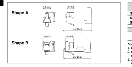
| Model No. SXH-001T-P0.6N | Shape A | Applicable Wire | Q'ty / reel 5,000 | ||
| mm2 0.13 to 0.33 | AWG# 26 to 22 | Insulation O.D mm(in.) 1.3 to 1.9(.051 to .075) | |||
| SXH-001T-P0.6 | B | 0.08 to 0.33 | 28 to 22 | 1.2 to 1.9(.047 to .075) | 8,000 |
| SXH-002T-P0.6 | 0.05 to 0.13 | 30 to 26 | 0.9 to 1.3(.035 to .051) | ||
Material and Finish
Phosphor bronze, tin-plated
Note:
1. Contact JST if you require gold-plated contacts or contacts made of brass.
2. Contact JST also if you require shielded wires, thin wires or other
special wires.
3. SXH-001T-P0.6N is low-insertion force type contact, for easier insertion/
withdrawal, which would be less resistant to the vibration.
Housing –––––––––––––––––––––––––––––––––––––––––––––––––––––––––––––––––
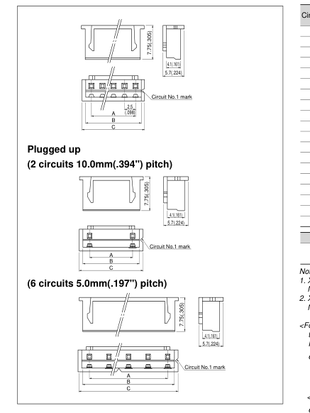
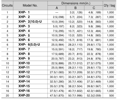
Material
Nylon 6, UL94V-0, natural (white)
Note:
1. XHP-2(10.0)-U is 2 circuits 10.0mm(.394") pitch plugged up.
Not UL/CSA/TU¨ V approved.
2. XHP-6(5.0)-U is 6 circuits 5.0mm(.197") pitch plugged up.
Not UL/CSA/TU¨ V approved.
<For reference>
As the color identification,
the following alphabet shall be put in the underlined part.
For availability, delivery and minimum order quantity, contact JST.
ex. XHP-1-oo-
(blank)…natural (white) BK…black R…red E…blue Y…yellow L…lemon yellow M…green D…orange N…brown FY…vivid yellow
<Plugged up type>
ex. XHP-2(10.0)-U-oo-
(blank)…natural (white) R…red E…blue
Page 3
XH CONNECTOR
Through-hole type shrouded header –––––––––––––––––––––––––––––––––––––––––
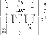
The shrouded headers are interchangeable with those of the BR, NR and NRD insulation displacement connectors, and JQ board-to-board connectors.
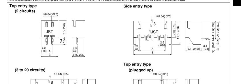
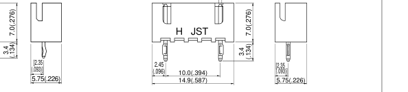
B
| Circuits | Model No. | Dimensions mm(in.) | Q'ty / box | ||||
| Top entry type | Side entry type | A | B | Top entry type | Side entry type | ||
| 2 | B 2B-XH-A | – | S 2B-XH-A | 2.5( .098) | 7.4( .291) | 1,000 | 1,000 |
| 2 | B2 (10.0)B-XH-A- | U – | – | 10.0( .394) | 14.9( .587) | 1,000 | 1,000 |
| 3 | B 3B-XH-A | S 3B-XH-A-1 | S 3B-XH-A | 5.0( .197) | 9.9( .390) | 1,000 | 1,000 |
| 4 | B 4B-XH-A | S 4B-XH-A-1 | S 4B-XH-A | 7.5( .295) | 12.4( .488) | 500 | 500 |
| 5 | B 5B-XH-A | S 5B-XH-A-1 | S 5B-XH-A | 10.0( .394) | 14.9( .587) | 500 | 500 |
| 6 | B 6B-XH-A | S 6B-XH-A-1 | S 6B-XH-A | 12.5( .492) | 17.4( .685) | 500 | 500 |
| 7 | B 7B-XH-A | S 7B-XH-A-1 | S 7B-XH-A | 15.0( .591) | 19.9( .783) | 500 | 250 |
| 8 | B 8B-XH-A | S 8B-XH-A-1 | S 8B-XH-A | 17.5( .689) | 22.4( .882) | 500 | 250 |
| 9 | B 9B-XH-A | S 9B-XH-A-1 | S 9B-XH-A | 20.0( .787) | 24.9( .980) | 500 | 250 |
| 10 | B10B-XH-A | S10B-XH-A-1 | S10B-XH-A | 22.5( .886) | 27.4(1.079) | 250 | 250 |
| 11 | B11B-XH-A | S11B-XH-A-1 | S11B-XH-A | 25.0( .984) | 29.9(1.177) | 250 | 250 |
| 12 | B12B-XH-A | S12B-XH-A-1 | S12B-XH-A | 27.5(1.083) | 32.4(1.276) | 250 | 200 |
| 13 | B13B-XH-A | S13B-XH-A-1 | S13B-XH-A | 30.0(1.181) | 34.9(1.374) | 250 | 200 |
| 14 | B14B-XH-A | S14B-XH-A-1 | S14B-XH-A | 32.5(1.280) | 37.4(1.472) | 250 | 200 |
| 15 | B15B-XH-A | S15B-XH-A-1 | S15B-XH-A | 35.0(1.378) | 39.9(1.571) | 250 | 100 |
| 16 | B16B-XH-A | – | S16B-XH-A | 37.5(1.476) | 42.4(1.669) | 200 | 100 |
| 20 | B20B-XH-A | – | – | 47.5(1.870) | 52.4(2.063) | 100 | – |
| Material and Finish | |||||||
| Post: Brass, copper-undercoated, tin/lead-plated Wafer: Nylon 66, UL94V-0, natural (white) | |||||||
Note: B2(10.0)B-XH-A-U is 2 circuits 10.0mm(.394") pitch plugged up. Not UL/CSA/TU¨ V approved.
<For reference> As the color identification, the following alphabet shall be put in the underlined part. For availability, delivery and minimum order quantity, contact JST. ex. S3B-XH-A(-1)-oo- (blank)…natural (white) BK…black R…red E…blue Y…yellow L…lemon yellow M…green D…orange N…brown FY…vivid yellow
Page 4
XH CONNECTOR
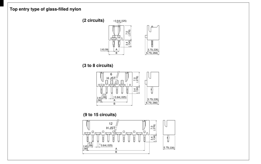
Through-hole type shrounded header ––––––––––––––––––––––––––––––––––––––––
| Circuits | Model No. | Dimensions mm(in.) | Q'ty / box | |
| A | B | |||
| 2 | B 2B-XH-2 | 2.5( .098) | 7.4( .291) | 1,000 |
| 3 | B 3B-XH-2 | 5.0( .197) | 9.9( .390) | 1,000 |
| 4 | B 4B-XH-2 | 7.5( .295) | 12.4( .488) | 500 |
| 5 | B 5B-XH-2 | 10.0( .394) | 14.9( .587) | 500 |
| 6 | B 6B-XH-2 | 12.5( .492) | 17.4( .685) | 500 |
| 7 | B 7B-XH-2 | 15.0( .591) | 19.9( .783) | 500 |
| 8 | B 8B-XH-2 | 17.5( .689) | 22.4( .882) | 250 |
| 9 | B 9B-XH-2 | 20.0( .787) | 24.9( .980) | 250 |
| 10 | B10B-XH-2 | 22.5( .886) | 27.4(1.079) | 250 |
| 11 | B11B-XH-2 | 25.0( .984) | 29.9(1.177) | 250 |
| 12 | B12B-XH-2 | 27.5(1.083) | 32.4(1.276) | 250 |
| 13 | B13B-XH-2 | 30.0(1.181) | 34.9(1.374) | 250 |
| 14 | B14B-XH-2 | 32.5(1.280) | 37.4(1.472) | 250 |
| 15 | B15B-XH-2 | 35.0(1.378) | 39.9(1.571) | 250 |
| Material and Finish | ||||
| Post: Brass, copper-undercoated, tin/lead-plated Wafer: Glass-filled nylon 66, UL94V-0, natural (ivory) | ||||
<For reference> As the color identification,
the following alphabet shall be put in the underlined part.
For availability, delivery and minimum order quantity, contact JST.
ex. B2B-XH-2-oo-
(blank)…natural (ivory) C…black R…red E…blue Y…yellow M…green
Page 5
XH CONNECTOR
Through-hole type shrouded header –––––––––––––––––––––––––––––––––––––––––
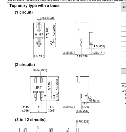
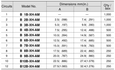
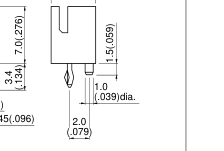
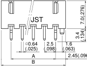
The shrouded headers are interchangeable with those of the NR, NRD and BR insulation displacement connectors, and JQ board-to-board connectors.
Material and Finish
Post: Brass, copper-undercoated, tin/lead-plated Wafer: Nylon 66, UL94V-0, natural (white)
Note: B1B-XH-AM is not UL/CSA/TU¨ V approved. <For reference> As the color identification, the following alphabet shall be put in the underlined part. For availability, delivery and minimum order quantity, contact JST. ex. B1B-XH-AM-oo- (blank)…natural (white) BK…black R…red E…blue Y…yellow L…lemon yellow M…green
Page 6
XH CONNECTOR
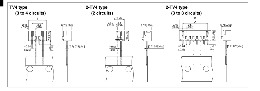
Through-hole type shrouded header on radial-tape –––––––––––––––––––––––––––––
| Circuits | Model No. | Dimensions mm(in.) | Q'ty / box | ||
| A | B | A | B | ||
| 2 | – | B2B-XH-2-TV4 | – | – | 1,000 |
| 3 | B3B-XH-TV4 | B3B-XH-2-TV4 | 5.0(.197) | 9.9(.390 | ) 1,000 |
| 4 | B4B-XH-TV4 | B4B-XH-2-TV4 | 7.5(.295) | 12.4(.488 | ) 500 |
| 5 | – | B5B-XH-2-TV4 | 10.0(.394) | 14.9(.587 | ) 500 |
| 6 | – | B6B-XH-2-TV4 | 12.5(.492) | 17.4(.685 | ) 500 |
| 7 | – | B7B-XH-2-TV4 | 15.0(.591) | 19.9(.783 | ) 500 |
| 8 | – | B8B-XH-2-TV4 | 17.5(.689) | 22.4(.882 | ) 500 |
Material and Finish Post: Copper alloy, copper-undercoated, tin/lead-plated Wafer: TV4 type/ Nylon 66, UL94V-0 2-TV4 type/ Glass-filled nylon 66, UL94V-0
<For reference> As the color identification, the following alphabet shall be put in the underlined part. For availability, delivery and minimum order quantity, contact JST. ex. B2B-XH-2-TV4-oo- (blank)…natural (ivory) C…black (glass-filled) BK…black R…red E…blue Y…yellow M…green
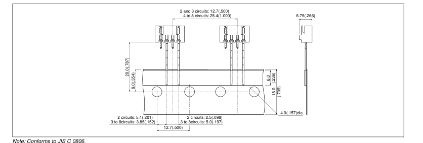
Taping specification of through-hole type shrouded header ––––––––––––––––––––––
Page 7
XH CONNECTOR
Packaging specifications of through-hole type shrouded header––––––––––––––––––
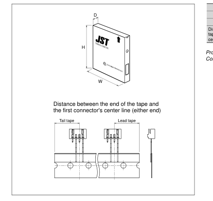
| Package typ | e Flat pack (zig zag folded) |
|---|---|
| Distance betwee | n folds 24 indexing holes perfold (304.8mm/12") |
| Box size | (316x45x330mm)12.4"(W)x1.8"(D)x13.0"(H) |
| Distance between the tape and the first conn center line (either end) | end of the ector's 19.05mm(.750") |
Products of different packaging specifications are also available. Contact JST for details.
Through-hole type PC board layout (viewed from soldering side) and Assembly layout –––
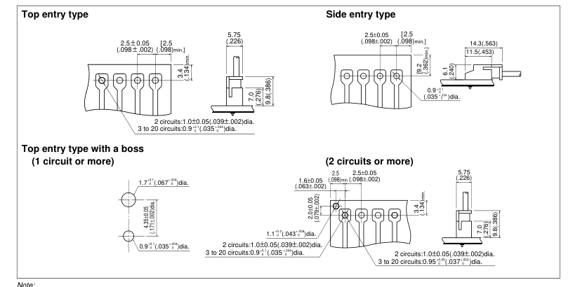
- Tolerances are non-cumulative: ±0.05mm(±.002" ) for all centers. 2. Hole dimensions differ according to the kind of PC board and piercing method. If printed circuit boards made of hard material are used, the hole dimensions should be larger. The dimensions above should serve as a guideline. Contact JST for details.
Page 8
XH CONNECTOR
SMT type shrouded header –––––––––––––––––––––––––––––––––––––––––––––––––
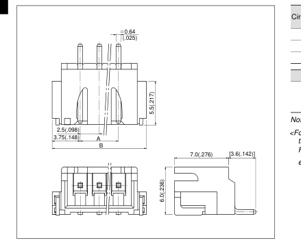
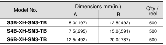
Circuits
3 4 6
Material and Finish
Pin: Copper alloy, copper-undercoated, tin/lead-plated Wafer: Nylon 46, UL94V-0, natural (white) Solder tab: Brass, copper-undercoated, tin/lead-plated
Note: The products listed above are supplied on embossed-tape.
<For reference>
As the color identification,
the following alphabet shall be put in the underlined part.
For availability, delivery and minimum order quantity, contact JST.
ex. S3B-XH-SM3-oo-TB-
(blank)…natural (white) M…green R…red E…blue L…lemon yellow
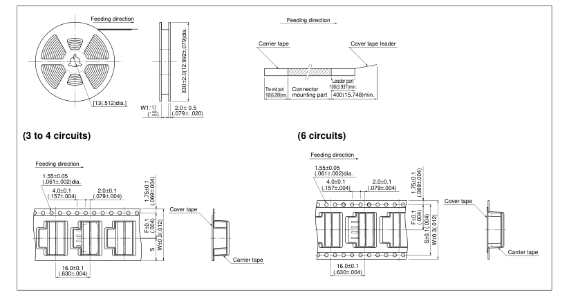
Taping specifications of SMT type shrouded header ––––––––––––––––––––––––––––
Note:
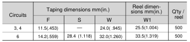
1. Specifications conform to JIS C 0806. The tape width, connector recess
dimensions, etc. are determined by the number of circuits and external shape
of the connector to be loaded.
2. Specifications are subject to change without prior notice.
Page 9
XH CONNECTOR
SMT type PC board layout (viewed from component side) ––––––––––––––––––––––––––––
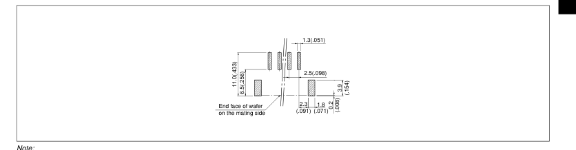
1. Tolerances are non-cumulative: ±0.05mm(±.002" ) for all centers.
2. The dimensions above should serve as a guideline. Contact JST for details.
Applicator for the semi-automatic press AP-K2N –––––––––––––––––––––––––––––––
| Contact | Crimp applicator MKS-L | Compact crimp applicator MKS-LS | Strip-crimp applicator MKS-SC | ||
| with safety cover | without safety cover | with safety cover | without safety cover | with safety cover | |
| SXH-001T-P0.6N | APLMK SXH001-06N | APLNC SXH001-06N | APLMKLS SXH001-06N | APLLSNC SXH001-06N | APLSC SXH001-06N |
| SXH-001T-P0.6 | APLMK SXH001-06 | APLNC SXH001-06 | APLMKLS SXH001-06 | APLLSNC SXH001-06 | APLSC SXH001-06 |
| SXH-002T-P0.6 | APLMK SXH002-06 | APLNC SXH002-06 | APLMKLS SXH002-06 | APLLSNC SXH002-06 | APLSC SXH002-06 |