

 Download PDF
S3901-1024Q_07 HAMAMATSU
Document overview
- PDF pages: 4
Technical content
Page 1
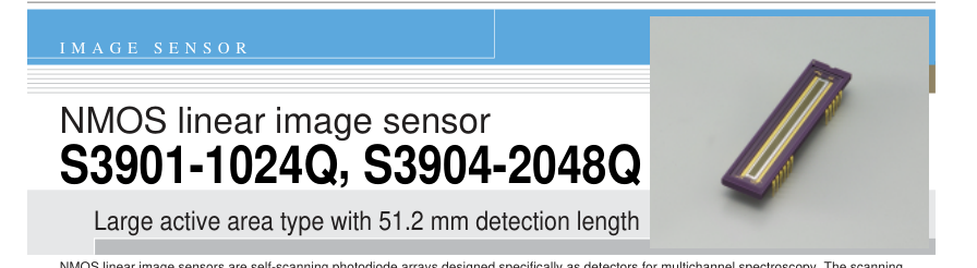
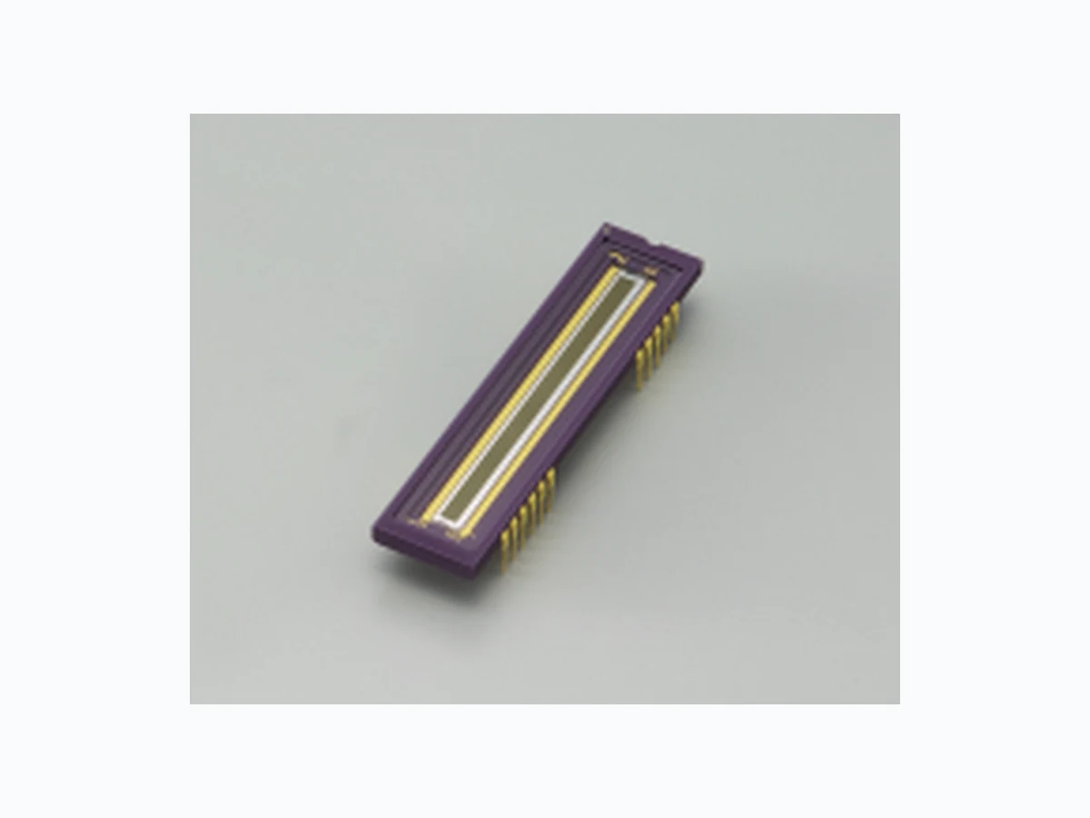
NMOS linear image sensors are self-scanning photodiode arrays designed specifically as detectors for multichannel spectroscopy. The scanning circuit is made up of N-channel MOS transistors, operates at low power consumption and is easy to handle. Each photodiode has a large active area, high UV sensitivity yet very low noise, delivering a high S/N even at low light levels. The current output type NMOS linear image sensors also feature excellent output linearity and wide dynamic range. S3901-1024Q uses photodiodes with a height of 2.5 mm, arrayed at a spacing of 50 µm. S3904-2048Q has photodiodes with a height of 2.5 mm, arrayed at a spacing of 25 µm. The photodiode arrays are available in 2 different
pixel quantities, 1024 (S3901-1024Q) and 2048 (S3904-2048Q). Quartz glass is the standard window material.

Pixel height: 2.5 mm Active area length: 51.2 mm l High UV sensitivity with good stability l Low dark current and large saturation charge allow long integration time and a wide dynamic range at room temperature l Excellent output linearity and sensitivity spatial uniformity l Low power consumption: 1 mW Max. l Start pulse and clock pulses are CMOS logic compatible
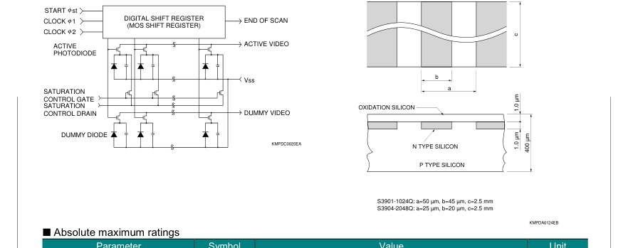
Figure 1 Equivalent circuit
Figure 2 Active area structure
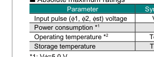
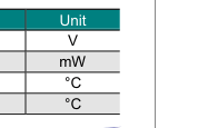
| Symbol | Value |
|---|---|
| Vφ | 15 |
| P | 1 |
| Topr | -40 to +65 |
| Tstg | -40 to +85 |
\*1: Vφ=5.0 V \*2: No condensation
Page 2

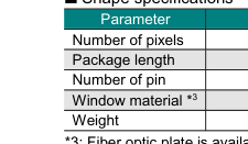
| S3901-1024Q | S3904-2048Q |
| 1024 | 2048 |
| 65.0 | |
| 22 | |
| Quartz | |
| 8.5 | |
Unit - mm - - g
\*3: Fiber optic plate is available.
I Specifications (Ta=25 °C)
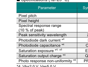
| Symbol | S3901-1024Q | S3904-2048Q | ||||
|---|---|---|---|---|---|---|
| Min. | Typ. | Max. | Min. | Typ. | Max. | |
| - | - | 50 | - | - | 25 | - |
| - | - | 2.5 | - | - | 2.5 | - |
| λ | 200 to 1000 | 200 to 1000 | ||||
| λp | - | 600 | - | - | 600 | - |
| ID | - | 0.2 | 0.6 | - | 0.1 | 0.3 |
| Cph | - | 20 | - | - | 10 | - |
| Esat | - | 180 | - | - | 180 | - |
| Qsat | - | 50 | - | - | 25 | - |
| PRNU | - | - | ±3 | - | - | ±3 |
Unit
µm mm
nm
nm pA pF mlx · s pC %

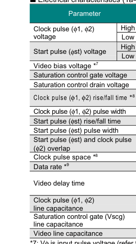
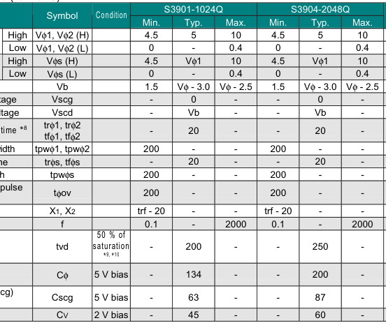
Unit
V V V V V V V
ns
ns ns ns
ns
ns kHz
ns
pF
pF
pF

Page 3
Figure 3 Dimensional outline (unit: mm)
ACTIVE AREA 51.2 × 2.5
25.6 ± 0.5
65.0
PHOTOSENSITIVE SURFACE
0.46
0.25
25.4
2.54
48.26
15.24
\* Optical distance from the outer surface of the quartz window to the chip surface
Figure 4 Pin connection
2 22 1
NC
1 21 2
NC
st
20 3
NC
Vss
19 4
NC
Vscg
18 5
NC
NC
17 6
NC
Vscd
16 7
NC
Vss
15 8
NC
ACTIVE VIDEO
14 9
NC
DUMMY VIDEO
13 10
NC
Vsub
12 11
END OF SCAN
Vss, Vsub and NC should be grounded.
KMPDC0109EA
Terminal
Input or output
Input
φ1, φ2
(CMOS logic compatible)
Input
φst
(CMOS logic compatible)
Vss
-
Vscg
Input
Vscd
Input
Active video
Output
Dummy video
Output
Vsub
-
Output
End of scan
(CMOS logic compatible)
NC
-
KMPDA0123EA
Description
Pulses for operating the MOS shift register. The video data rate is equal to the clock pulse frequency since the video output signal is obtained synchronously with the rise of φ2 pulse. Pulse for starting the MOS shift register operation. The time interval between start pulses is equal to the signal accumulation time. Connected to the anode of each photodiode. This should be grounded. Used for restricting blooming. This should be grounded. Used for restricting blooming. This should be biased at a voltage equal to the video bias voltage. Video output signal. Connects to photodiode cathodes when the address is on. A positive voltage should be applied to the video
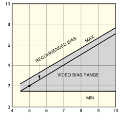
line in order to use photodiodes with a reverse voltage. When the amplitude of φ1 and φ2 is 5 V, a video bias voltage of 2 V is recommended. This has the same structure as the active video, but is not connected to photodiodes, so only spike noise is output. This should be biased at a voltage equal to the active video or left as an open-circuit when not needed. Connected to the silicon substrate. This should be grounded. This should be pulled up at 5 V by using a 10 kΩ resistor. This is a negative going pulse that appears synchronously with the φ2 timing right after the last photodiode is addressed. Should be grounded.
Page 4
Figure 5 Spectral response (typical example)
(Ta=25 ˚C)
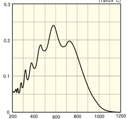
WAVELENGTH (nm)
KMPDB0149EA
Figure 7 Timing chart
Figure 6 Output charge vs. exposure
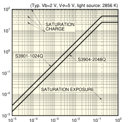
EXPOSURE (lx · s)
KMPDB0160EB
Figure 8 Video bias voltage margin
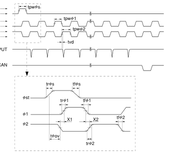
V s (H) st V s (L) V 1 (H) 1 V 1 (L) V 2 (H) 2 V 2 (L)
ACTIVE VIDEO OUTPUT
END OF SCAN
CLOCK PULSE AMPLITUDE (V)
KMPDB0043EA
KMPDC0022EA
Information furnished by HAMAMATSU is believed to be reliable. However, no responsibility is assumed for possible inaccuracies or omissions. Specifications are subject to change without notice. No patent rights are granted to any of the circuits described herein. ©2007 Hamamatsu Photonics K.K.
HAMAMATSU PHOTONICS K.K., Solid State Division
1126-1 Ichino-cho, Higashi-ku, Hamamatsu City, 435-8558 Japan, Telephone: (81) 53-434-3311, Fax: (81) 53-434-5184, www.hamamatsu.com U.S.A.: Hamamatsu Corporation: 360 Foothill Road, P.O.Box 6910, Bridgewater, N.J. 08807-0910, U.S.A., Telephone: (1) 908-231-0960, Fax: (1) 908-231-1218 Germany: Hamamatsu Photonics Deutschland GmbH: Arzbergerstr. 10, D-82211 Herrsching am Ammersee, Germany, Telephone: (49) 08152-3750, Fax: (49) 08152-2658 France: Hamamatsu Photonics France S.A.R.L.: 19, Rue du Saule Trapu, Parc du Moulin de Massy, 91882 Massy Cedex, France, Telephone: 33-(1) 69 53 71 00, Fax: 33-(1) 69 53 71 10 United Kingdom: Hamamatsu Photonics UK Limited: 2 Howard Court, 10 Tewin Road, Welwyn Garden City, Hertfordshire AL7 1BW, United Kingdom, Telephone: (44) 1707-294888, Fax: (44) 1707-325777
North Europe: Hamamatsu Photonics Norden AB: Smidesvägen 12, SE-171 41 Solna, Sweden, Telephone: (46) 8-509-031-00, Fax: (46) 8-509-031-01 Italy: Hamamatsu Photonics Italia S.R.L.: Strada della Moia, 1/E, 20020 Arese, (Milano), Italy, Telephone: (39) 02-935-81-733, Fax: (39) 02-935-81-741