
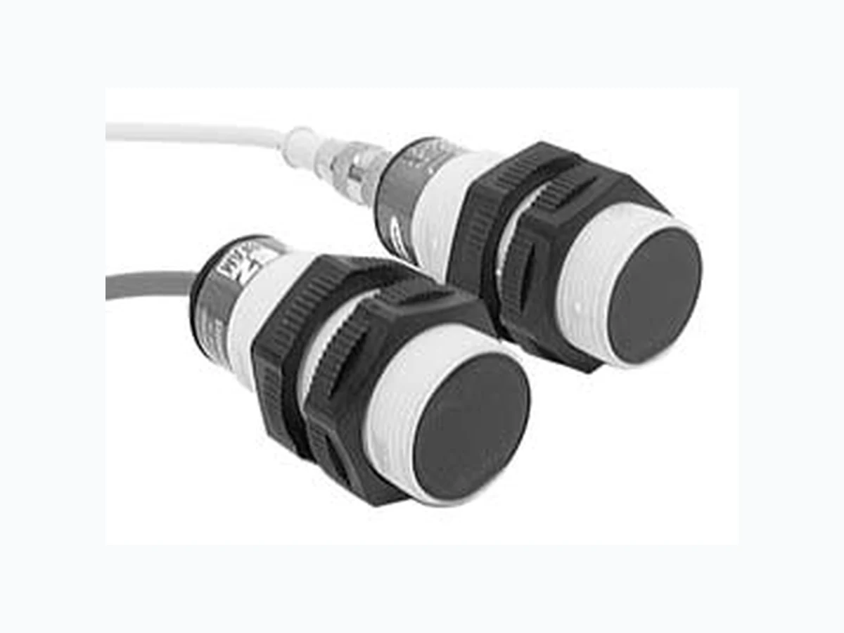
S30 ETC2
Document overview
- Manufacturer or author: Provided By www.digicamel.com(FREE DATASHEET DOWNLOAD SITE)
- PDF pages: 7
Technical content
Features
- Featuring EZ-BEAM® technology, the specially designed optics and electronics provide reliable sensing without the need for adjustments
- 30 mm plastic threaded barrel sensor in opposed, retroreflective or fixed-field modes
- Completely epoxy-encapsulated to provide superior durability, even in harsh sensing environments rated to IP69K
- Innovative dual-indicator system takes the guesswork out of sensor performance monitoring
- 20 to 250V ac (3-wire hookup); SPST solid-state switch output, maximum load 300 mA Models
2 P/N 121519
Banner Engineering Corp. • Minneapolis, MN U.S.A. the sensor ignores the object. conditions (see Background Reflectivity and Placement). illustrated in Figures 5 and 6. maximum excess gain. The excess gain curves for these products are shown on page 5. two guidelines will improve sensing reliability. beyond the cutoff distance as possible. triggering. A better solution, if possible, may be to reposition the object or the sensor. is parallel to the sensing axis. Figure 2. Fixed-field sensing axis Figure 1. Fixed-field concept
S30 Sensors – ac-Voltage Series
4 P/N 121519
Banner Engineering Corp. • Minneapolis, MN U.S.A. www.bannerengineering.com • Tel: 763.544.3164 Supply Voltage and Current 20 to 250V ac (50/60 Hz) Average current: 20 mA Peak current: 200 mA @ 20V ac, 500 mA @ 120V ac, 750 mA @ 250V ac Supply Protection Circuitry Protected against transient voltages Output Configuration SPST solid-state ac switch; three-wire hookup; light operate or dark operate, depending on model Light Operate: Output conducts when sensor sees its own (or the emitter’s) modulated light Dark Operate: Output conducts when the sensor sees dark Output Rating 300 mA maximum (continuous) Fixed-Field models: derate 5 mA/°C above +50° C (+122° F) Inrush capability: 1 amp for 20 milliseconds, non-repetitive OFF-state leakage current: < 100 microamps ON-state saturation voltage: 3V @ 300 mA ac; 2V @ 15 mA ac Output Protection Circuitry Protected against false pulse on power-up Output Response Time Opposed mode: 16 milliseconds ON, 8 milliseconds OFF Other models: 16 milliseconds ON and OFF NOTE: 100 millisecond delay on power-up; outputs do not conduct during this time. Repeatability Opposed mode: 2 milliseconds Other models: 4 milliseconds Repeatability and response are independent of signal strength Indicators Two LEDs (Green and Yellow) Green ON steady: power to sensor is ON Yellow ON steady: sensor sees light Yellow flashing: excess gain marginal (1 to 1.5x) in light condition Construction PBT polyester housing; polycarbonate (opposed-mode) or acrylic lens Environmental Rating Leakproof design rated NEMA 6P , DIN 40050 (IP69K) Connections 2 m (6.5') attached cable or 4-pin Micro-style quick-disconnect fitting Operating Conditions Temperature: -40° to +70° C (-40° to +158° F) Maximum relative humidity: 90% at 50° C (non-condensing) Vibration and Mechanical Shock All models meet Mil. Std. 202F requirements. Method 201A (Vibration; frequency 10 to 60 Hz, max., double amplitude 0.06" acceleration 10G). Method 213B conditions H&I (Shock: 75G with unit operating; 100G for non-operation) Certifications Specifications
S30 Sensors – ac-Voltage Series Banner Engineering Corp. • Minneapolis, MN U.S.A. www.bannerengineering.com • Tel: 763.544.3164 Excess Gain Performance based on use of a 90% reflectance white test card. † Fixed-Field – 200 mm Ø 16 mm spot size @ 35 mm focus Ø 20 mm spot size @ 200 mm cutoff † Using 18% gray test card: cutoff distance will be 95% of value shown. † Using 6% black test card: cutoff distance will be 90% of value shown. Fixed-Field – 400 mm Ø 17 mm spot size @ 35 mm focus Ø 25 mm spot size @ 400 mm cutoff † Using 18% gray test card: cutoff distance will be 90% of value shown. † Using 6% black test card: cutoff distance will be 85% of value shown. Fixed-Field – 600 mm Ø 17 mm spot size @ 35 mm focus Ø 30 mm spot size @ 600 mm cutoff † Using 18% gray test card: cutoff distance will be 85% of value shown. † Using 6% black test card: cutoff distance will be 75% of value shown. Performance Curves Excess Gain Beam Pattern OpposedPolarized Retro†† Focus and spot sizes are typical. 75 m (250') 60 m (200') 45 m (150') 30 m (100') 15 m (50') 250 mm 500 mm 750 mm 250 mm 500 mm 750 mm 10" 20" 30" 10" 20" 30" DISTANCE S30 Series Opposed Mode 7.5 m (25') 6.0 m (20') 4.5 m (15') 3.0 m (10') 1.5 m (5') 50 mm 100 mm 150 mm 50 mm 100 mm 150 mm DISTANCE S30 Series Polarized Retro with BRT-3 Reflector 100 1 m (3.3') 10 m (33') 100 m (330') 0.1 m (0.33') 1000 E X C E S S G A I N DISTANCE S30 Series Opposed Mode 100 0.1 m (0.33') 1 m (3.3') 10 m (33') 0.01 m (0.033') 1000 E X C E S S G A I N DISTANCE S30 Series Polarized Retro with BRT-3 Reflector 100 10 mm (0.4") 100 mm (4") 1000 mm (40") 1 mm (0.04") E X C E S S G A I N DISTANCE 1000 S30 Series Fixed-field mode with 200 mm far limit cutoff 100 10 mm (0.4") 100 mm 4") 1000 mm 40") 1 mm (0.04") E X C E S S G A I N DISTANCE 1000 S30 Series Fixed-field mode with 400 mm far limit cutoff 100 10 mm (0.4") 100 mm (4") 1000 mm (40") 1 mm (0.04") E X C E S S G A I N DISTANCE 1000 S30 Series Fixed-field mode with 600 mm far limit cutoff †† Performance based on use of a model BRT-3 retroreflector (3" diameter). Actual sensing range may be more or less than specified, depending on the efficiency and reflective area of the retroreflector used.
S30 Sensors – ac-Voltage Series
6 P/N 121519
Banner Engineering Corp. • Minneapolis, MN U.S.A. www.bannerengineering.com • Tel: 763.544.3164 89.4 mm (3.52") 65.0 mm (2.56") Cabled Models QD Models Dimensions bn bu bk 20-250V ac Load Cabled Emitters 20-250V ac No connection rd/wh rd/bk rd gn bn bu 20-250V ac All Other Cabled Models QD Emitters (4-pin Micro-Style) All Other QD Models (4-pin Micro-Style) 20-250V ac No Connection Load rd/wh rd rd/bk gn Hookups
S30 Sensors – ac-Voltage Series P/N 121519 WARRANTY: Banner Engineering Corp. warrants its products to be free from defects for one year. Banner Engineering Corp. will repair or replace, free of charge, any product of its manufacture found to be defective at the time it is returned to the factory during the warranty period. This warranty does not cover damage or liability for the improper application of Banner products. This warranty is in lieu of any other warranty either expressed or implied. Style Model Length Dimensions Pinout 4-pin Micro-style Straight MQAC-406 MQAC-415 MQAC-430 2 m (6.5') 5 m (15') 9 m (30') 4-pin Micro-style Right-angle MQAC-406RA MQAC-415RA MQAC-430RA 2 m (6.5') 5 m (15') 9 m (30') Quick-Disconnect (QD) Cables ø 1/2-20UNF-2B ø15 mm (0.6") 44 mm max. (1.7") 38 mm max. (1.5") 1/2-20UNF-2B ø 15 mm (0.6") 38 mm max. (1.5") Green Wire Red/Black WireRed/White Wire Red Wire