
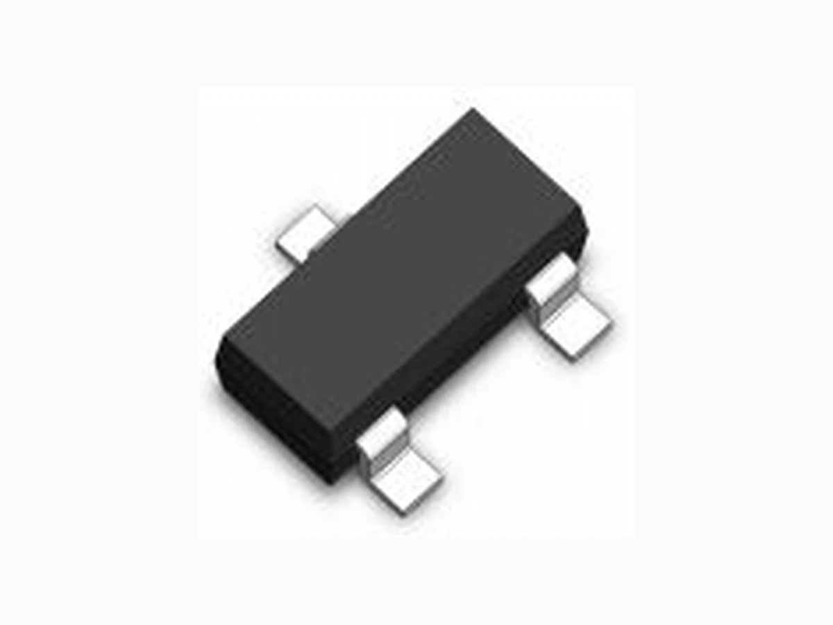
S2N7002ET7G LEIDITECH
Document overview
- Manufacturer or author: Provided By www.digicamel.com(FREE DATASHEET DOWNLOAD SITE)
- PDF pages: 5
Technical content
60V N-Channel Enhancement Mode MOSFET
Description
Package Marking and Ordering Information Device Marking Device Device Package Reel Size Tape width Quantity 72KC SOT-23 Ø180mm 8 mm 3000 units Dimensions SOT-23 Pin Configuration Rev : 01.08.2021 1/ www.leiditech.com Absolute Maximum Ratings (TC=25℃unless otherwise noted)
- Trench Power MV MOSFET technology
- Voltage controlled small signal switch
- Low input Capacitance
- Fast Switching Speed
- Low Input / Output Leakage
- VDS 60V
- ID 300mA
- RDS(ON)( at VGS=10V) <2.5ohm
- RDS(ON)( at VGS=4.5V) <3.0ohm
- ESD Protected Up to 2.0KV (HBM)
- Battery operated systems
- Solid-state relays
- Direct logic-level interface:TTL/CMOS Parameter Symbol Limit Unit Drain-source Voltage VDS 60 V Gate-source Voltage VGS ±20 V Drain Current TA=25℃ @ Steady State ID 300 mA TA=70℃ @ Steady State 240 Pulsed Drain Current A IDM 1.5 A Total Power Dissipation @ TA=25℃ PD 300 mW Thermal Resistance Junction-to-Ambient @ Steady State B RθJA 416 ℃/ W Junction and Storage Temperature Range TJ ,TSTG -55~+150 ℃ S2N7002ET7G S2N7002ET7G
Rev : 2/ www.leiditech.com Electrical Characteristics (TJ=25℃, unless otherwise noted) 501.08.2021 Parameter Symbol Conditions Min Typ Max Units Static Parameter Drain-Source Breakdown Voltage BV DSS V GS= 0V, ID=250μA 60 V Zero Gate Voltage Drain Current I DSS V DS=60V,VGS=0V 1 μA Gate-Body Leakage Current I GSS V GS= ±20V, VDS=0V ±10 μA Gate Threshold Voltage V GS(th) V DS= VGS, ID=250μA 1 1.5 2.5 V Static Drain-Source On-Resistance R DS(ON) VGS= 10V, ID=300mA 1.9 2.5 Ω VGS= 4.5V, ID=200mA 2.0 3.0 Diode Forward Voltage V SD I S=300mA,VGS=0V 1.2 V Maximum Body-Diode Continuous Current IS 300 mA Dynamic Parameters Input Capacitance C iss VDS=30V,VGS=0V,f=1MHZ pF Output Capacitance C oss 3 Reverse Transfer Capacitance C rss 2 Switching Parameters Total Gate Charge Q g V GS=10V,VDS=30V,ID=0.3A 1.65 2.4 nC Turn-on Delay Time t D(on) VGS=10V,VDD=30V, ID=300mA, RGEN=6Ω 6.5 ns Turn-off Delay Time t D(off) 9.6 Reverse recovery Time t rr VGS=0V,IS=300mA,VR=25V, di/dt=- 100A/μs 24 ns A. Pulse Test: Pulse Width≤300us,Duty cycle ≤2%. B. Device mounted on FR-4 PCB, 1 inch x 0.85 inch x 0.062 inch. S2N7002ET7G
Rev : 3/ www.leiditech.com5 01.08.2021 Figure3. Capacitance Characteristics Figure4. Gate Charge Figure5. Drain-Source on Resistance Figure6. Drain-Source on Resistance S2N7002ET7G
Rev : 4/ www.leiditech.com501.08.2021 S2N7002ET7G
Shanghai Leiditech Electronic Co.,Ltd Email: sale1@leiditech.com Tel : +86- 021 50828806 Fax : +86- 021 50477059 Rev : / www.leiditech.com 5 5 Package Mechanical Data:SOT-23 Symbol Dimensions in Millimeters MIN. MAX. A 0.900 1.150 A1 0.000 0.100 A2 0.900 1.050 b 0.300 0.500 c 0.080 0.150 D 2.800 3.000 E 1.200 1.400 E1 2.250 2.550 e 0.950TYP e1 1.800 2.000 L 0.550REF L1 0.300 0.500 θ 0° 8° 01.08.2021 S2N7002ET7G