


 Download PDF
S5AWB NKK
Document overview
- PDF pages: 4
Technical content
Page 1
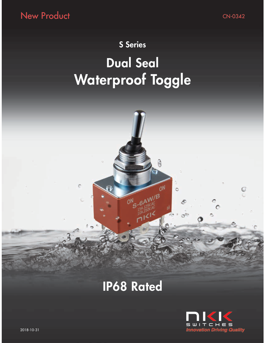
Page 2
General Specifications
Electrical Capacity (Resistive Load)
Power Level: Shown in following tables
Other Ratings
Contact Resistance: 10 milliohms maximum Insulation Resistance: 1,000 megohms minimum @ 500V DC Dielectric Strength: 2,000V AC minimum for 1 minute minimum Mechanical Life: 50,000 operations minimum for S1AWB, S2AWB, S3AWB, S6AWB, S7AWB, S21AWB
30,000 operations minimum for S5AWB, S8AWB, S25AWB, S28AWB
Electrical Life: 25,000 operations minimum Angle of Throw: Shown in following tables
Environmental Data Operating Temperature Range: –30°C through +70°C (–22°F through +158°F)
Sealing: Waterproofing, achieved with boot at base of lever plus o-rings inside and outside of bushing, meets IP68 of IEC60529 Standards (dust tight and protection against effects of temporary immersion). See further explanation on last page.
Processing
Soldering: Manual Soldering: 390°C for 4 seconds, 2 cycles
Distinctive Characteristics
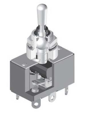
Dual protection with internal o-ring and external rubber washer, sealing the switch to achieve IP68 of IEC60529 Standards (dust tight and water protected against immersion for as long as 30 minutes, in 1.5 meters of water).
Additional panel seal security against wet environments provided by waterproof boot at base of toggle.
Fluid actuation delivered in smooth, sturdy tactile feel.
Sleek design incorporates functionality with polished, chrome-plated actuator paired with waterproof boot.
Superb quality and construction design prohibit entry of foreign particles that may otherwise compromise lever operation.
Page 3
SINGLE POLE WITH SOLDER LUG
| Model | Pole & Throw | Toggle Position/Connected Terminals ( ) = Momentary | Electrical Capacity | α = Angle of Throw | ||||
|---|---|---|---|---|---|---|---|---|
| Down Flat | Center | Up | Resistive | |||||
| AC 125V | AC 250V | DC 30V | ||||||
| S1AWB S2AWB S3AWB S5AWB S8AWB | SPST SPDT SPDT SPDT SPDT | ON 1-3 ON 2-3 ON 2-3 ON 2-3 (ON) 2-3 | NONE NONE OFF NONE OFF | OFF — ON 2-1 ON 2-1 (ON) 2-1 (ON) 2-1 | 15A 15A 15A 15A 15A | 6A 6A 6A 6A 6A | 20A 20A 20A 20A 20A | 24° ± 4° 24° ± 4° 24° ± 4° 20° ± 4° 24° |
| Throw & 2 (COM) SPST INTERNAL SPDT Schematics: CONNECTION 1 3 3 1 | Note: Terminal numbers are actually on the switch | |||||||
DOUBLE POLE WITH SOLDER LUG
| Model | Pole & Throw | Toggle Position/Connected Terminals ( ) = Momentary | Electrical Capacity | α = Angle of Throw | ||||
|---|---|---|---|---|---|---|---|---|
| Down Flat | Center | Up | Resistive | |||||
| AC 125V | AC 250V | DC 30V | ||||||
| S21AWB S6AWB S7AWB S25AWB S28AWB | DPST DPDT DPDT DPDT DPDT | ON 1-3 4-6 ON 2-3 5-6 ON 2-3 5-6 ON 2-3 5-6 (ON) 2-3 5-6 | NONE NONE OFF NONE OFF | OFF — — ON 2-1 5-4 ON 2-1 5-4 (ON) 2-1 5-4 (ON) 2-1 5-4 | 15A 15A 15A 15A 15A | 15A 10A 10A 6A 6A | 15A 20A 20A 20A 20A | 24° ± 4° 24° ± 4° 24° ± 4° 20° ± 4° 24° ± 4° |
| Throw & 2 (COM) 5 DPST INTERNAL DPDT Schematics: CONNECTION 1 3 4 6 3 1 6 4 | Note: Terminal numbers are actually on the switch | |||||||
STANDARD HARDWARE
AT503M Hex Face Nut
Lockwasher
AT537 O-ring
Phosphor Bronze/Chromate Nitrile Butadiene Rubber
Brass with Chrome Plating
(12.1)
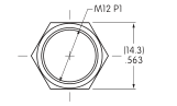
.476
(15.8) Dia .622
(13.8) Dia .543
(1.5)
(16.0) (2.4)
(0.5)
(1.0)
.059
.630 .094
.020
.039
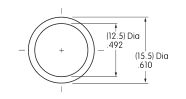
PANEL CUTOUT
Anti-rotation (11.2) .441
(12.5) .492
No Anti-rotation (12.5) Dia .492
Maximum Effective Panel Thickness .157” (4.0mm)
Page 4
TYPICAL SWITCH DIMENSIONS
Solder Lug
Single Pole
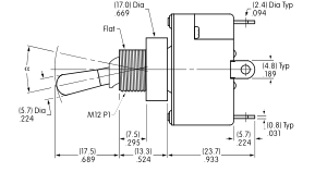
Part No. This Side
3
(30.0)
(10.9)
2 1.181
.429
1
(18.0) .709
S2AWB
S1AWB does not have terminal 2
Double Pole
Solder Lug
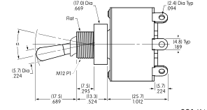
Part No. This Side
3 6
(31.2)
(10.9)
1.228
.429
5 2 4 1
(18.6)
(0.8) Typ
.732
.031
S6AWB
S21AWB does not have terminals 2 & 5
APPLICATION CONSIDERATIONS
The Dual Seal Waterproof S Toggle is designed as a panel seal switch, and not to be used under water.
Material Properties
The material for the waterproof boot is silicone rubber. While silicone rubber has excellent heat, cold and weather resistant properties, it has less durability and oil resistance. The o-ring below the panel is made of nitrile butadiene rubber, which excels in durability and oil and chemical resistance. Its performance is less durable with lower weather and ozone resistant characteristics. Evaluate the products in regard to your application and intended environment with these properties in mind.
Waterproof Test Conditions
Waterproofing is measured
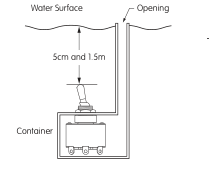
by submersing the switch 5 centimeters from the water surface (see illustration), and opening and closing 50 times at a frequency of 50 – 60 times per minute. The switch is then submersed 1.5 meters from the surface and left in this position for 30 minutes. Repeat opening and closing
Effective Date October 2018
same as previous test. The resulting insulation resistance and voltage capacity are both within the rated values, and water has not entered inside the switch or installation panel.
Panel Installation
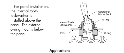
- Construction Equipment
- Medical Equipment
- Hospitality and Restaurant
- Machine Tooling
- Transportation
- Marine Equipment \*
\* Salt spray tested as per Mil-STD-810G section 509.5.
www.nkkswitches.com • 1.877.2BUYNKK (228.9655)
7850 East Gelding Drive • Scottsdale, AZ 85260 • Telephone 480.991.0942 • Fax 480.998.1435