


 Download PDF
S1YL_19 DIOTEC
Document overview
- PDF pages: 3
Technical content
Page 1
Standard Recovery SMD Rectifier Diodes SMD-Gleichrichterdioden mit Standard-Sperrverzug
Version 2019-01-08
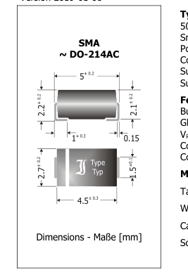
Typical Applications 50/60 Hz Mains Rectification, Smart Meter Input Stage Power Supplies, Polarity Protection Commercial grade Suffix -Q: AEC-Q101 compliant 1) Suffix -AQ: in AEC-Q101 qualification 1)
Features
Budget version of S1Y Glass passivated junction VRRM of 2000 V Compliant to RoHS, REACH, Conflict Minerals 1)
Mechanical Data 1)
Taped and reeled
IFAV = 1 A
VRRM = 2000 V
VF < 1.1 V
IFSM = 22/25 A
Tjmax = 150°C
trr ~ 1500 ns
Typische Anwendungen 50/60 Hz Netzgleichrichtung, Eingangsstufe elektron. Stromzähler Stromversorgungen, Verpolschutz
Standardausführung Suffix -Q: AEC-Q101 konform 1) Suffix -AQ: in AEC-Q101 Qualifikation 1)
Besonderheiten Budget-Version der S1Y Glasspassivierte Sperrschicht VRRM von 2000 V Konform zu RoHS, REACH,
Pb
Konfliktmineralien 1)
Mechanische Daten 1)
7500 / 13“
Gegurtet auf Rolle
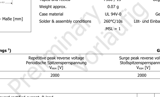
Gewicht ca.
Gehäusematerial
Löt- und Einbaubedingungen
Maximum ratings 2)
Grenzwerte 2)
Type Typ
S1YL/-Q
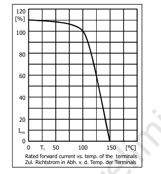
| Max. average forward rectified current, R-load T = 100°C Dauergrenzstrom in Einwegschaltung mit R-Last T | I FAV | 1 A |
|---|---|---|
| Repetitive peak forward current f > 15 Hz T = 100°C Periodischer Spitzenstrom T | I FRM | 4 A |
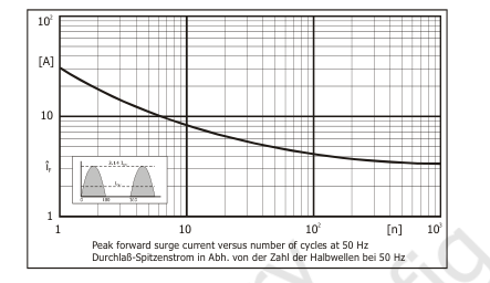
| Peak forward surge current Half sine-wave 50 Hz (10 ms) Stoßstrom in Fluss-Richtung Sinus-Halbwelle 60 Hz (8.3 ms) | I FSM | 22 A 25 A |
| Rating for fusing t < 10 ms Grenzlastintegral | i2t | 2.4 A2s |
| Non-repetitive peak reverse avalanche energy Einmalige Impulsenergie in Sperr-Richtung | E RSM | Not specified Nicht spezifiziert |
| Junction temperature – Sperrschichttemperatur Storage temperature – Lagerungstemperatur | T j T S | -50...+150°C -50...+150°C |
Please note the detailed information on our website or at the beginning of the data book Bitte beachten Sie die detaillierten Hinweise auf unserer Internetseite bzw. am Anfang des Datenbuches TA = 25°C unless otherwise specified – TA = 25°C wenn nicht anders angegeben
Page 2
Characteristics
Kennwerte
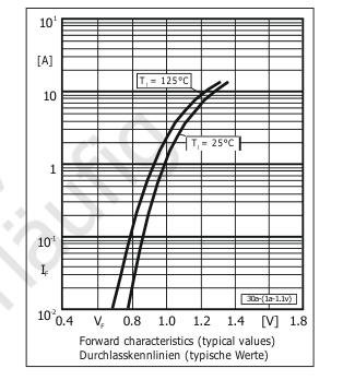
| Forward voltage T = 25°C I = 1 A Durchlass-Spannung j F | V F | < 1.1 |
| Leakage current T = 25°C j V = V Sperrstrom T = 100°C R RRM j | I R | < 5 µA < 50µA |
| Reverse recovery time I = 0.5 A through/über F Sperrverzug I = 1 A to I = 0.25 A R R | t rr | typ. 1500 ns |
| Typical thermal resistance junction-ambient Typischer Wärmewiderstand Sperrschicht-Umgebung | R thA | 75 K/W 1) |
| Typical thermal resistance junction-terminal Typischer Wärmewiderstand Sperrschicht-Anschluss | R thT | 30 K/W |
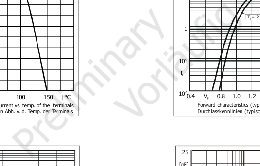
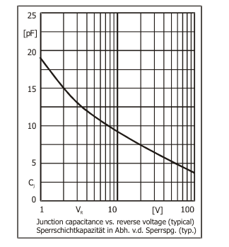
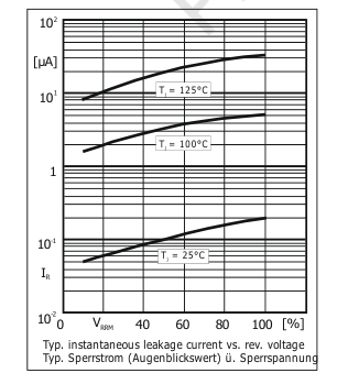
Mounted on P.C. board with 25 mm2 copper pads at each terminal Montage auf Leiterplatte mit 25 mm2 Kupferpad je Anschluss
Page 3
1 0.01[s]0.1 1 10 10
[t ]10 2 3 p
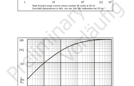
Relative transient thermal impedance vs. pulse duration (typical) Relativer transienter Wärmewiderstand über Impulsdauer (typisch)