
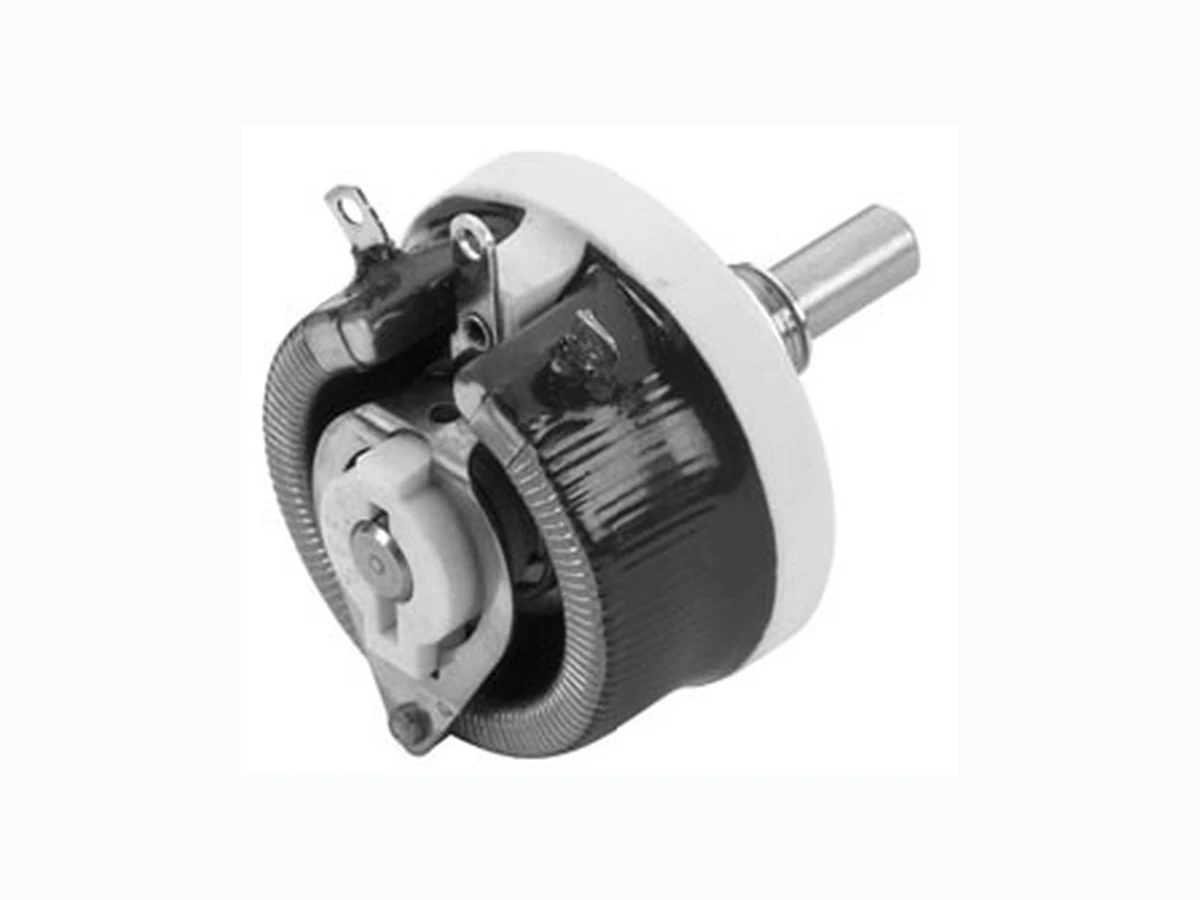
RT25 VISHAY
Document overview
- Manufacturer or author: Provided By www.digicamel.com(free datasheet download site)
- PDF pages: 3
Technical content
Document Number: 50026 For technica l questions, contact: sfer@vishay.com www.vishay.com Revision: 24-Sep-08 83 Wirewound Rheostat/Potentiometer
FEATURES
- 25 W at 25 °C
- CCTU 05-03B (PA1)
- Vitreous - RT style DIMENSIONS in millimeters MECHANICAL SPECIFICATIONS Mechanical Protection Vitreous Mechanical Travel 300° ± 5° Operating Torque 1 to 10 Ncm End Stop Torque 50 Ncm Unit Weight 80 g ENVIRONMENTAL SPECIFICATIONS Temperature Range - 55 °C + 320 °C Climatic Category CCTU 454 CEI 55/200/56 LOCKING DEVICE This is supplied as an option. The available spindle length is according to the panel thickness. Order reference: DBA6 ADAPTATION BOARD This enables 2 point mounting instead of bush mounting. The adaptation board is supplied as an option with 2 mounting screws. Consequently, the available spindle length is reduced by 9.5 mm. ADAPTATION BOARD PANEL CUT OUT DETAILS PANEL CUT OUT DETAILS RT25-PA1 7.6 Ø 10.5 2 holes Ø 5 23.5 23.5 Ø 4.5 12.5 ± 0.5 Ø 10.5 60° Ø 2.2 38 25 4 M10 x 0.75 - 0 Ø 6 - 0.05 129 ± 1 22 ± 228 AS MOUNTING SIDE ELECTRICAL SPECIFICATIONS Ohmic Range 1 Ω to 4.7 kΩ Tolerance Standard ± 10 % Power Rating 25 W at 25 °C Variation Law Standard linear On request sectorial winding Dielectric Strength 1000 VRMS Insulation Resistance 103 MΩ (500 VCC) 1 ± 0.2 2 tightening screws spanner n° 14 max. panel thickness 6.5
www.vishay.com For technical questions, contact: sfer@vishay.com Document Number: 50026 RT25 Vishay Sfernice Wirewound Rheostat/Potentiometer For any special requirement on request: spindle flats, etc. Please supply detailed drawing. MARKING SFERNICE trademark, series, style, power rating in watts, ohmic value (in Ω or kΩ), tolerance (in %), maximum current in A, manufacturing date PARTICULAR CHARACTERISTICS NOMINAL RESISTANCE Ω MAX. SERVICE VOLTAGE V MAX. CURRENT THROUGH WIPER mA 1 5 5000 1.5 6.12 4080 2.2 7.42 3370 3.3 9.08 2750 4.7 10.8 2300 6.8 13 1920 10 15.8 1580 15 19.4 1290 22 23.5 1070 33 28.7 870 47 34.3 730 68 41.2 605 100 50 500 150 61.2 408 220 74.2 337 330 90.8 275 470 108 230 680 130 192 1K 158 158 1.5K 194 129 2.2K 235 107 3.3K 287 87 4.7K 343 73 SPINDLES Ø mm DISTANCE TO MOUNTING PLATE mm SCREW DRIVER SLOT CODE
22 WITH ASF
25 WITHOUT AM
50 WITHOUT AL
DIAL CG57 (OPTION) 4 holes Ø 3.5 Ø 12 100 5647 COMMAND SHAFT 29JF (OPTION) Ø 7 Ø 43
ORDERING INFORMATION
VITREOUS RT 25 L ASF 2K2 10 % B010 e SERIES STYLE SPINDLE LOCKING DEVICE Optional VARIATION LAW SPECIAL DESIGN Method Optional WINDING Optional SPINDLE (Code) for special spindles please supply detailed drawing OHMIC VALUE TOLERANCE PACKAGING LEAD (Pb)-FREE ACC BOUTON CADIAN 29JK CG57 e ACCESORIES MODEL TYPE STYLE LEAD (Pb)-FREE SAP PART NUMBERING GUIDELINES RT 025 ASF 2201 K B XXX MODEL STYLE SPINDLE OHMIC VALUE TOLERANCE PACKAGING SPECIAL DESIGN ACCRF BOUTON 29JF MODEL TYPE STYLE
Document Number: 91000 www.vishay.com Revision: 18-Jul-08 1 Disclaimer Legal Disclaimer Notice Vishay All product specifications and data are subject to change without notice. Vishay Intertechnology, Inc., its affiliates, agents, and employees, and all persons acting on its or their behalf (collectively, “Vishay”), disclaim any and all liability for any errors, inaccuracies or incompleteness contained herein or in any other disclosure relating to any product. Vishay disclaims any and all li ability arising out of the use or application of any product described herein or of any information provided herein to the maximum extent permit ted by law. The product specifications do not expand or otherwise modify Vishay’s terms and conditions of purcha se, including but not limited to the warranty expressed therein, which apply to these products. No license, express or implied, by estoppel or otherwise, to any intellectual property rights is granted by this document or by any conduct of Vishay. The products shown herein are not designed for use in medi cal, life-saving, or life-sustaining applications unless otherwise expressly indicated. Customers using or selling Vishay products not expressly indicated for use in such applications do so entirely at their own risk and agree to fully indemnify Vishay for any damages arising or resulting from such use or sale. Please contact authorized Vishay personnel to obtain written terms and conditions regarding products designed for such applications. Product names and markings noted herein may be trademarks of their respective owners.