

 Download PDF
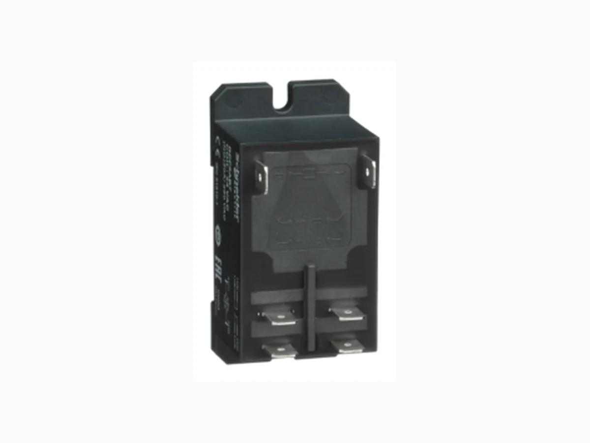
RPF2AB7 SCHNEIDER
Document overview
- PDF pages: 6
Technical content
Page 1
Harmony, Power plug-in relay, 30 A, 2 NO, 24 V
Characteristics
AC
Product availability : Stock - Normally stocked in distribution facility
Price\* : 12.69 USD
Main
Harmony Electromechanical Relays
Range of product Series name
Power
Product or component type
DIN rail/panel mount relay
Device short name
RPF
Contacts type and composition
2 NO
[Uc] control circuit voltage
24 V AC 50/60 Hz
Control type
Without lockable test button
Shape of pin
Flat
Contacts material
Silver tin oxide 25 A -40…131 °F (-40…55 °C) relays side by side without a gap
[Ithe] conventional enclosed thermal
30 A -40…131 °F (-40…55 °C) 13 mm gap between two relays
current Resistive rated load
25 A 28 V DC 30 A 250 V AC
Utilisation coefficient
10 %
Complementary
Mounting support
DIN rail Panel
Control circuit voltage limits
19.2...26.4 V
[Ie] rated operational current
30 A 277 V AC) NO UL 20 A 28 V DC) NO UL 30 A 250 V AC) NO IEC 25 A 28 V DC) NO IEC
[Ui] rated insulation voltage
250 V IEC 300 V UL
[Uimp] rated impulse withstand voltage 4 kV 1.2/50 µs Maximum switching voltage
250 V IEC
\* Price is “List Price” and may be subject to a trade discount – check with your local distributor or retailer for actual price. Aug 9, 2021
Page 2
Maximum switching capacity
7500 VA/700 W
Minimum recommended switching
6000 mW 500 mA / 12 V NO
capacity Operating rate
<= 1200 cycles/hour under load <= 18000 cycles/hour no-load
Mechanical durability
5000000 cycles
Electrical durability
100000 cycles resistive
Average coil consumption
4 VA 60 Hz
Drop-out voltage threshold
= 0.15 Uc
Operate time
25 ms
Release time
25 ms
Average resistance
170 Ohm at 68 °F (20 °C) +/- 15 %
Safety reliability data
B10d = 100000
Protection category
RT II
Test levels
Level A
Operating position
Any position
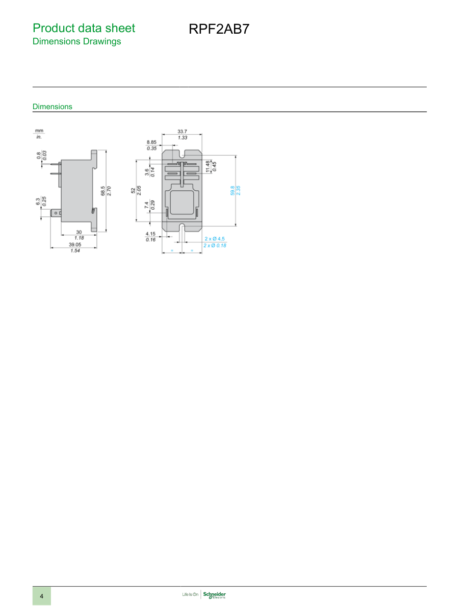
CAD overall width
1.33 in (33.7 mm)
CAD overall height
2.70 in (68.5 mm)
CAD overall depth
1.54 in (39.2 mm)
Net weight
0.18 lb(US) (0.082 kg)
Device presentation
Complete product
Environment
Dielectric strength
2000 V AC between poles with basic 4000 V AC between coil and contact with reinforced 1500 V AC between contacts with micro disconnection
Standards
UL 508 EN/IEC 61810-1 CSA C22.2 No 14
Product certifications
UL CSA GOST CE
Ambient air temperature for storage
-40…185 °F (-40…85 °C)
Ambient air temperature for operation
-40…131 °F (-40…55 °C) 3 gn +/- 1 mm 10…150 Hz)5 cycles in operation
Vibration resistance
10 gn +/- 1 mm 10…150 Hz)5 cycles not operating
IP degree of protection
IP40 conforming to EN/IEC 60529
Shock resistance
10 gnin operation 30 gnnot operating
Pollution degree
3
Ordering and shipping details
Category
21127 - ZELIO ICE CUBE RELAYS
Discount Schedule
CP2
GTIN
03389119401524
Nbr. of units in pkg.
1
Package weight(Lbs)
3.25 oz (92 g)
Returnability
Yes
Country of origin
CN
Packing Units
Unit Type of Package 1
PCE
Package 1 Height
1.65 in (4.2 cm)
Package 1 width
1.38 in (3.5 cm)
Page 3
Package 1 Length
2.72 in (6.9 cm)
Offer Sustainability
Sustainable offer status
Green Premium product WARNING: This product can expose you to chemicals including: Nickel compounds, which is known
California proposition 65
to the State of California to cause cancer, and Di-isodecyl phthalate (DIDP), which is known to the State of California to cause birth defects or other reproductive harm. For more information go to www.P65Warnings.ca.gov
REACh Regulation
REACh Declaration
REACh free of SVHC
Yes Pro-active compliance (Product out of EU RoHS legal scope)
EU RoHS Directive
EU RoHS Declaration
Toxic heavy metal free
Yes
Mercury free
Yes
RoHS exemption information
Yes
China RoHS Regulation
China RoHS declaration
Environmental Disclosure
Product Environmental Profile The product must be disposed on European Union markets following specific waste collection and
WEEE
never end up in rubbish bins.
Contractual warranty
Warranty
18 months
Page 4
Page 5
Connections and Schema
Wiring Diagram
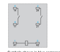
Symbols shown in blue correspond to Nema marking.
Page 6
Performance Curves
Electrical Durability of Contacts
AC Resistive load
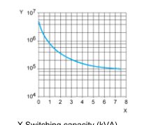
X Switching capacity (kVA) Y Durability (number of operating cycles)
AC Reduction coefficient for inductive load (depending on power factor cos ϕ)
Durability (inductive load) = durability (resistive load) x reduction coefficient.
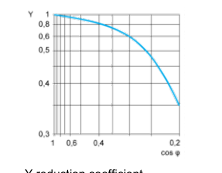
Y reduction coefficient
Maximum switching capacity on DC resistive load
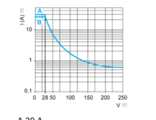
A 30 A B 25 A Note : These are typical curves, actual durability depends on load, environment, duty cycle, etc.