
RP12 VISHAY
Document overview
- Manufacturer or author: Provided By www.digicamel.com(FREE DATASHEET DOWNLOAD SITE)
- PDF pages: 4
Technical content
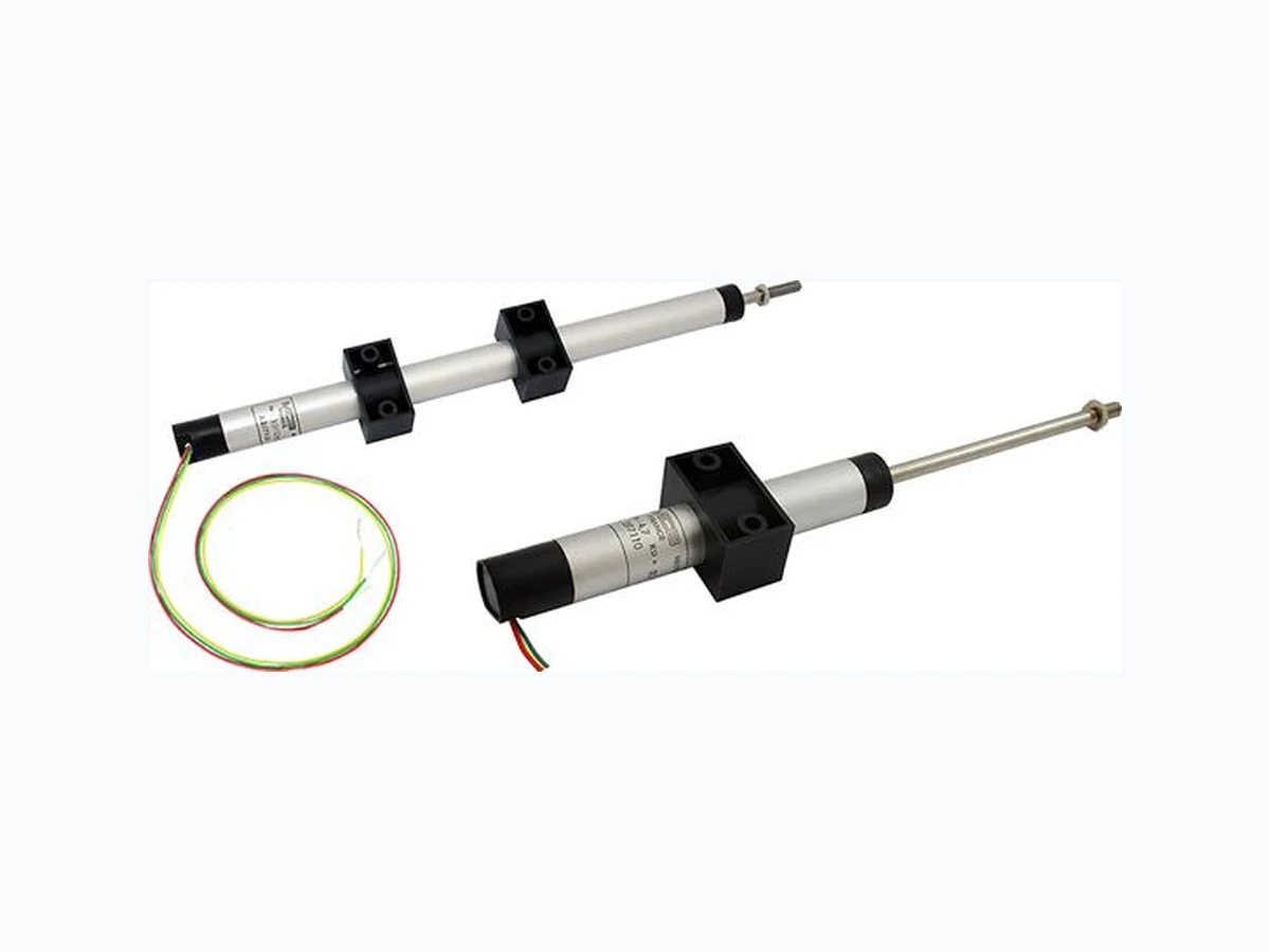
www.vishay.com Vishay MCB Revision: 25-Jan-18 1 Document Number: 32524 For technical questions, contact: mcbprecisionpot@vishay.com THIS DOCUMENT IS SUBJECT TO CHANGE WITHOUT NOTICE. THE PRODUCTS DESCRIBED HEREIN AND THIS DOCUMENT ARE SUBJECT TO SPECIFIC DISCLAIMERS, SET FORTH AT www.vishay.com/doc?91000 Analog Linear Displacement Sensor DESIGN SUPPORT TOOLS
FEATURES
- Conductive plastic potentiometer technology. Infinite resolution
- Anodized light alloy housing
- Stainless steel floating shaft
- Flange mounting
- W i r e o u t p u t s
- Material categorization: fo r definitions of compliance please see www.vishay.com/doc?99912 Note
- Nothing stated herein shall be construed as a guarantee of quality or durability QUICK REFERENCE DATA Sensor type LINEAR, conductive plastic Output type Output by wires Market appliance Industrial Dimensions Diameter 1/2" (12.7 mm) click logo to get started Available Models ELECTRICAL SPECIFICATIONS PARAMETER Theoretical electrical travel UET +1 mm to 0 mm Independent linearity standard ± 0.5 % Independent linearity optional ± 0.1 % (UET 50 mm), ± 0.25 % (UET 50 mm) Tolerance on R n ± 20 % Temperature coefficient -300 ± 300 ppm/°C Wiper current 1 mA Recommended load impedance 1000 R n Dielectric strength 500 V RMS, 50 Hz, 1 min Insulation resistance 10 G at 500 VDC Output smoothness 0.1 % Useful electrical travel (UET) 10 mm 25 mm 50 mm 75 mm 100 mm 150 mm 200 mm 250 mm 300 mm Power rating at +70 °C Total resistance Rn 2.2 k 4.7 k 4.7 k 10 k 10 k 10 k 10 k 22 k 22 k MECHANICAL SPECIFICATIONS PARAMETER Mechanical travel UET + 4 mm Driving force 2 N Backlash < 15 μm Protection class IP 64 Maximum displacement speed 1.5 m/s Mounting 1 block (UET < 100 mm) and 2 blocks (UET 100 mm) Useful electrical travel (UET) 10 mm 25 mm 50 mm 75 mm 100 mm 150 mm 200 mm 250 mm 300 mm Weight Shaft + wiper 4 g 6 g 8 g 11 g 13 g 18 g 23 g 28 g 33 g Sensor 20 g 22 g 27 g 30 g 40 g 51 g 65 g 75 g 86 g PERFORMANCE PARAMETER Operating temperature range -40 °C to +105 °C Storage temperature range -55 °C to +125 °C Life 20M cycles
www.vishay.com Vishay MCB Revision: 25-Jan-18 2 Document Number: 32524 For technical questions, contact: mcbprecisionpot@vishay.com THIS DOCUMENT IS SUBJECT TO CHANGE WITHOUT NOTICE. THE PRODUCTS DESCRIBED HEREIN AND THIS DOCUMENT ARE SUBJECT TO SPECIFIC DISCLAIMERS, SET FORTH AT www.vishay.com/doc?91000 SAP PART NUMBERING GUIDELINES MODEL USEFUL ELECTRICAL TRAVEL (m m) TYPE VALUE LINEARITY LEADS PACKAGING RP12 010 025 050 075 100 150 200 250 300 L = linear 222 = 2K2 472 = 4K7 103 = 10K 223 = 22K In accordance with UET, see “Electrical Specifications” B = 0.5 % W = wire b = bulk DIMENSIONS in millimeters FRONT PIVOT OPTION (ON REQUEST) REAR PIVOT OPTION (ON REQUEST) STRAIGHT OR RIGHT ANGLE CONNECTOR OPTION (ON REQUEST) 12.7Ø Mounting block (on request) 2 x Ø 3.2 diam. holes Teflon wires gauge 26 length 300
25 L = UET + 37
18Ø Ø5thickne ss 8 L = 44 ± 2.5 18Ø Ø5thickne ss 8 27 ± 1.5 38.5 18Ø 26.5 Wires L = UET + 56.5 35 15Ø L = UET + 37 58 31.2 37.235 Cable customer Cable customer 15Ø
www.vishay.com Vishay MCB Revision: 25-Jan-18 3 Document Number: 32524 For technical questions, contact: mcbprecisionpot@vishay.com THIS DOCUMENT IS SUBJECT TO CHANGE WITHOUT NOTICE. THE PRODUCTS DESCRIBED HEREIN AND THIS DOCUMENT ARE SUBJECT TO SPECIFIC DISCLAIMERS, SET FORTH AT www.vishay.com/doc?91000 ELECTRICAL DIAGRAM Direction of wiper displacement with shaft extended CONNECTION OPTIONS (on request)
- Other linearity
- Probe version for UET < 100 mm (spring and tip)
- Low driving force version ( 30 cN/ IP 50)
- Lateral or axial cable output
- Binder 713-M12 series straight connector output
- Binder 713-M12 series right angle connector output
- Male socket fitted on connector
- Additional mounting block
- Front pivot
- Rear pivot (only with lateral cable output) Green Red Yellow
www.vishay.com Vishay Revision: 08-Feb-17 1 Document Number: 91000 Disclaimer ALL PRODUCT, PRODUCT SPECIFICATIONS AND DATA AR E SUBJECT TO CHANGE WITH OUT NOTICE TO IMPROVE RELIABILITY, FUNCTION OR DESIGN OR OTHERWISE. Vishay Intertechnology, Inc., its affiliates, agents, and employee s, and all persons acting on it s or their behalf (collectivel y, “Vishay”), disclaim any and all liability for any errors, inaccuracies or incompleteness contained in any datasheet or in any other disclosure relating to any product. Vishay makes no warranty, representation or guarantee regarding the suitability of th e products for any particular purpose or the continuing production of any product. To the maximum extent permitted by applicable law, Vishay disclaims (i) any and all liability arising out of the application or use of any product , (ii) any and all liability, including without limitation specia l, consequential or incidental damages, and (iii) any and all implied warranties, includ ing warranties of fitness for particular purpose, non-infringement and merchantability. Statements regarding the suitability of products for certain types of applicatio ns are based on Vishay’s knowledge of typical requirements that are often placed on Vishay products in generic applications. Such statements are not binding statements about the suitability of products for a particular applic ation. It is the customer’s responsibility to validate tha t a particular product with the prope rties described in the product sp ecification is suitable for use in a particular application. Parameters provided in datasheets and / or specifications may vary in different ap plications and performance may vary over time. All operating parameters, including typical parameters, must be validated for each customer application by the customer’s technical experts. Product specifications do not expand or otherwise modify Vishay’s term s and conditions of purchase, including but not limited to the warranty expressed therein. Except as expressly indicated in writing, Vishay products are not designed for use in medical, life-saving, or life-sustaining applications or for any other application in which the failure of the Vishay product could result in personal injury or death. Customers using or selling Vishay product s not expressly indicated for use in such applications do so at their own risk. Please contact authorized Vishay personnel to obtain writ ten terms and conditions rega rding products designed for such applications. No license, express or implied, by estoppel or otherwise, to any intellectual property rights is gran ted by this document or by any conduct of Vishay. Product names and markings noted herein may be trademarks of their respective owners. © 2017 VISHAY INTERTECHNOLOGY, INC. ALL RIGHTS RESERVED