

 Download PDF
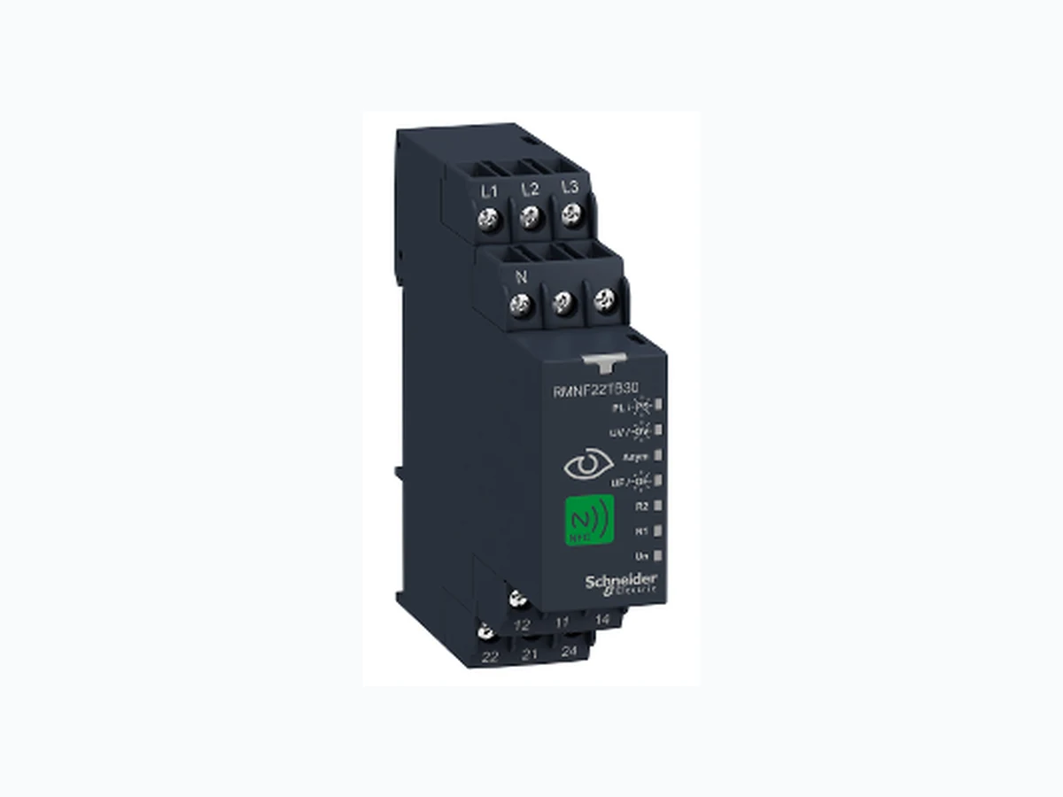
RMNF22TB30 SCHNEIDER
Document overview
- PDF pages: 9
Technical content
Page 1
Harmony, NFC 3-phase monitoring relay, 8 A,
Characteristics
2CO, multifunction, 208…480 V AC
Product availability : Non-Stock - Not normally stocked in distribution facility
Price\* : 90.00 USD
Main
Range of product
Harmony Control Relays
Product or Component Type
3-phase control relay
Relay Type
Control relay
Phase
3 phase
Relay name
RMNF22
Relay monitored parameters
Phase sequence Phase failure detection Overvoltage detection Undervoltage detection Overfrequency and underfrequency Asymmetry
Supported OS
Android
Software Version
V4.4 and above Zelio NFC downloadable from Google Play store)
App for product Product Compatibility
NFC enabled mobile device
Time delay type
On-delay 0.1 s...60 min Off-delay 0.1 s...60 min
Switching capacity in VA
2000 VA
Complementary
NFC operating frequency
13.56 MHz
Maximum RF power transmitted
0.0002 mW
Reset time
1500 ms at maximum voltage
Maximum switching voltage
250 V AC
Minimum switching current
100 mA 6 V
Maximum switching current
8 A AC
[Us] rated supply voltage
208...480 V AC line to line
\* Price is “List Price” and may be subject to a trade discount – check with your local distributor or retailer for actual price. Sep 13, 2021
Page 2
120...277 V AC line to neutral
Supply voltage limits
166.4…576 V AC line to line 96…332.4 V AC line to neutral
Power consumption in VA
4 VA 480 V AC 60 Hz
On-load factor
100 %
Supply voltage frequency
50...60 Hz +/- 10 %
Output contacts
2 C/O
Setting accuracy of the switching
+/- (1.5 % + 1 V)
threshold Setting accuracy of time delay
+/- 3 % 10 s...60 min +/- 300 ms 0...10 s
Hysteresis
3 % fixed phase failure detection 166...576 V adjustable overvoltage and undervoltage detection (line to line)
Alarm threshold
96...332 V adjustable overvoltage and undervoltage detection (line to neutral) 5...150 V adjustable asymmetry 45...66 Hz adjustable overfrequency or underfrequency
Run-up delay at power-up max
650 ms 150 ms measurement cycle as true rms value
Maximum measuring cycle Repeat accuracy
+/- 0.5 % input circuit +/- 3 % time delay
Setting accuracy of the switching
+/- (1.5 % + 1 V)
threshold Measurement error
< 0.05 %/Hz with frequency variation < 0.05 %/°C with temperature variation
Response time
<= 300 ms > 100 MOhm at 500 V DC conforming to IEC 60255-27
Insulation resistance [Ui] rated insulation voltage
400 V
[Uimp] rated impulse withstand voltage 4 kV 1.2/50 µs
2.5 kV AC 50 Hz, 1 min IEC 60255-27
Dielectric test voltage Mounting position
Any position Screw terminals, 2 x 0.5...2 x 2.5 mm² (AWG 20...AWG 14) solid without cable end
Connections - terminals
Screw terminals, 2 x 0.5...2 x 1.5 mm² AWG 20...AWG 16) flexible with cable end Screw terminals, 1 x 0.5...1 x 3.3 mm² (AWG 20...AWG 12) solid without cable end Screw terminals, 1 x 0.5...1 x 2.5 mm² AWG 20...AWG 14) flexible with cable end 5.31…8.85 lbf.in (0.6…1 N.m) IEC 60947-1
Tightening torque
5.3…8.8 lbf.in (0.60…0.99 N.m) IEC 60947-1
Housing material
Self-extinguishing plastic
Local signalling
Un, green LED steady)power ON R1, amber LED steady)relay energised R1, amber LED blinking)timing in progress R2, amber LED steady)relay energised R2, amber LED blinking)timing in progress PL, red LED steady)alarm phase failure triggered PS, red LED blinking)alarm phase sequence failure triggered UV, red LED steady)alarm undervoltage failure triggered OV, red LED blinking)alarm overvoltage failure triggered UF, red LED steady)alarm underfrequency failure triggered OF, red LED blinking)alarm overfrequency failure triggered ASYM, red LED steady)alarm asymmentry failure triggered 35 mm DIN rail conforming to EN/IEC 60715
Mounting support Electrical durability
100000 cycles
Mechanical durability
10000000 cycles
Utilisation category
AC-15 conforming to IEC 60947-5-1 DC-13 conforming to IEC 60947-5-1 AC-1 conforming to IEC 60947-4-1 DC-1 conforming to IEC 60947-4-1
[Ith] conventional free air thermal
8 A
current Contacts material
Cadmium free
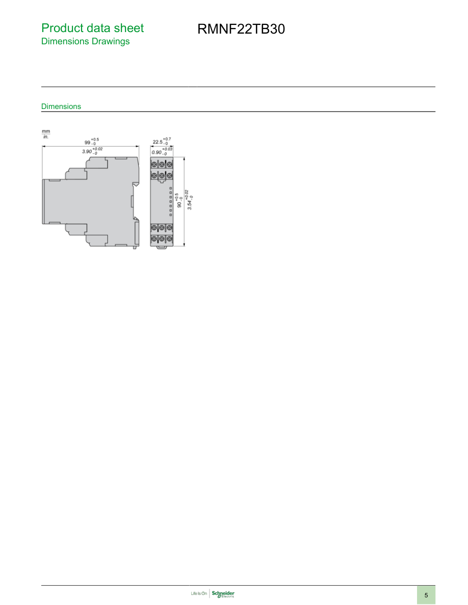
Width
0.89 in (22.5 mm)
Height
3.54 in (90 mm)
Page 3
Depth
3.90 in (99 mm)
Contacts type and composition
2 C/O
Product Weight
0.28 lb(US) (0.125 kg)
Environment
Immunity to microbreaks
10 ms Voltage dips and interruptions immunity test 70 % 25/30 cycles) IEC 61000-4-11
Electromagnetic compatibility
Electrostatic discharge - test level: 6 kV level 3 (contact discharge) conforming to IEC 61000-4-2 Conducted and radiated emissions class B group 1 conforming to CISPR 11 Conducted and radiated emissions class B conforming to CISPR 22 Radiated radio-frequency electromagnetic field immunity test - test level: 10 V/m level 3 conforming to IEC 61000-4-3 Immunity for industrial environments conforming to EN/IEC 61000-6-2 1 MHz damped oscillating wave 2.5 kV CM, 1 kV DMcriteria B IEC 61000-4-18 Voltage dips and interruptions immunity test 0 % 0.5...25 cycles) IEC 61000-4-11 Magnetic field at power frequency 30 A/m (continuous)-300 A/m (1-3 s)level 4 IEC 61000-4-8
Surge immunity test - test level: 2 kV level 4 (differential mode) conforming to IEC 61000-4-5 Immunity for residential, commercial and light-industrial environments conforming to EN/IEC 61000-6-1 Voltage dips and interruptions immunity test 40 % 10/12 cycles) IEC 61000-4-11 Voltage interruptions 0 % 250/300 cycles)criteria C IEC 61000-4-29 Electrical fast transient/burst immunity test 4 kV direct)criteria B IEC 61000-4-4 Emission standard for industrial environments conforming to EN/IEC 61000-6-4 Emission standard for residential, commercial and light-industrial environments EN/IEC 61000-6-3 Surge immunity test - test level: 4 kV level 4 (common mode) conforming to IEC 61000-4-5
Electrostatic discharge - test level: 8 kV level 3 (air discharge) conforming to IEC 61000-4-2 Conducted RF disturbances level 3 conforming to IEC 61000-4-6
Standards
EN/IEC 60255-1
Product Certifications
CE UL CSA CCC EAC RCM 2014/30/EU - electromagnetic compatibility
Directives
2014/35/EU - low voltage directive 2014/53/EU - radio equipment directive
Ambient Air Temperature for Storage
-40…158 °F (-40…70 °C)
Ambient air temperature for operation
-4…140 °F (-20…60 °C) 93…97 % 77…131 °F (25…55 °C) IEC 60068-2-30
Relative humidity
0.075 mm 10…58.1 Hz) not in operation IEC 60068-2-6
Vibration resistance
1 gn 58.1…150 Hz) not in operation IEC 60068-2-6 0.035 mm 10…58.1 Hz) in operation IEC 60068-2-6 0.5 gn 58.1…150 Hz) in operation IEC 60068-2-6 15 gn 11 ms) not in operation IEC 60068-2-27
Shock resistance
5 gn 11 ms) in operation IEC 60068-2-27 IP20 (terminals) conforming to IEC 60529
IP degree of protection
IP40 IEC 60529 housing) IP40 IEC 60529 front panel)
Pollution degree
3 conforming to IEC 60664-1 3 conforming to UL 508
Overvoltage category
III conforming to IEC 60664-1 III conforming to UL 508
Ordering and shipping details
22376 - RELAYS-MEASUREMENT(RM4)
Category Discount Schedule
CP2
GTIN
3606489591120
Nbr. of units in pkg.
1
Package weight(Lbs)
4.80 oz (136 g)
Returnability
No
Page 4
Packing Units
Unit Type of Package 1
PCE
Package 1 Height
3.78 in (9.6 cm)
Package 1 width
0.98 in (2.5 cm)
Package 1 Length
4.25 in (10.8 cm)
Unit Type of Package 2
S02
Number of Units in Package 2
36
Package 2 Weight
12.30 lb(US) (5.578 kg)
Package 2 Height
5.91 in (15 cm)
Package 2 width
11.81 in (30 cm)
Package 2 Length
15.75 in (40 cm)
Offer Sustainability
Sustainable offer status
Green Premium product WARNING: This product can expose you to chemicals including: Nickel compounds, which is known
California proposition 65
to the State of California to cause cancer, and Di-isodecyl phthalate (DIDP), which is known to the State of California to cause birth defects or other reproductive harm. For more information go to www.P65Warnings.ca.gov
REACh Regulation
REACh Declaration Pro-active compliance (Product out of EU RoHS legal scope)
EU RoHS Directive
EU RoHS Declaration
Mercury free
Yes
RoHS exemption information
Yes
China RoHS Regulation
China RoHS declaration
Environmental Disclosure
Product Environmental Profile
Circularity Profile
End of Life Information The product must be disposed on European Union markets following specific waste collection and
WEEE
never end up in rubbish bins.
Page 5
Page 6
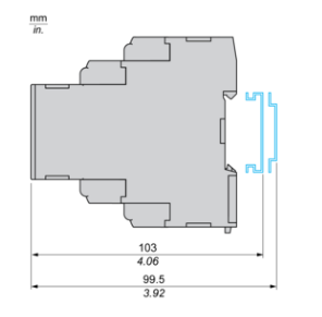
Mounting and Clearance
Mounting and Clearance
Rail Mounting
Page 7
Connections and Schema
3-Phase Control Relay
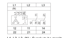
L1, L2, L3, (N) : Supply to be monitored (with or without neutral) 12, 11, 14 : 1st C/O contact of output relay 22, 21, 24 : 2nd C/O contact of output relay
Page 8
Technical Description
Function Diagrams
Phase Loss and Phase Sequence
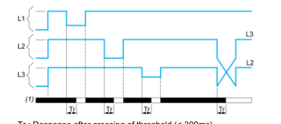
Tr : Response after crossing of threshold (< 300ms) L1, L2, L3 : Phases of the supply voltage monitored Alarm status:
- White color: Alarm triggered
- Black color: Alarm not triggered
(1) : Alarm
Overvoltage & Undervoltage
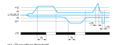
U : Overvoltage threshold H : Hysteresis U< : Undervoltage threshold L1, L2, L3 : Phases of the supply voltage monitored Tt : Time delay after crossing of threshold (adjustable on app) Alarm status:
- White color : Alarm triggered
- Black color : Alarm not triggered
(1) : Alarm
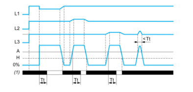
Asymmetry
Page 9
L1, L2, L3 : Phases of the supply voltage monitored A : Asymmetry threshold (adjustable from 5...150V of the nominal supply voltage) H : Hysteresis Tt : Time delay after crossing of threshold (adjustable on app) Alarm status:
- White color : Alarm triggered
- Black color : Alarm not triggered
(1) : Alarm
Over Frequency & Under Frequency
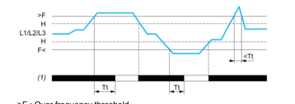
F : Over frequency threshold H : Hysteresis F< : Under frequency threshold L1, L2, L3 : Line frequency Tt : Time delay after crossing of threshold (adjustable on app) Alarm status:
- White color : Alarm triggered
- Black color : Alarm not triggered
(1) : Alarm