
DATASHEET SEARCH SITE
Document overview
- Manufacturer or author: Provided By www.digicamel.com(FREE DATASHEET DOWNLOAD SITE)
- PDF pages: 11
Technical content
Features
Multiple frequency outputs CMOS, LVPECL, LVDS, or HCSL output options Extended temperature range Tight frequency stability Wide frequency range Low height profile Fast sample turnaround Specifications ----- 1.0 SPECIFICATION REFERENCES Line Parameter
Description
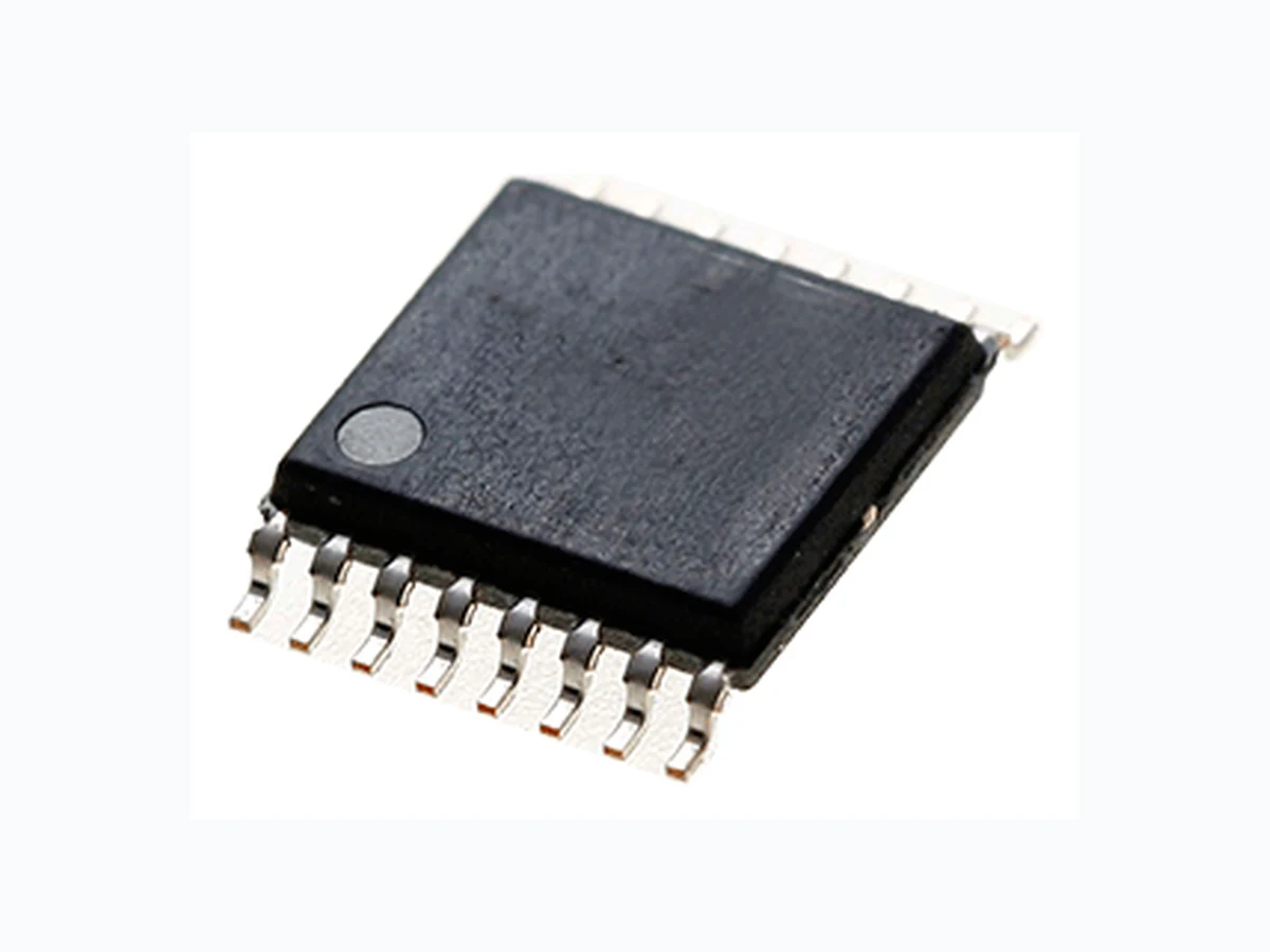
1.1 Model Description RMF3225S - 14 QFN, or RMF3225S - 16 TSSOP 1.2 Reference Number 1.3 Rakon Part Number ----- 2.0 FREQUENCY CHARACTERISTICS Line Parameter Test Condition Value Unit 2.1 Frequency A 10 to 460 MHz 2.2 Frequency B 10 to 460 MHz 2.3 Operating Temperature Range -55°C to 125°C upon request -40 to 85 2.4 Frequency Stability Including initial tolerance, Temperature range, Supply variation, Load variation and 10 years aging at 25°C ±25 to 100 ppm 2.5 Temperature Stability Temperature range only ±10 to 25 ppm ----- Page 1
3.0 POWER SUPPLY Line Parameter Test Condition Value Unit 3.1 Supply Voltage (VDD) With a tolerance of ±10% 3.3 V 3.2 Supply Voltage (VDD) With a tolerance of ±10% 2.5 V 3.3 Supply Current For LVCMOS 40 max mA 3.4 Supply Current For LVPECL 65 max mA 3.5 Supply Current For LVDS 40 max mA 3.6 Supply Current For HCSL 50 max mA ----- 4.0 OUTPUT CHARACTERISTICS - CMOS (UP TO 170 MHz) Line Parameter Test Condition Value Unit 4.1 Output Voltage (Vol) 15pF load 10 max %VDD 4.2 Output Voltage (Voh) 15pF load 90 min %VDD 4.3 Duty Cycle @ 50% VDD 45 to 55 4.4 Rise Time/Fall Time 80%/20% 2 max ns 4.5 RMS Phase Jitter Integrated 12 kHz to 20 MHz at 125 MHz 2 max ps ----- 5.0 OUTPUT CHARACTERISTICS - LVPECL ONLY Line Parameter Test Condition Value Unit 5.1 Output Voltage (Vol) 50Ω nominal load. (VDD - 1.55V) max. 5.2 Output Voltage (Voh) 50Ω nominal load. (VDD - 1.08V) min. 5.3 Duty Cycle Measured at 1.25V 48 to 52 5.4 Rise Time/Fall Time 80%/20% 0.6 max ns 5.5 RMS Phase Jitter Integrated 12 kHz to 20 MHz at 156.25 MHz 2 max ps ----- 6.0 OUTPUT CHARACTERISTICS - LVDS ONLY Line Parameter Test Condition Value Unit 6.1 Differential Output: Voltage Swing (Vod) 350 mV 6.2 Duty Cycle Measured at 1.25V 48 to 52 6.3 Rise Time / Fall Time RL = 50Ω / CL = 2pF 0.6 max ns 6.4 RMS Phase Jitter Integrated 12 kHz to 20 MHz at 156.25 MHz 2 max ps ----- 7.0 OUTPUT CHARACTERISTICS - HCSL ONLY Line Parameter Test Condition Value Unit 7.1 Output Voltage (Vol) 0.1 max VDD 7.2 Output Voltage (Voh) 0.725 min VDD 7.3 Duty Cycle 48 to 52 7.4 Rise Time/Fall Time 80%/20% 0.6 max ns 7.5 RMS Phase Jitter Integrated 12 kHz to 20 MHz 2 max ps ----- Page 2
8.0 PIN CONNECTIONS - 14 QFN Line Parameter 8.1 Pin 1 Enable/Disable (>70% VDD is Enable. <30% VDD is Disable) 8.2 Pin 2 GND or NC 8.3 Pin 3 GND or NC 8.4 Pin 4 VSS 8.5 Pin 5 GND or NC 8.6 Pin 6 GND or NC 8.7 Pin 7 GND or NC 8.8 Pin 8 Output B 8.9 Pin 9 Complimentary Output B (PECL/LVDS/HCSL) or NC 8.10 Pin 10 Complimentary Output A (PECL/LVDS/HCSL) or NC 8.11 Pin 11 Output A 8.12 Pin 12 VDDB 8.13 Pin 13 VDDA 8.14 Pin 14 GND or NC ----- 9.0 PIN CONNECTIONS - 16 TSSOP Line Parameter 9.1 Pin 1 GND or NC 9.2 Pin 2 GND or NC 9.3 Pin 3 GND or NC 9.4 Pin 4 GND or NC 9.5 Pin 5 GND or NC 9.6 Pin 6 Enable/Disable (>70% VDD is Enable. <30% VDD is Disable) 9.7 Pin 7 VSS 9.8 Pin 8 GND or NC 9.9 Pin 9 GND or NC 9.10 Pin 10 Output B 9.11 Pin 11 Complimentary Output B (PECL/LVDS/HCSL) or NC 9.12 Pin 12 GND or NC 9.13 Pin 13 GND or NC 9.14 Pin 14 Complimentary Output A (PECL/LVDS/HCSL) or NC 9.15 Pin 15 Output A 9.16 Pin 16 VDD ----- 10.0 PACKAGE DETAILS Line Parameter 10.1 Package QFN-14 (3.2 x 2.5 mm) or TSSOP-16 (6.4 x 5.0 mm) 10.2 Line 1 Logo 10.3 Line 2 [FFFFFF-FFF] FFFFFF-FFF=Factory information 10.4 Line 3 [YYWW] YY=Last two digits of the year, WW=A two digit week number 10.5 Line 4 [o LLLL] Dot=Pin 1 indicator, LLLL=Lot code ----- Page 3
11.0 ENVIRONMENTAL SPECIFICATION Line Parameter 11.1 Mechanical Shock MIL-STD-883, Method 2002 11.2 Storage Temperature Range -55 to 150°C 11.3 Humidity After 48 hours at 85°C ±2°C 85% relative humidity non-condensing 11.4 Thermal Shock MIL-STD-883, Method 1011 11.5 Vibration MIL-STD-883, Method 2007 11.6 Gross and Fine Leak MIL-STD-883, Method 1014 11.7 RoHS Compliant Yes 11.8 Halogen Free Yes 11.9 REACH Compliance Yes (EC Regulation No. 1907/2006) ----- 12.0 MANUFACTURING INFORMATION Line Parameter 12.1
14 QFN Packaging
Tape and Reel. Standard packing quantity is 1000 or 3000 units per D180 mm reel. 3000 or 5000 units per D330 mm reel 12.2
16 TSSOP Packaging
12.3 Reflow Solder reflow process as per attached profile Page 4
Drawing Name: RMF3225S Model 14 QFN (package Z) Page 5
Drawing Name: XO 14 QFN Test Circuit (Package Z) Page 6
Drawing Name: XO/VCXO 3225 Tape & D180 Reel (Package Z) Page 7
Drawing Name: XO/VCXO 3225 Tape & D330 Real (Package Z) Page 8
Drawing Name: RMF3225S Model 16 TSSOP (Package Z) Page 9
Drawing Name: XO 16 TSSOP Test Circuit (Package Z) Page 10
Drawing Name: Pb-Free Reflow Page 11