


 Download PDF
RMF RFE
Document overview
- PDF pages: 1
Technical content
Page 1
SURFACE MOUNT RESISTORS
RoHS
RMF Series: Fusible Thick Film Surface Mount
INTRODUCTION
D
RFE International, Inc. offers a wide range of chip
resistors to meet your application requirements. They are
made with metal glazed thick film on a high purity
ceramic substrate which is overcoated for stability and
protection. These resistors are lead free. The RMF
H
Series Fusible Resistor is ideal for circuits where a
predictable fusing time is important. The RMF Series is
AEC-Q200 Qualified.
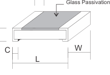
DIMENSIONS
| Type | Dimensions (mm) | ||||
|---|---|---|---|---|---|
| L | W | H | C | D | |
| RMF04 (0402) | 1.0 + 0.1 | 0.5 + 0.05 | 0.35 + 0.05 | 0.20 + 0.1 | 0.2 + 0.1 |
| RMF06 (0603) | 1.6 + 0.2 | 0.8 + 0.15 | 0.50 + 0.1 | 0.30 + 0.2 | 0.3 + 0.15 |
| RMF10 (0805) | 2.0 + 0.2 | 1.25 + 0.15 | 0.50 + 0.15 | 0.40 + 0.2 | 0.3 + 0.15 |
| RMF12 (1206) | 3.2 + 0.2 | 1.6 + 0.12 | 0.60 + 0.15 | 0.45 + 0.2 | 0.4 + 0.2 |
| RMF25 (1210) | 3.2 + 0.2 | 2.5 + 0.2 | 0.60 + 0.15 | 0.50 + 0.2 | 0.5 + 0.2 |
| RMF50 (2010) | 5.0 + 0.2 | 2.5 + 0.2 | 0.60 + 0.1 | 0.60 + 0.2 | 0.6 + 0.2 |
| RMF1W (2512) | 6.3 + 0.2 | 3.1 + 0.2 | 0.65 + 0.1 | 0.60 + 0.2 | 0.6 + 0.2 |
RATINGS
| Type | Power Rating | Max Working Voltage | Max Overload Voltage | 30 Second Fusing Power | Temp. Coefficient (ppm / °C) | Available Range |
|---|---|---|---|---|---|---|
| RMF04 (0402) | 0.1W | 50V | 100V | 2.5W | 1 Ω- 47 Ω + 600 ppm 48Ω ~ 470Ω + 400 ppm 471Ω ~ 10KΩ + 200 ppm | 1Ω ~ 1KΩ |
| RMF06 (0603) | 0.125W | 50V | 100V | 3W | 1Ω ~ 1.8KΩ | |
| RMF10 (0805) | 0.15W | 150V | 300V | 3.25W | 1 Ω ~ 3KΩ | |
| RMF12 (1206) | 0.25W | 200V | 400V | 5W | 1Ω ~ 5.1KΩ | |
| RMF25 (1210) | 0.5W | 200V | 400V | 7.5W | 1 Ω ~ 6 .2KΩ | |
| RMF50 (2010) | 0.75W | 200V | 400V | 11.25W | 1Ω ~ 7.5KΩ | |
| RMF1W (2512) | 1.0W | 200V | 400V | 15W | 1Ω ~ 10KΩ |
- Standard Resistance Range is 1 thru 10K on EIA Standard Value Table E-24
- Standard Resistance Tolerance +5% or 10%
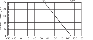
DERATING CURVE
PART NUMBER EXAMPLE
Operating Temp. Range -55°C ~ +155°
RMF 50 R - 4R7 - J
Ambient Temperature (°C)
RFE International • Tel:(949) 833-1988 • Fax:(949) 833-1788 • E-Mail Sales@rfeinc.com
C2BB06 2014.10.13