
DATASHEET SEARCH SITE
Document overview
- Manufacturer or author: Provided By www.digicamel.com(FREE DATASHEET DOWNLOAD SITE)
- PDF pages: 4
Technical content
RMB, RMBS www.vishay.com Vishay Sfernice Revision: 23-Sep-13 1 Document Number: 50010 For technical questions, contact: sferfixedresistors@vishay.com THIS DOCUMENT IS SUBJECT TO CHANGE WITHOUT NOTICE. THE PRODUCTS DESCRIBED HEREIN AND THIS DOCUMENT ARE SUBJECT TO SPECIFIC DISCLAIMERS, SET FORTH AT www.vishay.com/doc?91000 Molded Precision Wirewound Resistors Axial Leads
FEATURES
- 0.75 W to 3 W at 25 °C
- N F C 8 3 - 2 1 0
- CECC 40201-005
- Low temperature coefficient ± 50 ppm/°C
- Low ohmic values 15 m available
- Excellent behavior against humidity
- Electrical insulation
- Mechanical strength
- Accurate sizes
- Termination = Sn/Ag/Cu or pure matte tin according to the ohmic value
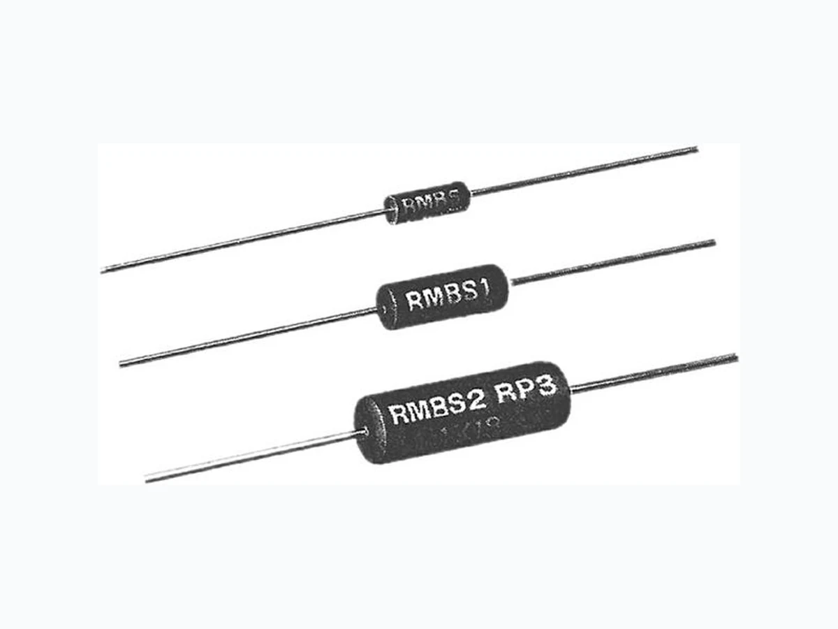
- Material categorization: For definitions of compliance please see www.vishay.com/doc?99912 High stability and low temperature coefficient are the main fe atures of the precision wirewo und resistors type RMB RMBS models just as maintenance parts. Their performances can be compared with those of the best film resistors but they have in addition a greater power rating. RMBS styles meet the more severe requirements of NF C 83-210 (all RMBS styles are approved) and characteristic U of MIL-R-26 E (approxi mate size of RW 70 and 79 resistors) specifications. The two models RMB and RMBS have a similar construction. RMBS are submitted, in a ddition to a process which further increases the stability. On request, non-inductive resistors are available under the reference RMB NI. Note
- Undergoes European Quality Insurance System (CECC) DIMENSIONS in millimeters SERIES AND STYLE A max. Ø B max. E ± 0.1 WEIGHT g RMB0.75 RMBS0.5 7 2.5 0.6 0.3 RMB1.5 RMBS1 10.2 4 0.6 0.7 RMB3 RMBS2 16.2 6.4 0.8 1.5 STANDARD ELECTRICAL SPECIFICATIONS MODEL SIZE RESISTANCE RANGE RATED POWER P25 °C W LIMITING ELEMENT VOLTAGE V TOLERANCE ± % RMB3 300 0.051 to 13K 3 200 0.1, 0.5, 1, 2, 5 RMBS1 10 0.1 to 6.81K 1 120 0.1, 0.5, 1, 2, 5 RMBS2 20 0.015 to 13K 2 200 0.1, 0.5, 1, 2, 5 25 min. 25 min.A Ø BØ E
RMB, RMBS www.vishay.com Vishay Sfernice Revision: 23-Sep-13 2 Document Number: 50010 For technical questions, contact: sferfixedresistors@vishay.com THIS DOCUMENT IS SUBJECT TO CHANGE WITHOUT NOTICE. THE PRODUCTS DESCRIBED HEREIN AND THIS DOCUMENT ARE SUBJECT TO SPECIFIC DISCLAIMERS, SET FORTH AT www.vishay.com/doc?91000 Note
- Undergoes European Quality Insurance System (CECC) TECHNICAL SPECIFICATIONS VISHAY SFERNICE SERIES AND STYLE RMB0.75 RMB1.5 RMB3 RMBS0.5 RMBS1 RMBS2 NF C 83-210 - - - RP1 RP2 RP3 CECC 40201-005 - - - A B C Power Rating at 25 °C 0.75 W 1.5 W 3 W 0.5 W 1 W 2 W Ohmic Range in Relation to Tolerance ± 5 % E24 0.1 to 2 k 0.1 to 6.81 k 0.051 to 13 k 0.1 to 2 k 0.1 to 6.81 k 0.015 to 13 k ± 2 % E48 0.1 to 2 k 0.1 to 6.81 k 0.08 to 12.3 k 0.1 to 2 k 0.1 to 6.81 k 0.078 to 12.4 k ± 1 % E96 0.1 to 2 k 0.1 to 6.81 k 0.1 to 12.4 k 0.1 to 2 k 0.1 to 6.81 k 0.1 to 12.4 k ± 0.5 % E96 0.4 to 2 k 0.4 to 6.81 k 0.3 to 12.4 k 0.4 to 2 k 0.4 to 6.81 k 0.3 to 12.4 k ± 0.1 % Please consult Vishay Sfernice Qualified Ohmic Range NF C 83-210 - - - 1 to 174 1 to 590 1 to 1.3 k Limiting Element Voltage Not applicable 120 V 200 V Not applicable 120 V 200 V Critical Resistance Out of nominal ohmic range PERFORMANCE TESTS CONDITIONS REQUIREMENTS TYPICAL VALUES AND DRIFTS MIL-R-26 E NF C 83-210 RMB RMBS Climatic Sequence NF C 83-210 -55 °C / +200 °C 5 cycles Insulation R > 100 M ± (0.1 % + 0.01 ) > 104 M > 104 M Humidity (Steady State) NF C 83-210 56 days 95 % RH - ± 0.25 % + 0.05 Insulation R > 100 M ± (0.1 % + 0.01 ) > 104 M > 104 M Thermal Shock Load at 100 % P followed by cold temp. exposure at -55 °C Vibration MIL-STD-202 Method 204 - Test D: 20 g 10/2000 Hz Load Life MIL-STD-202 Method 108 Pr 2000 h ± (0.5 % + 0.05 ) ± 0.25 % + 0.05 Moisture Resistance MIL-STD-202 Method 106 ± (0.2 % + 0.05 ) Insulation resistance > 100 M > 103 M > 103 M High Temperature 1000 h at +200 °C ± (0.5 % + 0.05 ) ± 0.5 % + 0.05 Insulation R > 1 G ± 1 % ± 0.3 % Shock MIL-STD-202 TEMPERATURE COEFFICIENT IN THE RANGE -55 °C TO +200 °C OHMIC RANGE REQUIREMENTS NF C 83-210 MIL-R-26E TYPICAL VALUES SFERNICE MIL Rn < 1 ± 100 ppm/°C ± 50 ppm/°C1 Rn < 10 ± 50 ppm/°C Rn 10 ± 25 ppm/°C +0 °C to -20 ppm/°C
RMB, RMBS www.vishay.com Vishay Sfernice Revision: 23-Sep-13 3 Document Number: 50010 For technical questions, contact: sferfixedresistors@vishay.com THIS DOCUMENT IS SUBJECT TO CHANGE WITHOUT NOTICE. THE PRODUCTS DESCRIBED HEREIN AND THIS DOCUMENT ARE SUBJECT TO SPECIFIC DISCLAIMERS, SET FORTH AT www.vishay.com/doc?91000 STABILITY AND POWER RATING Stability changes slightly according to power rating and ambient temperature. This fact is specially important for users needing a life drift lower than the initial resistance tolerance. Typical drifts, after 2000 h life test made under the 90’/30’ conditions and at a 25 °C ambient temperature are: POWER RATING TEMPERATURE RISE MARKING Vishay Sfernice trademark, model, style, CECC style (if applicable) nominal resistance (in ), tolerance (in %), manufacturing date. MODEL STYLE RMBS 0.5 RMBS RMBS
2 R %/R % MODEL
0.75 RMB 1.5 RMB
3 R %/R %
Pn 0.5 W 1 W 2 W 0.15 % Pmax. 1 W 2 W 3.5 W 1 % 1/3 Pn 0.4 W 0.75 W 1.5 W 0.3 % AMBIENT TEMPERATURE IN °C 125 100 0 50 100 150 200 250 275 300 350 RATED POWER IN % RATED POWER IN W 250 200 150 100 0 1 2 3 HOT SPOT TEMPERATURE IN°C RMB0 .75 RMB S0. RMB1.
5 RMBS1
ORDERING INFORMATION
MODEL STYLE OHMIC VALUE TOLERANCE PACKAGING GLOBAL PART NUMBER INFORMATION R M B105300R0JS00 GLOBAL MODEL SIZE OPTION OHMIC VALUE TOLERANCE PACKAGING SPECIAL RMB RMBS RMB: 075 105 300 RMBS: N = Non inductive winding The first four digits are significant figures and the last digit specifies the number of zeros to follow. R designates decimal point. 300R0 = 300 680R0 = 680 20301 = 20.3 k 88R88 = 88.88 ... F = 1 % J = 5 % Standard Packaging: RMB: Size 075 and 105: S14 = Bag, 100 pieces Size 300: S09 = Bag, 50 pieces RMBS: Size 05 and 10: S14 = Bag, 100 pieces Size 20: S09 = Bag, 50 pieces Other packagings available As applicable Ex = MEX
www.vishay.com Vishay Revision: 02-Oct-12 1 Document Number: 91000 Disclaimer ALL PRODUCT, PRODUCT SPECIFICATIONS AND DATA ARE SUBJECT TO CHANGE WITHOUT NOTICE TO IMPROVE RELIABILITY, FUNCTION OR DESIGN OR OTHERWISE. Vishay Intertechnology, Inc., its affiliates, agents, and employee s, and all persons acting on it s or their behalf (collectivel y, “Vishay”), disclaim any and all liability for any errors, inaccuracies or incompleteness contained in any datasheet or in any other disclosure relating to any product. Vishay makes no warranty, repres entation or guarantee regarding the suitabilit y of the products for any particular purpose or the continuing production of any product. To the maximum extent permitted by applicable law, Vishay disclaims (i) any and all liability arising out of the application or use of any product, (ii) any and all liability, including without limitation specia l, consequential or incidental damages, and (iii) any and all i mplied warranties, including warra nties of fitness for particular purpose, non-infringement and merchantability. Statements regarding the suitability of products for certain type s of applications are based on Vishay’s knowledge of typical requirements that are often placed on Vishay products in generic applications. Such statements are not binding statements about the suitability of products for a particular application. It is the customer’s responsib ility to validate that a particu lar product with the properties descri bed in the product specification is suitable fo r use in a particular application. Parameters provided in datasheets and/or specification s may vary in different applications an d performance may vary over time. All operating parameters, including typical pa rameters, must be validated for each customer application by the customer’s technical experts. Product specifications do not expand or otherwise modify Vish ay’s terms and condit ions of purchase, including but not limited to the warranty expressed therein. Except as expressly indicate d in writing, Vishay products are not designed for use in medical, life-saving, or life-sustaining applications or for any other application in which the failure of the Vi shay product could result in personal injury or death. Customers using or selling Vishay products not expressly indicated for use in such applications do so at their own risk. Please contact authorized Vishay personnel to obtain written terms and conditions regarding products designed for such applications. No license, express or implied, by estoppel or otherwise, to any intellectual prope rty rights is granted by this document or by any conduct of Vishay. Product names and markings noted herein may be trademarks of their respective owners. Material Category Policy Vishay Intertechnology, Inc. hereby certi fies that all its products that are id entified as RoHS-Compliant fulfill the definitions and restrictions defined under Directive 2011/65/EU of The Euro pean Parliament and of the Council of June 8, 2011 on the restriction of the use of certain hazardous substances in electrical and electronic equipment (EEE) - recast, unless otherwise specified as non-compliant. Please note that some Vishay documentation may still make reference to RoHS Directive 2002/95/EC. We confirm that all the products identified as being compliant to Directive 2002/95/EC conform to Directive 2011/65/EU. Vishay Intertechnology, Inc. hereby certifies that all its products that are identified as Halogen-Free follow Halogen-Free requirements as per JEDEC JS709A standards. Please note that some Vishay documentation may still make reference to the IEC 61249-2-21 definition. We co nfirm that all the products identified as being compliant to IEC 61249-2-21 conform to JEDEC JS709A standards.