
RL750PT CHENMKO
Document overview
- Manufacturer or author: Provided By www.digicamel.com(FREE DATASHEET DOWNLOAD SITE)
- PDF pages: 2
Technical content
FEATURES
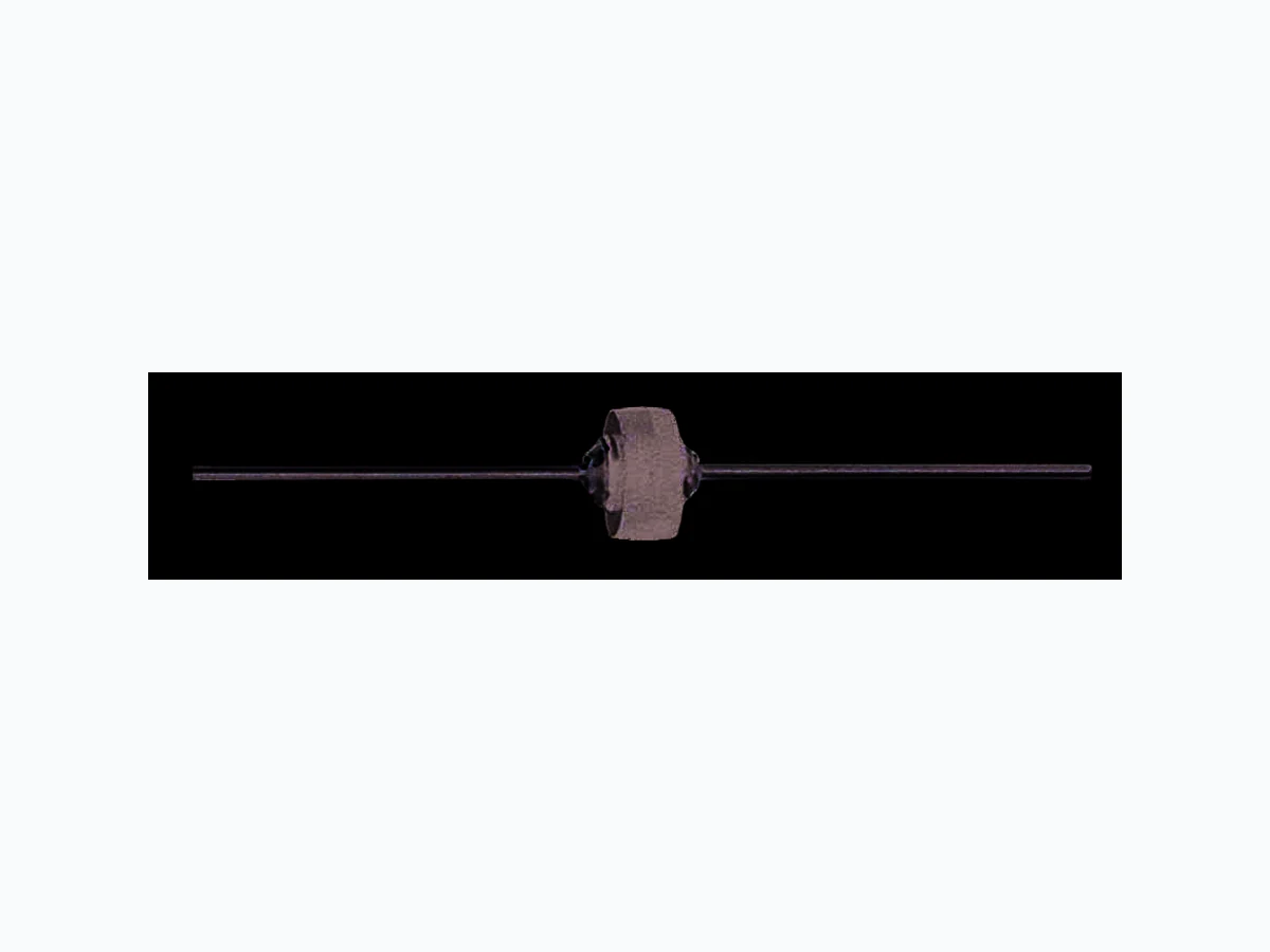
- Plastic package has Underwriters Laboratory Flammability Classification 94V-0 * Low cost * Low leakage * Low forward voltage drop * High current capability * High surge current capabilty MAXIMUM RATINGS AND ELECTRICAL CHARACTERISTICS Ratings at 25oC ambient temperature unless otherwise specified. Single phase, half wave, 60 HZ, resistive or inductive load. For capacitive load, derate current by 20%. RL750PT THRU RL756PT RA-L RA-LDimensions in inches and (millimeters) CHENMKO ENTERPRISE CO.,LTD SILICON RECTIFIER VOLTAGE RANGE 50 - 600 Volts CURRENT 6.0 Amperes ELECTRICAL CHARACTERISTICS ( At TA = 25oC unless otherwise noted ) 2001-6 CHARACTERISTICS SYMBOL UNITS 0.90 1.25 0.025@ TA = 25oC mAmps 1.0 Volts Maximum Instantaneous Forward Voltage at 6.0 A 100 A Maximum Reverse Current at rated DC blocking Voltage per leg MAXIMUM RATINGES ( At TA = 25oC unless otherwise noted ) RATINGS Maximum Recurrent Peak Reverse Voltage Maximum RMS Voltage Maximum DC Blocking Voltage Maximum Average Forward Rectified Current at TA = 60oC P.C. Board Mounting TL = 60oC .125" , (3.18mm) lead lengths Peak Forward Surge Current 8.3 ms single half sine-wave superimposed on rated load (JEDEC method) Operating and Storage Temperature Range SYMBOL VRRM VRMS VDC IO VF IR TJ, TSTG IFSM UNITS Volts Volts Volts Amps RL750PT RL752PT 200 140 200 RL754PT 280 400 400 RL756PT 600 420 600 6.0 400 -65 to +175 Amps Typical Thermal Resistance R JL at 0.5" (12.7mm) lead length R JL 10 oC / W oC RL751PT 100 100 @ TA = 100oC Case: JEDEC RA-L molded plastic Terminals: Plated axial leads, solderable per MIL-STD-750, Method 2026 Polarity: Color band denotes cathode end Mounting Position: Any Weight: 2.50 grams MECHANICAL DATA .410(10.4) .380(9.70) .250(6.4) 1.0(25.4) MIN. 1.0(25.4) MIN. .235(6.0) NOTES : Enough heat sink must be considered in application. RL750PT RL752PT RL754PT RL756PTRL751PT
RATING CHARACTERISTIC CURVES ( RL750PT THRU RL756PT ) FIG. 1 - TYPICAL FORWARD CURRENT DERATING CURVE AVERAGE FORWARD CURRENT, (A) LEAD TEMPERATURE, ( oC ) NUMBER OF CYCLES AT 60 Hz 0 25 50 75 100 150125 175 200 Single Phase Half Wave 60Hz Resistive or Inductive Load FIG. 2 - MAXIMUM NON-REPETIVE FORWARD SURGE CURRENT PEAK FORWARD SURGE CURRENT, ( A ) 1 2 5 10 20 50 100 600 500 400 300 200 100 8.3ms Single Half Sine-Wave (JEDEC Method) FIG. 3 - TYPICAL REVERSE CHARACTERISTICS PER BRIDGE ELEMENT INSTANTANEOUS REVERSE CURRENT, (uA) PERCENT OF RATED PEAK REVERSE VOLTAGE, ( % ) 0 20 40 60 80 100 120 140 .01 1.0 100 TJ =25oC TJ =100oC FIG. 4 - TYPICAL INSTANTANEOUS FORWARD CHARACTERISTICS INSTANTANEOUS FORWARD VOLTAGE, ( V ) INSTANTANEOUS FORWARD CURRENT, ( A ) 100 1.0 0.1 Pulse Width = 300uS 1% Duty Cycle TJ =25oC FIG. 5 - TYPICAL THERMAL RESISTANCE VS LEAD LENGTH THERMAL RESISTANCE ( oC/W ) EQUAL LEAD LENGTH TO HEAT SINK, (IN)