

 Download PDF
CMF_V01 VISHAY
Document overview
- Manufacturer or author: Provided By www.digicamel.com(free datasheet download site)
- PDF pages: 5
Technical content
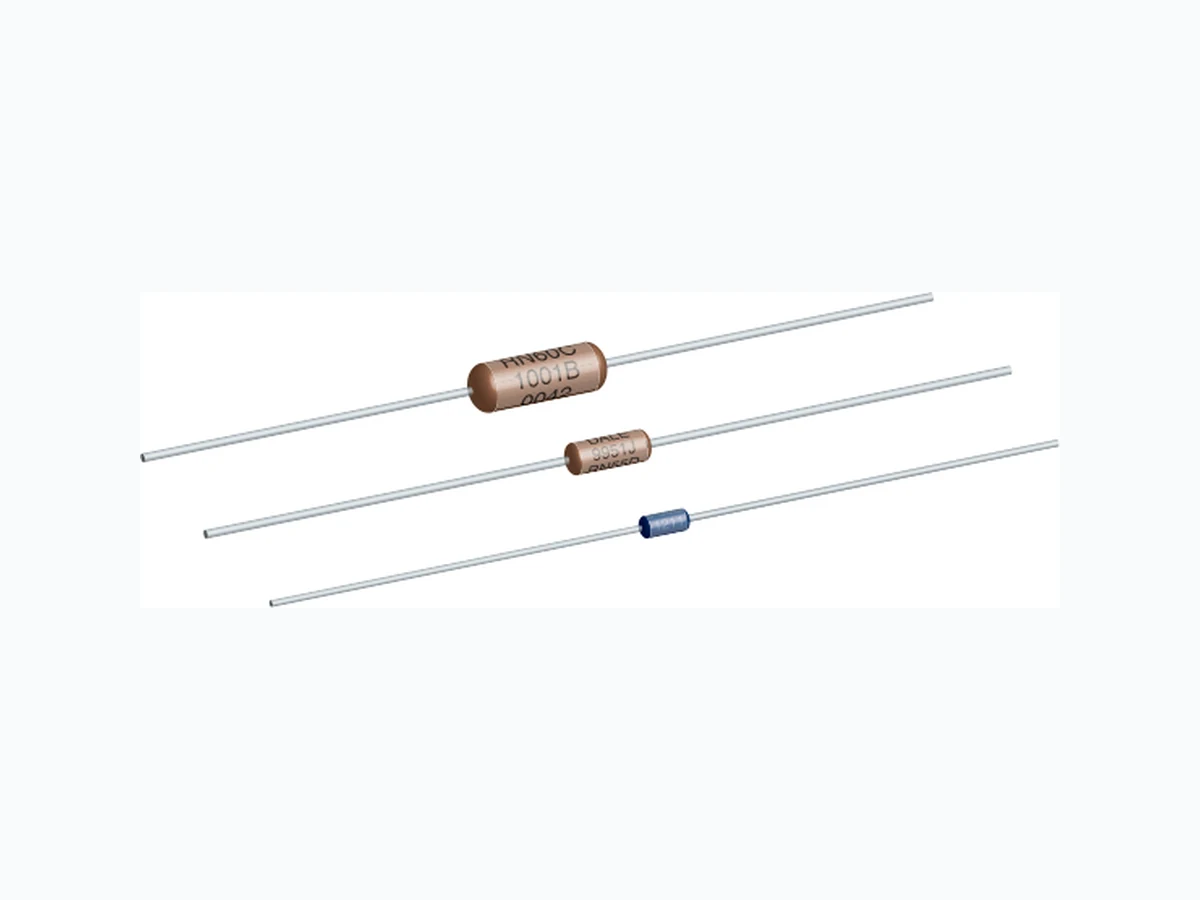
CMF (Military RN and RL) www.vishay.com Vishay Dale Revision: 02-Feb-2022 1 Document Number: 31027 For technical questions, contact: ff2aresistors@vishay.com THIS DOCUMENT IS SUBJECT TO CHANGE WITHOUT NOTICE. THE PRODUCTS DESCRIBED HEREIN AND THIS DOCUMENT ARE SUBJECT TO SPECIFIC DISCLAIMERS, SET FORTH AT www.vishay.com/doc?91000 Metal Film Resistors, Axial, Military, MIL-R-10509 Qualified, Precision, Type RN and MIL-PRF-22684 Qualified, Type RL
FEATURES
- Very low noise (-40 dB)
- Very low voltage coefficient (5 ppm/V)
- Controlled temperature coefficient
- Flame retardant epoxy coating
- Commercial alternatives to military styles are available with higher power ratings. See CMF Industrial data sheet: (www.vishay.com/doc?31018 Notes (1) Continuous working voltage shall be or maximum working voltage, whichever is less. (2) Formerly rated at 1 W and is the direct replacement for RN70 of MIL-R-10509 rev. D. (3) Tolerances of ± 0.1 %, ± 0.25 % and ± 0.5 % are not applicable to characteristic D. STANDARD ELECTRICAL SPECIFICATIONS GLOBAL MODEL MIL STYLE MIL SPEC. SHEET POWER RATING P70 °C W POWER RATING P125 °C W MAX. WORKING VOLTAGE (1) V RESISTANCE RANGE Ω MIL-R-10509 ± 100 ppm/°C (D) RESISTANCE RANGE Ω MIL-R-10509 ± 50 ppm/°C (C) RESISTANCE RANGE Ω MIL-R-10509 ± 25 ppm/°C (E) RESISTANCE RANGE Ω MIL-PRF-22684 TOL. (3) ± % DIELECTRIC STRENGTH VAC CMF50 RN50 08 - 0.05 200 - 10 to 100K 10 to 100K - 0.1, 0.25, 0.5, 1 450 0.5, 1 450 0.5, 1 500 0.5, 1 900 0.5, 1 900 CMF07 RL07 01 0.25 - 250 - - - 51 to 150K 2, 5 450 CMF20 RL20 02 0.50 - 350 - - - 4.3 to 470K 2, 5 700TECHNICAL SPECIFICATIONS PARAMETER UNIT CONDITION Voltage Coefficient ppm/V 5 when measured between 10 % and full rated voltage Insulation Resistance Ω≥ 10 10 min. dry; ≥ 108 min. after moisture test Operating Temperature Range °C -65/+175 (see derating curves for military range) Terminal Strength Ib 5 pound pu ll test for RL07/RL20; 2 pound pull test for all others Solderability Continuous satisfactory coverage when tested in accordance with MIL-R-10509 and MIL-PRF-22684 P x R
CMF (Military RN and RL) www.vishay.com Vishay Dale Revision: 02-Feb-2022 2 Document Number: 31027 For technical questions, contact: ff2aresistors@vishay.com THIS DOCUMENT IS SUBJECT TO CHANGE WITHOUT NOTICE. THE PRODUCTS DESCRIBED HEREIN AND THIS DOCUMENT ARE SUBJECT TO SPECIFIC DISCLAIMERS, SET FORTH AT www.vishay.com/doc?91000 Note
- For additional information on packaging, refer to the Through Hole Resistor Packaging document ( www.vishay.com/doc?31544 APPLICABLE MIL-SPECS MIL-R-10509 and MIL-PRF-22684: The CMF models meet or exceed the electrical, environmental and dimensional requirements of MIL-R-10509 and MIL-PRF-22684. Noise: Vishay Dale metal film re sistors have exceptionally low noise level. Average for standard resistance range is 0.10 μV per V over a decade of frequency, with low and intermediate resistance values typically below 0.05 μV per V. GLOBAL PART NUMBER INFORMATION New Global Part Numbering: RN60D3483FR36 (preferred part numbering format) MIL STYLE CHARACTERISTICS RESISTANCE VALUE TOLERANCE CODE PACKAGING SPECIAL RN50 RN55 RN60 RN65 RN70 E = 25 ppm C = 50 ppm D = 100 ppm 3 digit significant figure, followed by a multiplier. Use “R” for values < 100 Ω 10R0 = 10 Ω 2152 = 21.5 kΩ 2494 = 2.49 MΩ B = ± 0.1 % C = ± 0.25 % D = ± 0.5 % F = ± 1 % B14 = tin / lead, bulk BSL = tin / lead, bulk, single lot date code R36 = tin / lead, T/R (full) RE6 = tin / lead, T/R (1000 pieces) RSL = tin / lead, T/R, single lot date code Blank = standard (Dash number) 88 = hot solder dip 143 = non-magnetic Historical Part Number Example: RN60D3483F (will continue to be accepted) RN60 D 3483 F R36 MIL STYLE CHARACTERISTIC RESISTANCE VALUE TOLERANCE CODE PACKAGING New Global Part Numbering: RL07S471JR36 (preferred part numbering format) MIL STYLE LEAD MATERIAL RESISTANCE VALUE TOLERANCE CODE PACKAGING SPECIAL RL07 RL20 S = solderable 2 digit significant figure, followed by a multiplier. Use “R” for values < 10 Ω 4R3 = 4.3 Ω 202 = 2.0 kΩ 474 = 470 kΩ G = ± 2 % J = ± 5 % B14 = tin / lead, bulk BSL = tin / lead, bulk, single lot date code R36 = tin / lead, T/R (full) RE6 = tin / lead, T/R (1000 pieces) RSL = tin / lead, T/R, single lot date code Blank = standard (Dash number) 88 = hot solder dip 143 = non-magnetic Historical Part Number Example: RL07S471J (will continue to be accepted) RL07 S 471 J R36 MIL STYLE LEAD MATERIAL RESISTANCE VALUE TOLERANCE CODE PACKAGING MATERIAL SPECIFICATIONS Element Nickel-chrome alloy Coating Flame retardant epoxy, formulated for superior moisture protection Core Fire-cleaned high purity ceramic Termination Standard lead material is solder-coated copper. Solderable and weldable. CAGE CODE: 91637 ENVIRONMENTAL SPECIFICATIONS General Environmental performance is shown in the Environmental Performance table. Test methods are those specified in MIL-R-10509 and MIL-PRF-22684. Shelf Life Resistance shifts due to storage at room temperature are negligible. 6D 8 3 F3NR 4R 630 0S 1 J R6LR 7347
CMF (Military RN and RL) www.vishay.com Vishay Dale Revision: 02-Feb-2022 3 Document Number: 31027 For technical questions, contact: ff2aresistors@vishay.com THIS DOCUMENT IS SUBJECT TO CHANGE WITHOUT NOTICE. THE PRODUCTS DESCRIBED HEREIN AND THIS DOCUMENT ARE SUBJECT TO SPECIFIC DISCLAIMERS, SET FORTH AT www.vishay.com/doc?91000 Vishay Dale CMF resistors have an operating temperature range of -65 °C to +175 °C. They must be derated according to the following curves: DIMENSIONS in inches (millimeters) Note (1) Lead length for product in bulk pack. For product supplied in tape and re el, the actual lead length would be based on the body size, tape spacing and lead trim Notes
- Commercial equivalents of military styles are avai lable with higher power ratings. Consult factory (1) Formerly rated at 1 W and is the direct replacement for RN70 of MIL-R-10509 rev. D VISHAY DALE MODEL AB C (MAX.) D CMF50 0.150 ± 0.020 (3.81 ± 0.51) 0.065 ± 0.015 (1.65 ± 0.38) 0.244 (6.20) 0.016 ± 0.002 (0.41 ± 0.05) CMF55 0.240 ± 0.020 (6.10 ± 0.51) 0.090 ± 0.008 (2.29 ± 0.20) 0.290 (7.37) 0.025 ± 0.002 (0.64 ± 0.05) CMF60 0.344 ± 0.031 (8.74 ± 0.79) 0.145 ± 0.015 (3.68 ± 0.38) 0.425 (10.80) 0.025 ± 0.002 (0.64 ± 0.05) CMF65 0.562 ± 0.031 (14.27 ± 0.79) 0.180 ± 0.015 (4.57 ± 0.38) 0.687 (17.45) 0.025 ± 0.002 (0.64 ± 0.05) CMF70 0.562 ± 0.031 (14.27 ± 0.79) 0.180 ± 0.015 (4.57 ± 0.38) 0.687 (17.45) 0.032 ± 0.002 (0.81 ± 0.05) CMF07 0.240 ± 0.020 (6.10 ± 0.51) 0.090 ± 0.008 (2.29 ± 0.20) 0.290 (7.37) 0.025 ± 0.002 (0.64 ± 0.05) CMF20 0.375± 0.040 (9.53 ± 1.02) 0.145 ± 0.015 (3.68 ± 0.38) 0.425 (10.80) 0.032 ± 0.002 (0.81 ± 0.05) MILITARY POWER RATING WATTAGE MILITARY QUALIFIED MIL-R-10509 MIL-PRF-22684 AT +70 °C (D) AT +125 °C (C and E) AT +70 °C 0.05 - RN50 - 0.10 - RN55 -
0.125 RN55 RN60 -
0.25 RN60 RN65 RL07
0.50 RN65 RN70 RL20
0.75 (1) RN70 - - RE WOP DETAR FO AMBIENT TEMPERATURE °C 120 100 MIL-R-10509 Char. C and E Rating MIL-R-10509 Char. D Rating MIL-PRF-22684 DERATING 170150130110907050 A B DC (Max.) 1.50 ± 0.125 (1) (38.10 ± 3.18)
CMF (Military RN and RL) www.vishay.com Vishay Dale Revision: 02-Feb-2022 4 Document Number: 31027 For technical questions, contact: ff2aresistors@vishay.com THIS DOCUMENT IS SUBJECT TO CHANGE WITHOUT NOTICE. THE PRODUCTS DESCRIBED HEREIN AND THIS DOCUMENT ARE SUBJECT TO SPECIFIC DISCLAIMERS, SET FORTH AT www.vishay.com/doc?91000 Note
- RL series ar e color banded per MIL-PRF-22684. MARKING (per MIL-PRF-10509) Characteristics: D = 100 ppm, C = 50 ppm, E = 25 ppm Tolerance: F = 1 %, D = 0.5 %, C = 0.25 %, B = 0.1 % Value = Three significant figures and multiplier J = JAN (Joint Army - Navy) brand RN50: (3 lines) RN55, RN60, RN65, RN70 (4 lines) J50D 1211 F137 JAN, type, characteristic Value Tolerance and 3 digit date code DALE 0137J RN55D 1211F Company logo 4 digit date code and JAN brand Type and characteristic Value and Tolerance PERFORMANCE REQUIREMENT MIL-R-10509 MIL-PRF-22684 CHARACTERISTIC D CHARACTERISTIC C CHARACTERISTIC E MIL Temperature Coefficient +200 ppm/°C -500 ppm/°C ± 50 ppm/°C ± 25 ppm/°C ± 200 ppm/°C Applicable Vishay Dale Temperature Coefficient ± 100 ppm/°C ± 50 ppm/°C ± 25 ppm/°C ± 200 ppm/°C TEST MIL max. MILmax. MILmax. MILmax. Thermal Shock ± 0.50 % ΔR ± 0.25 % ΔR ± 0.25 % ΔR ± 1.00 % ΔR Short Time Overload ± 0.50 % ΔR ± 0.25 % ΔR ± 0.25 % ΔR ± 0.50 % ΔR Low Temperature Operation ± 0.50 % ΔR ± 0.25 % ΔR ± 0.25 % ΔR ± 0.50 % ΔR Moisture Resistance ± 1.50 % ΔR ± 0.50 % ΔR ± 0.50 % ΔR ± 1.50 % ΔR Shock ± 0.50 % ΔR ± 0.25 % ΔR ± 0.25 % ΔR ± 0.50 % ΔR Vibration ± 0.50 % ΔR ± 0.25 % ΔR ± 0.25 % ΔR ± 0.50 % ΔR Load Life ± 1.00 % ΔR ± 0.50 % ΔR ± 0.50 % ΔR ± 2.00 % ΔR Dielectric Withstanding Voltage ± 0.50 % ΔR ± 0.25 % ΔR ± 0.25 % ΔR ± 0.50 % ΔR Effect of Solder ± 0.50 % ΔR THERMAL RESISTANCE 100 120 APPLIED POWER IN W HEAT RISE (°C ABOVE AMBIENT) CMF65, CMF70 CMF50 CMF55 CMF60 CMF20 CMF07
www.vishay.com Vishay Revision: 01-Jul-2024 1 Document Number: 91000 THIS DOCUMENT IS SUBJECT TO CHANGE WITHOUT NOTICE. THE PRODUCTS DESCRIBED HEREIN AND THIS DOCUMENT ARE SUBJECT TO SPECIFIC DISCLAIMERS, SET FORTH AT www.vishay.com/doc?91000 Disclaimer ALL PRODUCT, PRODUCT SPECIFICATIONS AND DATA AR E SUBJECT TO CHANGE WITH OUT NOTICE TO IMPROVE RELIABILITY, FUNCTION OR DESIGN OR OTHERWISE. Vishay Intertechnology, Inc., its affiliates, agents, and employee s, and all persons acting on it s or their behalf (collectivel y, “Vishay”), disclaim any and all liability for any errors, inaccuracies or incompleteness contained in any datasheet or in any other disclosure relating to any product. Vishay makes no warranty, representation or guarantee regarding the suitability of the products for any particular purpose or the continuing production of any product. To the maximum extent permitted by applicable law, Vishay disclaims (i) any and all liability arising out of the application or use of any product , (ii) any and all liability, including without limitation specia l, consequential or incidental damages, and (iii) any and all implied warranties, incl uding warranties of fitness for particular purpose, non-infringement and merchantability. Statements regarding the suitability of pro ducts for certain types of applications are based on Vishay's knowledge of typical requirements that are often placed on Vishay products in ge neric applications. Such statements are not binding statements about the suitability of products for a particular application. It is the customer's responsibility to validate that a particular product with the properties described in the product specification is suitable for use in a particular application. Parameters provided in datasheets and / or specificat ions may vary in different applications and performance may vary over time. All operating parameters, including typical parameters, must be validated for each customer application by the customer's technical experts. Product specifications do not expand or otherwise modify Vishay's terms and conditions of purchase, including but not limited to the warranty expressed therein. Hyperlinks included in this datasheet may direct users to third-party websites. These links are provided as a convenience and for informational purposes only. Inclusion of these hyperlinks does not constitute an endorsement or an approval by Vishay of any of the products, services or opinions of the corporation, organization or individual associated with the third-party website. Vishay disclaims any and all liability and bears no responsibility for the accuracy, legality or content of the third-party web site or for that of subsequent links. Vishay products are not designed for use in life-saving or life -sustaining applications or any application in which the failure of the Vishay product could result in personal injury or death unless specifically qualified in writing by Vishay. Customers using or selling Vishay products not expressly indicated for use in such applications do so at their own risk. Please contact authorized Vishay personnel to obtain written terms and conditions regarding products designed for such applications. No license, express or implied, by estoppel or otherwise, to any intellectual property rights is granted by this document or by any conduct of Vishay. Product names and markings noted herein may be trademarks of their respective owners. © 2024 VISHAY INTERTECHNOLOGY, INC. ALL RIGHTS RESERVED