

 Download PDF
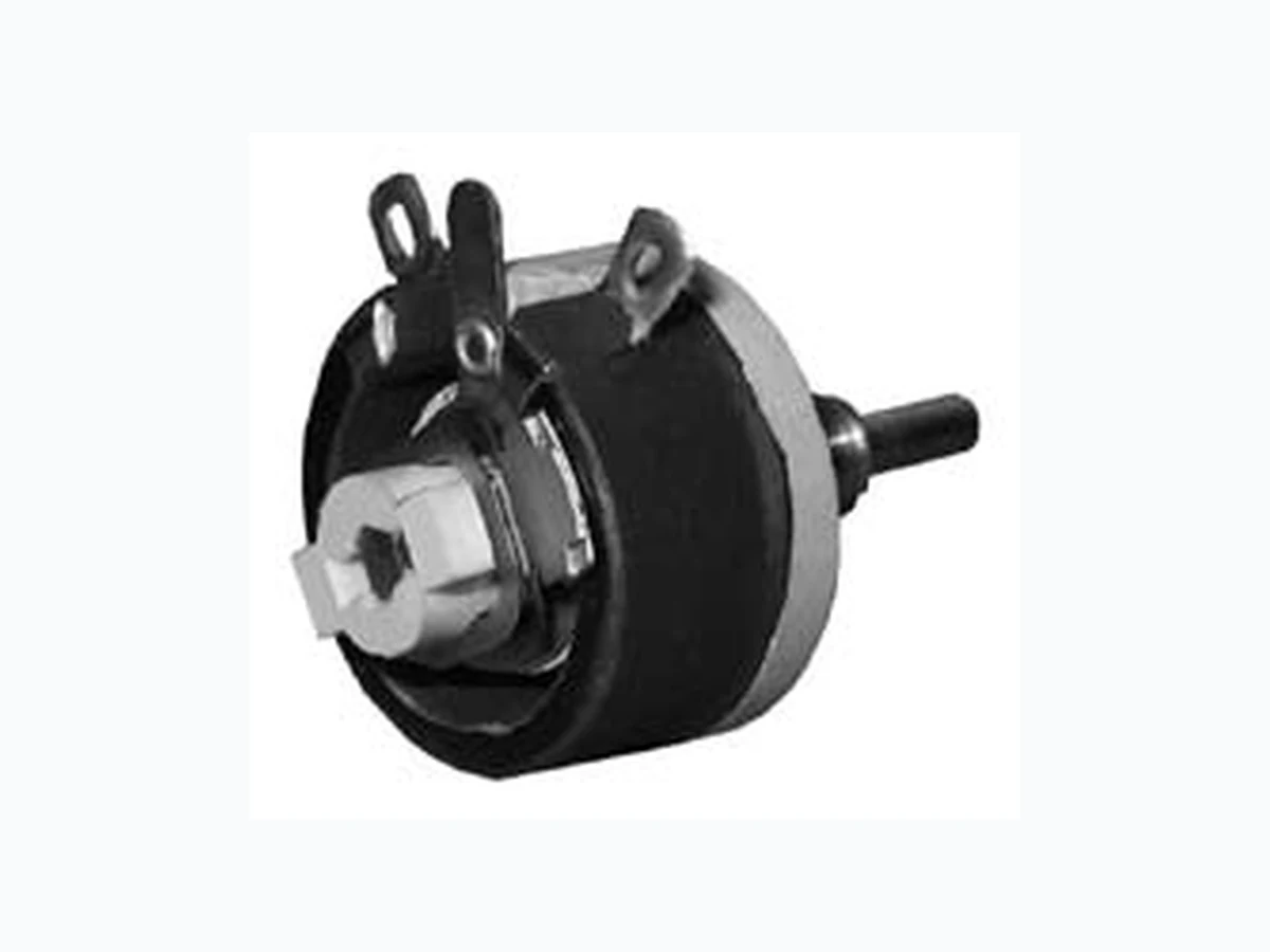
RHS100E OHMITE
Document overview
- PDF pages: 3
Technical content
Page 1
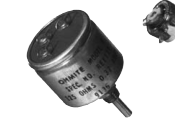
M o d e l C Max. Voltage Behind panel “B" Diameter “D"
Ohmic
Model Type Watts range Core (RMS)\* (in./mm Ref.) C RCS/RCL 7.5 10.0-5K enclosed 305 0.875/22.23
- See Catalog #203 for complete details.
0.531" 13.49 mm
Mounting: Panels
0.25"
to 0.125" (3.18mm)
6.4 mm
thick with 1/4-32
Dimension “C" Shaft Rotation
(in./mm Ref.) (in./mm Ref.) torque
(±5°)
0.515/ 13.08
— 0.25-3 oz. in. 300°
Locking
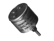
shaft
B
| 0.625" 15.88 mm D 0.125" 3.18 mm 0.25" 0.25" | B 0.625" 15.88 mm |
| St sh 0.109" |
bushing and hex nut (1/16" thick).
Standard shaft
6.4 mm
6.4 mm
2.78 mm
M o d e l E Max. Voltage Behind panel “B" Diameter “D"
Ohmic
Model Type Watts range Core (RMS)\* (in./mm Ref.) E RES/REL 12.5 1.0-15K open 305 0.688/17.46 E REE 12.5 1.0-15K enclosed 305 1.219/30.96
- See Catalog #203 for complete details.
unenclosed 0.625" 15.88 mm
Dimension “C" Shaft Rotation
(in./mm Ref.) (in./mm Ref.) torque
(±5°)
0.875/ 22.23 0.594/15.08 1-6 oz. in.
300°
1.047/ 26.59
— 1-6 oz. in.
300°
0.531" shaft 13.49 mm locking
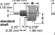
D
nut
0.25" 6.35 mm
REL locking shaft 0.406"
Mounting: Panels to
10.32 mm
0.125" (3.18mm) thick
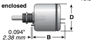
with 1/4-32 bushing and hex nut (1/16" thick).
Dimensions for reference only; consult factory for details. Since all rheostats/potentiometers are electro-mechanical devices, they are subject to mechanical wear and, therefore, have a finite life. Models H, J, K, L and N are listed under UL File No. E-10946 and CSA File No. 21309 unless noted otherwise. All rheostats are 10% tolerance.
Page 2
M o d e l s H , J , G , K , L Max. Voltage Behind panel “B" Diameter “D"
Ohmic
Model Type Watts range Core (RMS)\* (in./mm Ref.) H RHS/RHL 25 1.0-25K open 500 1.375/34.93 J RJS 50 0.5-50K open 750 1.375/34.93 G RGS 75 0.5-50K open 900 1.750/44.45 K RKS 100 0.5-50K open 1000 1.750/44.45 L RLS 150 0.5-50K open 1200 2.000 / 50.8
- Models H, J, G, and K also available in enclosed versions.
- See Catalog #203 for complete details.
0.375"
1.75"
9.53 mm
Dimension “C" Shaft Rotation
(in./mm Ref.) (in./mm Ref.) torque
(±5°)
1.560/ 39.62 0.940/23.88 0.25-0.5 lb. in. 300° 2.31 / 58.67 1.56 /39.62 0.25-2 lb. in. 300° 2.75 / 69.25 1.78 /45.21 0.5-2 lb. in. 300° 3.125/ 79.38 1.91 /48.51 0.5-2 lb. in. 300° 4.00 /101.60 2.28 /57.91 0.5-3 lb. in. 300°
0.75" 19.05 mm
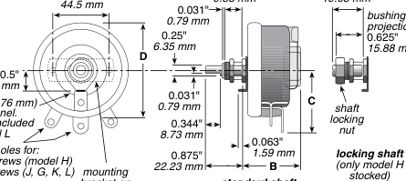
Mounting: Panels to 0.25" (6.35mm) thick with 3/8-32 bushing and hex nut
12.7 mm
(3/32" thick) (or with 10-32
drill 0.188" (4.76 mm)
x 0.75 flat-head screws
hole in panel.
for model L only).
washer not included in model L
no. 2 screws (model H)
standard shaft
bracket on model L only
(models H, J, G, K, L)
M o d e l s P, N , R , U Max. Voltage Behind panel “B" Diameter “D"
Ohmic
Model Type Watts range Core (RMS)\* (in./mm Ref.) P RPS 225 1.0-30K open 1300 2.125/53.98 N RNS 300 1.0-50K open 1225 2.375/60.33 R RRS 500 1.0-20K open 1450 2.125/53.98 U RUS 1000 1.0-20K open 1600 3.000 / 76.2
- See Catalog #203 for complete details.
M M
Dimension “C" Shaft Rotation
(in./mm Ref.) (in./mm Ref.) torque
(±5°)
5.00 /127.00 2.97 /75.44 2.5-4 lb. in. 310° 6.00 /152.40 3.44 /87.38 2.5-5 lb. in. 320° 8.00 /203.20 4.31/109.47 4.5-7 lb. in. 325° 12.00 /304.80 6.38/162.05 3.5-7 lb. in. 335°
2" 51 mm B
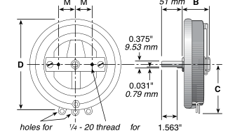
Dimension “M" P 0.875" 22.23 mm N 1.188" 30.16 mm R 1.5" 38.1 mm U 3" 76.2 mm Mounting: Panels to 1.25" (31.75mm) thick with 1/4-20 flat-head screws.
mounting screws 39.7 mm
no. 8 screws
(continued)
Page 3
o r d e r i n g i n f o r m at i o n
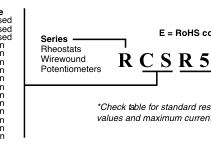
Code Watts Model Shaft
Core
CL = 7.5 C Locking Enclosed CS = 7.5 C Standard Enclosed EE = 12.5 E Standard Enclosed EL = 12.5 E Locking Open ES = 12.5 E Standard Open GS= 75 G Standard Open HL = 25 H Locking Open HS = 25 H Standard Open JS = 50 J Standard Open KS = 100 K Standard Open LS = 150 L Standard Open NS = 300 N Standard Open PS = 225 P Standard Open RS = 500 R Standard Open US = 1000 U Standard Open
Resistance Value\*
E = RoHS compliant
Example:
- RoHS compliant product available. Add
R50 = 0.50Ω
“E" suffix to part number to specify.
1R0 = 1Ω 7R5 = 7.5Ω
- Made-to-order rheostats available:
250 = 250Ω
Contact nearest Ohmite sales office.
1K0 = 1,000Ω
\* Voltage rating dependent on resistance
1K75 = 1,750Ω 4K5 = 4,500Ω
value.
50K = 50,000Ω
| value Part No. Prefix Ohmic Suffix | 7.5W Model C shaft Locking Std. max. RCS––– RCL––– Amps | 12.5W Model E shaft Locking Enclosed Std. max. RES––– REL––– REE––– Amps | 25W Model H shaft Locking Std. max. RHS––– RHL––– Amps | 50W Model J max. RJS––– Amps | 75W Model G max. RGS––– Amps | 100W Model K max. RKS––– Amps | 150W Model L max. RLS––– Amps | 225W Model P max. RPS––– Amps | 300W Model N max. RNS––– Amps | 500W Model R max. RRS––– Amps | 1000W Model U max. RUS––– Amps |
|---|---|---|---|---|---|---|---|---|---|---|---|
| 0.5 –––R50 1 –––1R0 1.5 –––1R5 2 –––2R0 2.5 –––2R5 | 3.53 2.50 2.24 | 5.00 3.54 | 10.0 7.07 5.00 | 12.3 8.66 6.12 | 14.1 10 7.07 | 17.3 12.3 8.65 | 15.0 10.6 | 17.32 12.24 | 22.3 18.2 15.8 14.1 | 31.6 25.8 22.4 20.0 | |
| 3 –––3R0 4 –––4R0 5 –––5R0 6 –––6R0 7.5 –––7R5 | 2.04 1.58 1.44 | 2.88 2.04 | 3.53 2.88 | 5.00 3.88 3.16 | 5.75 4.47 3.65 | 7.07 5.48 4.47 | 8.66 7.50 6.71 5.49 | 10.00 8.66 7.75 6.32 | 12.9 11.2 10.0 | 18.3 15.8 14.1 | |
| 8 –––8R0 10 –––10R 12 –––12R 12.5 –––12R5 15 –––15R | 0.86 0.71 | 1.25 1.12 0.91 | 1.77 1.58 1.29 | 2.50 2.04 | 2.74 | 3.16 | 3.88 3.163 | 4.74 3.87 | 5.48 4.47 | 7.90 6.30 | 11.2 10.0 8.95 |
| 16 –––16R 22 –––22R 25 –––25R 35 –––35R 40 –––40R | 0.55 0.46 | 0.71 0.60 | 1.00 0.845 | 1.76 1.50 1.19 | 2.17 1.73 | 2.50 2.0 | 2.450 2.070 | 3.00 | 3.46 | 5.60 4.47 3.54 | 7.90 6.33 |
| 50 –––50R 75 –––75R 80 –––80R 100 –––100 125 –––125 | 0.39 0.32 0.27 | 0.50 0.40 0.36 0.32 | 0.707 0.575 0.500 0.445 | 1.00 0.790 0.630 | 1.23 1.00 0.866 | 1.41 1.15 1.00 | 1.735 1.415 1.225 | 2.12 1.73 1.50 | 2.45 2.00 1.73 | 3.16 2.52 2.00 | 4.47 3.65 3.16 |
| 150 –––150 160 –––160 175 –––175 200 –––200 225 –––225 | 0.22 0.19 | 0.29 0.27 0.25 | 0.375 | 0.575 0.470 | 0.612 | 0.707 | 1.000 0.865 | 1.22 1.06 | 1.41 1.22 | 1.69 | 2.39 2.11 |
| 250 –––250 300 –––300 325 –––325 350 –––350 400 –––400 | 0.17 0.15 | 0.22 0.19 | 0.316 0.267 | 0.408 | 0.500 0.433 | 0.575 0.500 | 0.775 0.655 | 0.866 0.750 | 1.00 0.866 | 1.41 1.24 | 1.83 1.48 |
| 500 –––500 600 –––600 700 –––700 750 –––750 800 –––800 | 0.12 0.10 | 0.16 0.13 | 0.222 0.182 | 0.316 0.250 | 0.388 0.316 | 0.447 0.365 | 0.548 0.447 | 0.567 | 0.655 | 1.00 0.817 | 1.41 1.15 |
| 900 –––900 1000 –––1K0 1200 –––1K2 1250 –––1K25 1500 –––1K5 | 0.086 0.071 | 0.10 0.090 | 0.155 0.129 | 0.224 | 0.274 0.224 | 0.316 0.258 | 0.346 | 0.500 0.433 0.387 | 0.578 0.500 0.447 | 0.707 0.577 | 1.00 0.816 |
| 1600 –––1K6 1750 –––1K75 1800 –––1K8 2000 –––2K0 2250 –––2K25 | 0.176 | 0.194 | 0.224 | 0.288 0.259 | 0.358 0.336 | 0.414 0.387 | 0.500 | ||||
| 2500 –––2K5 3000 –––3K0 3500 –––3K5 4500 –––4K5 5000 –––5K0 | 0.055 0.046 0.039 | 0.070 0.060 0.050 | 0.100 0.084 0.070 | 0.141 0.119 0.100 | 0.173 0.123 | 0.200 0.141 | 0.224 0.182 | 0.300 0.346 0.447 0.633 = Standard values; check availability R he ostats ar e s ilicone-ce ram ic coate d at and a bo ve the fo llow ing ohm ic v alues: M od el C: all M od el G: 500 0Ω M od el E: 75 0Ω M od el K: 500 0Ω M od el H: 20 00Ω M od el L: 750 0Ω M od el J: 500 0Ω | |||
| 7500 –––7K5 8000 –––8K0 10000 –––10K 12500 –––12K5 15000 –––15K | 0.041 0.035 0.031 0.029 | 0.058 0.050 0.041 | 0.079 0.070 0.058 | 0.100 0.087 | 0.115 0.100 | 0.141 0.122 | |||||
| 20000 –––20K 25000 –––25K 30000 –––30K 40000 –––40K 50000 –––50K | 0.035 0.032 | 0.050 0.045 0.041 0.035 0.032 | |||||||||