
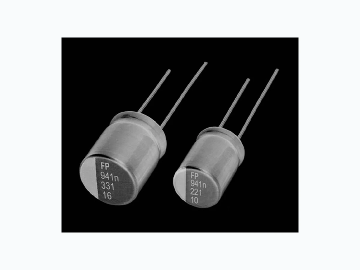

 Download PDF
RHT NICHICON
Document overview
- PDF pages: 2
Technical content
Page 1
| CONDUCTIVE POLYMER ALUMINUM SOLID EL | ECTROLYTIC CAPACITORS |
|---|---|
| RHT High Temperature(125°C) Low ESR, High Capacitance, High ripple current. Load life of 1000 hours at 125°C. Radial lead type : Lead free flow soldering condition correspondence. Compliant to the RoHS directive (2011/65/EU). | |
Specifications
| Item | Performance Characteristics | |
| Category Temperature Range | –55 to +125°C | |
| Rated Voltage Range | 6.3 to 35V | |
| Rated Capacitance Range | 100 to 1000µF | |
| Capacitance Tolerance | ±20% at 120Hz, 20°C | |
| Tangent of loss angle (tan δ) | Less than or equal to the specified value at 120Hz, 20°C | |
| ESR ( 1) | Less than or equal to the specified value at 100kHz, 20°C | |
| Leakage Current ( 2) | Less than or equal to the specified value. After 2 minutes' application of rated voltage at 20°C | |
| Endurance | Test condition 125°C, rated voltag | e 1000Hrs. |
| Capacitance change Within ±20% of initi | al value before test | |
| tan δ 200% or less than t | he initial specified value | |
| ESR( 1) 200% or less than t | he initial specified value | |
| Leakage current ( 2) Less than or equal t | o the initial specified value | |
1 ESR should be measured at both of the terminal ends closest to the capacitor body. 2 Conditioning : If any doubt arises, measure the leakage current after the voltage treatment of applying DC rated voltage continuously to the capacitor for 120 minutes at 105°C.
Dimensions
Aluminum case
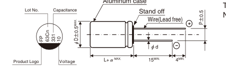
(mm)
| φD×L | φd | P |
| 8×11.5 | 0.6 | 3.5 |
| 10×12.5 | 0.6 | 5.0 |
α 1.5 1.5
Frequency coefficient of rated ripple current
| Frequency | 120 Hz | 1 kHz | 10 kHz |
| Coefficient | 0.10 | 0.45 | 0.50 |
100 kHz 300 kHz 1.00 1.00
Dimension table in next page.
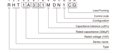
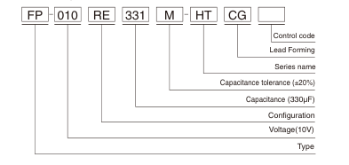
Type numbering system (Example : 10V 330µF) Nichicon part number
1 2 3 4 5 6 7 8 9 10 11 12 13 14
FPCAP part number
CAT.8100H
Page 2
CONDUCTIVE POLYMER ALUMINUM SOLID ELECTROLYTIC CAPACITORS
RHT
Dimensions
| Rated Voltage (V) (code) | Surge Voltage (V) | Rated Capacitance (µF) | Case Size φD×L (mm) | tan δ | Leakage Current (µA, 2min.) | ESR Ra (mΩ) (m (20°C/100kHz) | ted Ripple Current Arms)(105°C/100kHz) | NICHICON | FPCAP | |
|---|---|---|---|---|---|---|---|---|---|---|
| 6.3 (0J) | 7.2 | 680 | 10×12.5 | 0.12 | 857 | 12 | 5450 | 1740 | RHT0J681MDN1□□ | FP-6R3RE681M-HT□□ |
| 820 | 10×12.5 | 0.12 | 1033 | 12 | 5450 | 1740 | RHT0J821MDN1□□ | FP-6R3RE821M-HT□□ | ||
| 1000 | 8×11.5 | 0.12 | 1260 | 10 | 5200 | 1600 | RHT0J102MDN1□□ | FP-6R3RE102M-HT□□ | ||
| 10 (1A) | 11.5 | 220 | 8×11.5 | 0.12 | 440 | 17 | 3950 | 1260 | RHT1A221MDN1□□ | FP-010RE221M-HT□□ |
| 330 | 8×11.5 | 0.12 | 660 | 17 | 3950 | 1260 | RHT1A331MDN1□□ | FP-010RE331M-HT□□ | ||
| 390 | 8×11.5 | 0.12 | 780 | 16 | 3950 | 1260 | RHT1A391MDN1□□ | FP-010RE391M-HT□□ | ||
| 560 | 10×12.5 | 0.12 | 1120 | 13 | 5250 | 1680 | RHT1A561MDN1□□ | FP-010RE561M-HT□□ | ||
| 16 (1C) | 18.4 | 270 | 10×12.5 | 0.12 | 864 | 16 | 4750 | 1520 | RHT1C271MDN1□□ | FP-016RE271M-HT□□ |
| 330 | 10×12.5 | 0.12 | 1056 | 16 | 4750 | 1520 | RHT1C331MDN1□□ | FP-016RE331M-HT□□ | ||
| 470 | 10×12.5 | 0.12 | 1504 | 16 | 4750 | 1520 | RHT1C471MDN1□□ | FP-016RE471M-HT□□ | ||
| 20 (1D) | 23.0 | 150 | 10×12.5 | 0.12 | 600 | 20 | 4350 | 1390 | RHT1D151MDN1□□ | FP-020RE151M-HT□□ |
| 35 (1V) | 40.2 | 100 | 10×12.5 | 0.12 | 700 | 25 | 3250 | 1040 | RHT1V101MDN1□□ | FP-035RE101M-HT□□ |
: At ambient temperature
Frequency Characteristics (The frequency characteristics are typical and not a guaranteed value.)
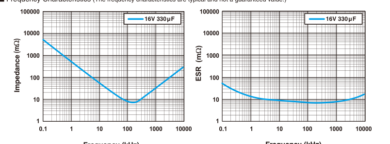
Frequency (kHz)
Frequency (kHz)
Taping specifications are given in page 26, 27. Please refer to page 3 for the minimum order quantity.