
RHF1009A.fm
Document overview
- Manufacturer or author: STMICROELECTRONICS
- PDF pages: 19
Technical content
Datasheet sections
- 1 Absolute maximum ratings and operating conditions
- 2 Electrical characteristics
- 3 Radiation
- 4 Design information
- 4.1 Introduction
- 4.2 Average temperature coefficient
- 4.3 Minimum and maximum cathode current
- 4.3.1 Minimum operating cathode current
- 4.4 Capacitive load considerations
- 5 Package information
- 5.1 Ceramic Flat-10 package information
- 6 Ordering information
- 7 Other information
- 7.1 Date code
- 7.2 Product documentation
- 8 Revision history
Features
- Adjustable shunt, 2.5 V to 5.5 V
- High precision ±0.2% at 2.5 V at 25 °C
- Wide operating current: 60 µA to 12 mA
- 30 ppm/°C maximum temperature range at 2.5 V
- Stable on capacitive load
- ELDRS-free up to 300 krad
- 300 krad high/low dose rate
- SEL-free up to 120 MeV.cm²/mg
- SET characterized
- Mass = 0.50 g
- SMD: 5962F14222
Applications
- Space systems
- Space data acquisition systems
- Aerospace instrumentation
- ADC references
Description
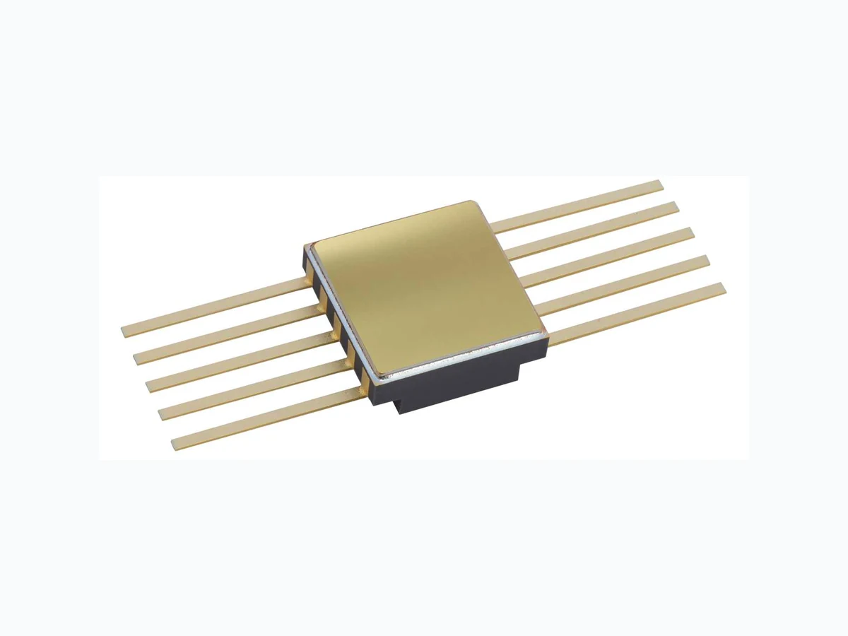
The RHF1009A is a low-power adjustable 2.5 V voltage reference, specifically designed to sustain radiations in space applications. Mounted in a Flat-10 ceramic package, the RHF1009A uses a dedicated architecture and design rules to provide the best immunity against heavy-ions. A very low operating current and very good stability over a wide temperature range of -55 °C to +125 °C make the RHF1009A particularly suitable for precision and power saving. Ceramic Flat-10 The upper metallic lid is not electrically connected to any pins, nor to the IC die inside the package Pin connections (top view) NC NC NC A NC NC NC K VRef NC
1 Absolute maximum ratings and operating conditions
Table 1. Absolute maximum ratings
- Human body model: a 100 pF capacitor is charged to the specified voltage, t hen discharged through a
while the other pins are left floating. connected pin combinations while the other pins are left floating.
- Charged device model: all pins and package are ch arged together to the specified voltage and then
discharged directly to ground through only one pin. Table 2. Operating conditions
2 Electrical characteristics
Parameters tested before radiation are shown in Table 3. Table 3. Anode is connected to Gnd (0 V), V K is in reference to anode voltage. C K (between anode
- Reliability verified with a cathode current setti ng I K = 10 mA
3 Radiation
MIL-STD-883 TM 1019 specification.
- All tests are performed in accordance with MIL-PRF-38535 and the test method 1019 of MIL-STD-883 for total ionizing dose (TID).
- The ELDRS characterization is performed in qualification only on both biased and unbiased parts, on a sample of ten units from two different wafer lots.
- Each wafer lot is tested at high-dose rate only, in the worst bias case condition, based on the results obtained during the initial qualification. Heavy-ions The behavior of the product when submitted to heavy-ions is not tested in production. Heavy- ion trials are performed on qualification lots only.
Table 4. Radiations
4 Design information
4.1 Introduction
bridge of 2 resistors (see Figure 25 ). low as 110 m Ω . Consequently, the RHF1009A has very good load regulation. Figure 25. Electrical implementation
4.2 Average temperature coefficient
an S-shaped curve for the V k variation over the temperature range.
Design information RHF1009A 12/19 DS9897 Rev 7 For each sample, use Equation 1 and the procedure below:
- Set a cathode current (I k)
- Measure V k at I k with an ambient temperature of 25 °C
- Measure V k at I k with the following ambient temperatures: -55 °C, -15 °C, +75 °C, and +125 °C.
- For the above five temperature measurements, find the V k maximum and minimum
- Apply Equation 1 The average temperature coefficient is evaluated during product qualification on the above five temperature measurements and is guaranteed on production tests with three temperature measurements: -55 °C, +25 °C, and +125 °C.
4.3 Minimum and maximum cathode current
4.3.1 Minimum operating cathode current
The minimum operating cathode current (I kmin. ) is a combination of parameters (such as reference voltage, stability, noise, and process drift) that are taken over the ambient temperature range. For the RHF1009A, I kmin. is 60 µA. Ikmin. is guaranteed over the ambient temperature range by Equation 2 . Equation 2: V k(I k = 60 µA) ≥ Vk(I k = 100 µA, 25 °C) – 100 µV 4.3.2 Maximum operating cathode current (I kmax. ) The maximum operating cathode current (I kmax. ) is limited by the output ballast current capabilities and process drift. For the RHF1009A, Ikmax. is 12 mA. Ikmax. is guaranteed by the ΔVk vs. ΔIk parameter (see Table 3) and by Equation 3 (at T amb = 25 °C). Equation 3: V k(I k = 12 mA) ≤ Vk(I k = 100 µA, 25 °C) + 3 mV
4.4 Capacitive load considerations
The RHF1009A can oscillate for a small I k and no C k. This is why we recommend a minimum capacitive load of 47 nF. The RHF1009A is designed to be stable with a capacitive load (C k) over the cathode current range (60 µA to 12 mA) and ambient temperature range If an oscillation amplitude less than 2 mVrms is acceptable, this device can be considered usable with any capacitive load given in Figure 24: Recommended operating area . Figure 17 to 22 show spectral noise density measurements vs. frequency with a capacitive load of 100 nF and 1 µF. With a capacitive load of 100 nF, all cathode currents are in the "Recommended Area" of Figure 24 and there is no noise peak in the measured spectral noise density. With a capacitive load of 1 µF, the 60 µA and 100 µA cathode currents are above C k max in the "Not Recommended Area" of Figure 24 and there is a noise peak in the measured spectral noise density for these I k. For example, with a capacitive load of 1 µF and I k = 60 µA, there is a noise peak at about 5000 Hz. For the reverse breakdown voltage (V k), this peaking corresponds to a micro-oscillation, with jitter, centered at 5000 Hz.
5 Package information
In order to meet environmental requirements, ST offers these devices in different grades of ECOPACK packages, depending on their level of environmental compliance. ECOPACK specifications, grade definitions, and product status are available at: www.st.com . ECOPACK is an ST trademark.
5.1 Ceramic Flat-10 package information
Figure 26. Ceramic Flat-10 package outline Note: The upper metallic lid is not electrically connected to any pins, nor to the IC die inside the package. Table 5. Ceramic Flat-10 mechanical data
6 Ordering information
Table 6. Order code
- Standard micro circuit drawing.
- Specific marking only. Complete marking includes the following:
Other information RHF1009A 16/19 DS9897 Rev 7
7 Other information
7.1 Date code
The date code (date the package was sealed) is structured as follows: – Engineering model: 3yywwz – Flight model: yywwz Where: yy = last two digits of the year, ww = week digits, z = lot index of the week
7.2 Product documentation
Each product shipment includes a set of associated documentation within the shipment box. Table 7. Product documentation
- Customer name
- Customer purchase order number
- ST sales order number and item
- ST part number
- Quantity delivered
- Date code
- Reference to ST datasheet
- Reference to TN1181 on engineering models
- ST Rennes assembly lot ID QML-V Flight Certificate of conformance including:
- Customer name
- Customer purchase order number
- ST sales order number and item
- ST part number
- Quantity delivered
- Date code
- Serial numbers
- Group C reference
- Group D reference
- Reference to the applicable SMD
- ST Rennes assembly lot ID Quality control inspection (groups A, B, C, D, E) Screening electrical data in/out summary Precap report PIND (particle impact noise detection) test SEM (scanning electronic microscope) inspection report X-ray plates
8 Revision history
Table 8. Document revision history Table 7: Order code and Table 8: Product documentation. 17-Nov-2023 4 Updated Section 4.4: Capacitive load co nsiderations. information and Section 7: Other information.