

 Download PDF
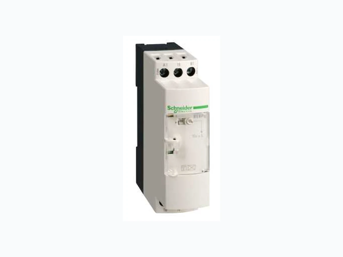
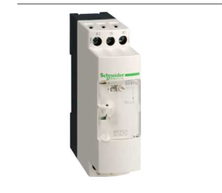
RE8RA41FUTQ SCHNEIDER
Document overview
- PDF pages: 6
Technical content
Page 1
Characteristics
Main
type
voltage
quantity
Complementary
Discrete output type
Relay
Contacts material Width pitch dimension
22.5 mm
Voltage range Connections - terminals
Tightening torque Setting accuracy of time delay Repeat accuracy
< 1 %
Voltage drift
< 2.5 %/V
Temperature drift
< 0.2 %/°C
Minimum pulse duration
26 ms
Reset time
50 ms
Maximum switching voltage
250 V
Mechanical durability [Ith] conventional free air thermal current
8 A
[Ie] rated operational current
Minimum switching capacity Input voltage Maximum switching current Input compatibility Marking
CE
Overvoltage category [Ui] rated insulation voltage
Supply disconnection value
0.1 Uc
Operating position Surge withstand Power consumption in VA
7/9/2011
industrial timing relay - 20..1800 s - type C -
110..240 V AC - 1 C/O
Range of product
Zelio Time
Product or component
Optimum industrial timing relay
Component name
RE8
Time delay type
C
Time delay range
20...1800 s
[Us] rated supply
110...240 V AC, 50/60 Hz
Sale per indivisible
10
90/10 silver nickel contacts
0.9...1.1 Us Screw terminals 2 x 1.5 mm², flexible cablewith cable end Screw terminals 2 x 2.5 mm², flexible cablewithout cable end 0.6...1.1 N.m +/- 20 % of full scale
20000000 cycles
<= 2 A at 24 V, DC-13 for 70 °C conforming to IEC 60947-5-1/1991 <= 2 A at 24 V, DC-13 for 70 °C conforming to VDE 0660 <= 3 A at 24 V, AC-15 for 70 °C conforming to IEC 60947-5-1/1991 <= 3 A at 24 V, AC-15 for 70 °C conforming to VDE 0660 <= 0.1 A at 250 V, DC-13 for 70 °C conforming to IEC 60947-5-1/1991 <= 0.1 A at 250 V, DC-13 for 70 °C conforming to VDE 0660 <= 0.2 A at 115 V, DC-13 for 70 °C conforming to IEC 60947-5-1/1991 <= 0.2 A at 115 V, DC-13 for 70 °C conforming to VDE 0660 10 mA at 12 V 110...240 V (Y1) 10 mA (Y1) 2-wire sensors DC with leakage current < 1 mA, cable length: <= 50 m (Y1)
III conforming to IEC 60664-1 250 V conforming to IEC 300 V conforming to CSA
Any position without derating factor 2 kV conforming to IEC 61000-4-5 level 3 1.8 VA at 110 V 8.5 VA at 240 V
Page 2
Terminal description
(15-16-18)OC_ON (A1-A2)CO (Y1)UNUSED
Height
78 mm
Width
22.5 mm
Depth
80 mm
Product weight
0.11 kg
Environment
Immunity to microbreaks
3 ms
Standards
EN/IEC 61812-1
Product certifications
CSA GL UL
Ambient air temperature for storage
-40...85 °C
Ambient air temperature for operation
-20...60 °C 15...85 % 3K3 conforming to IEC 60721-3-3
Relative humidity
0.35 mm 10...55 Hz conforming to IEC 60068-2-6
Vibration resistance
15 gn (duration = 11 ms conforming to IEC 60068-2-27
Shock resistance IP degree of protection
IP20 (terminals) IP50 (casing) 3 conforming to IEC 60664-1
Pollution degree Dielectric test voltage
2.5 kV
Non-dissipating shock wave
4.8 kV 6 kV in contact conforming to IEC 61000-4-2 level 3
Resistance to electrostatic discharge
8 kV in air conforming to IEC 61000-4-2 level 3 10 V/m conforming to IEC 61000-4-3 level 3
Resistance to electromagnetic fields
2 kV conforming to IEC 61000-4-4 level 3
Resistance to fast transients
CISPR11 group 1- class A
Disturbance radiated/conducted
CISPR22 - class A
RoHS EUR status
Compliant
RoHS EUR conformity date
0626
Page 3
Technical Description
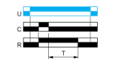
Function C: Timing After Opening of Control Contact
Description
After power-up and closing of the control contact C, the output R closes. When control contact C re-opens, timing T starts. At the end of the timing period, the output(s) R revert(s) to its/their initial state. The second output can be either timed or instantaneous.
Function: 1 Output
Function: 2 Outputs
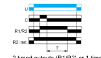
2 timed outputs (R1/R2) or 1 timed output (R1) and 1 instantaneous output (R2 inst.)
Legend
Relay de-energised Relay energised Output open Output closed C Control contact G Gate R Relay or solid state output R1/ 2 timed outputs R2 R2 The second output is instantaneous if the right position is selected inst. T Timing period Ta Adjustable On-delay Tr Adjustable Off-delay U Supply
Page 4
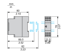
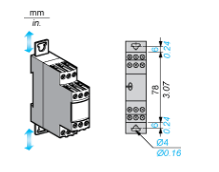
Dimensions Drawings
Width 22.5 mm
Rail Mounting
Screw Fixing
Page 5
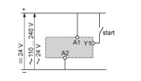
Connections and Schema
Internal Wiring Diagram
Recommended Application Wiring Diagram
Control of Several Relays
Control of several relays with a single external control contact
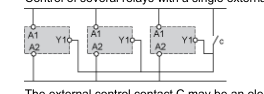
The external control contact C may be an electronic control device, for example a true-wire sensor. In this case A1-A2= 24 Vdc and the control device can only control-up to a maximum of 4 relays.
Connection of a 2-Wire Sensor
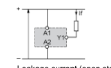
Leakage current (open state) if < 1 mA.
Page 6
Performance Curves
Performance Curves
A.C. Load Curve 1
Electrical durability of contacts on resistive loading millions of operating cycles
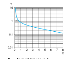
X Current broken in A Y Millions of operating cycles
A.C. Load Curve 2
Reduction factor k for inductive loads (applies to values taken from durability curve 1).
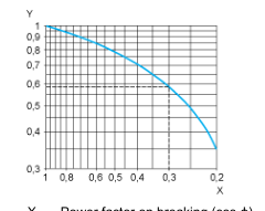
X Power factor on breaking (cos ϕ) Y Reduction factor k Example: An LC1-F185 contactor supplied with 115 V/50 Hz for a consumption of 55 VA or a current consumption equal to 0.1 A and cos ϕ = 0.3. For 0.1 A, curve 1 indicates a durability of approximately 1.5 million operating cycles. As the load is inductive, it is necessary to apply a reduction coefficient k to this number of cycles as indicated by curve 2. For cos ϕ = 0.3: k = 0.6 The electrical durability therefore becomes:1.5 106 operating cycles x 0.6 = 900 000 operating cycles.
D. C. Load Limit Curve
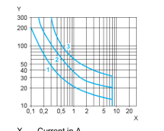
X Current in A Y Voltage in V L/R = 20 ms L/R with load protection diode Resistive load