

 Download PDF
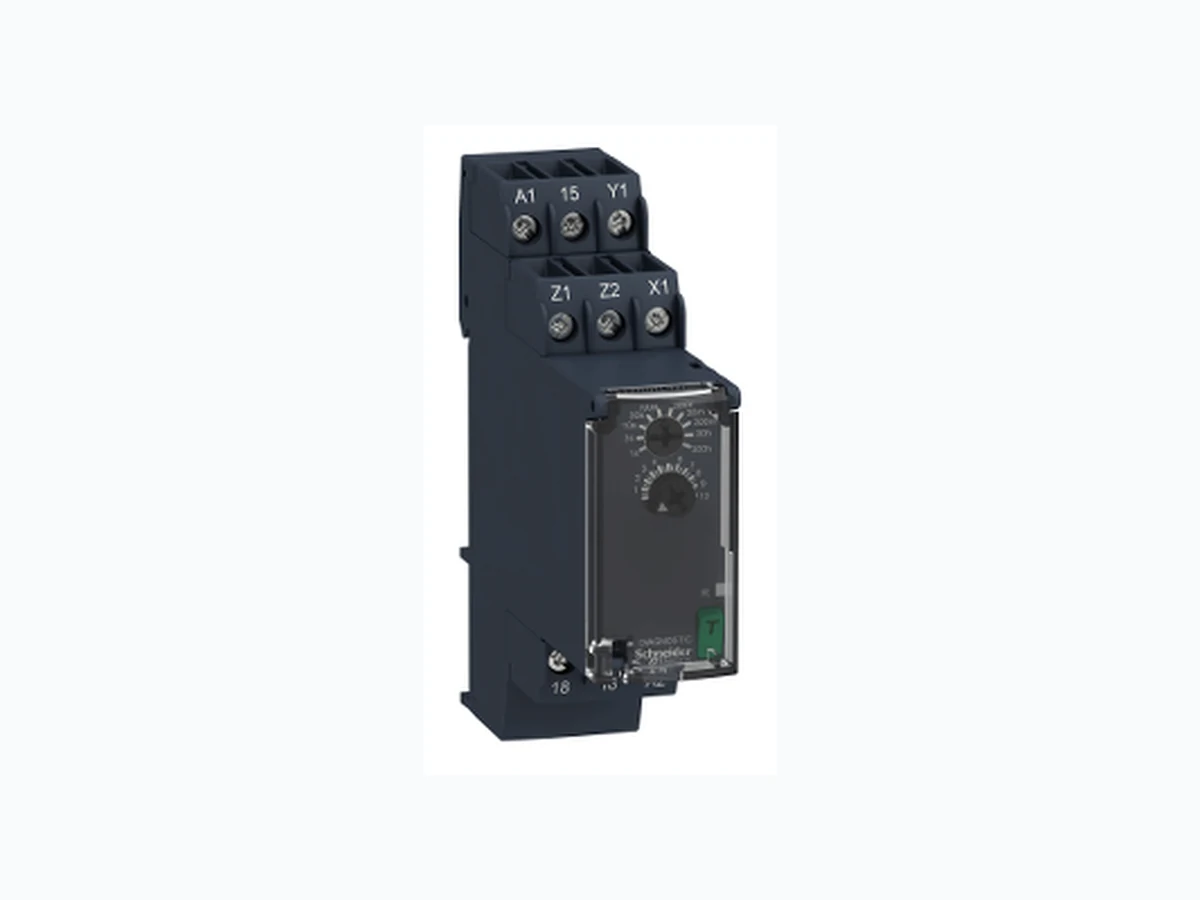
RE22R1ACMR SCHNEIDER
Document overview
- PDF pages: 7
Technical content
Page 1
Harmony, Modular timing relay, 8 A, 1 CO, 0.05
Characteristics
s…300 h, dual function, 24...240 V AC/DC
Product availability : Non-Stock - Not normally stocked in distribution facility
Price\* : 74.24 USD
Main
Range of Product
Harmony Timer Relays
Product or Component Type
Dual function relay
Discrete output type
Relay
Device short name
RE22
Nominal output current
8 A
Complementary
1 C/O timed contact, cadmium free
Contacts type and composition Time delay type
On-delay and off-delay
Time delay range
3...30 min 1...10 s 30...300 s 10...100 s 3...30 s 30...300 min 30...300 h 0.3...3 s 0.05...1 s 3...30 h
Control type
Rotary knob Diagnostic button Potentiometer external
[Us] rated supply voltage
24...240 V AC/DC 50/60 Hz
Release input voltage
<= 2.4 V
Voltage range
0.85...1.1 Us
Supply frequency
50...60 Hz +/- 5 % Screw terminals, 1 x 0.5...1 x 3.3 mm² AWG 20...AWG 12) solid without cable end
Connections - terminals
Screw terminals, 2 x 0.5...2 x 2.5 mm² AWG 20...AWG 14) solid without cable end Screw terminals, 1 x 0.2...1 x 2.5 mm² AWG 24...AWG 14) flexible with cable end
\* Price is “List Price” and may be subject to a trade discount – check with your local distributor or retailer for actual price. Aug 25, 2021
Page 2
Screw terminals, 2 x 0.2...2 x 1.5 mm² (AWG 24...AWG 16) flexible with cable end 5.31…8.85 lbf.in (0.6…1 N.m) IEC 60947-1
Tightening torque Housing material
Self-extinguishing
Repeat accuracy
+/- 0.5 % IEC 61812-1
Temperature Drift
+/- 0.05 %/°C
Voltage drift
+/- 0.2 %/V +/- 10 % of full scale 25 °C IEC 61812-1
Setting accuracy of time delay Control signal pulse width
100 ms with load in parallel 30 ms
Insulation resistance
100 MOhm 500 V DC IEC 60664-1
Recovery time
120 ms on de-energisation
Immunity to microbreaks
10 ms
Power consumption in VA
3 VA 240 V AC
Power consumption in W
1.5 W 240 V DC
Switching capacity in VA
2000 VA
Minimum switching current
10 mA 5 V DC
Maximum switching current
8 A
Maximum switching voltage
250 V AC
Electrical durability
100000 cycles, 8 A at 250 V, AC-1 100000 cycles, 2 A at 24 V, DC-1
Mechanical durability
10000000 cycles
Rated impulse withstand voltage
5 kV 1.2…50 µs IEC 60664-1
Power on delay
100 ms
Creepage distance
4 kV/3 IEC 60664-1
Overvoltage category
III IEC 60664-1
Safety reliability data
B10d = 190000 MTTFd = 205.4 years
Mounting position
Any position 35 mm DIN rail conforming to EN/IEC 60715
Mounting support
Green LED backlight steady)dial pointer indication
Status LED
Yellow LED steady)output relay energised Yellow LED fast flashing)timing in progress and output relay de-energised Yellow LED slow flashing)timing in progress and output relay energised
Maximum Width
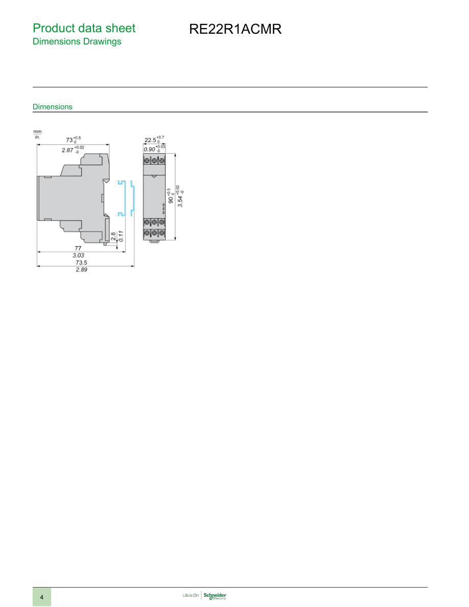
0.89 in (22.5 mm)
Net Weight
0.22 lb(US) (0.1 kg)
Environment
2.5 kV 1 mA/1 minute 50 Hz between relay output and power supply basic insulation IEC 61812-1
Dielectric strength Standards
IEC 61812-1 UL 508
Directives
2006/95/EC - low voltage directive 2004/108/EC - electromagnetic compatibility
Product Certifications
CE CCC GL UL CSA EAC RCM
Ambient Air Temperature for
-4…140 °F (-20…60 °C)
Operation Ambient Air Temperature for Storage
-40…158 °F (-40…70 °C)
IP degree of protection
Housing IP40 IEC 60529 IP50 front face: conforming to IEC 60529 Terminals IP20 IEC 60529
Pollution degree
3 conforming to IEC 60664-1
Vibration resistance
20 m/s² 10…150 Hz)IEC 60068-2-6 15 gn not operating 11 ms IEC 60068-2-27
Shock resistance
Page 3
5 gn in operation 11 ms IEC 60068-2-27
Relative humidity
95 % 77…131 °F (25…55 °C) Fast transients immunity test 1 kV capacitive connecting clip)level 3 IEC 61000-4-4
Electromagnetic compatibility
Surge immunity test - test level: 1 kV level 3 (differential mode) conforming to IEC 61000-4-5 Surge immunity test - test level: 2 kV level 3 (common mode) conforming to IEC 61000-4-5 Electrostatic discharge 6 kV contact discharge)level 3 IEC 61000-4-2 Electrostatic discharge 8 kV air discharge)level 3 IEC 61000-4-2 Radiated radio-frequency electromagnetic field immunity test 10 V/m 80 MHz...1 GHz)level 3 IEC 61000-4-3 Conducted RF disturbances 10 V 0.15...80 MHz)level 3 IEC 61000-4-6 Fast transient bursts 2 kV direct contact)level 3 IEC 61000-4-4 Immunity to microbreaks and voltage drops 30 % 500 ms) IEC 61000-4-11 Immunity to microbreaks and voltage drops 100 % 20 ms) IEC 61000-4-11
Ordering and shipping details
22376 - RELAYS-MEASUREMENT(RM4)
Category Discount Schedule
CP2
GTIN
03606480792403
Nbr. of units in pkg.
1
Package weight(Lbs)
3.53 oz (100 g)
Returnability
No
Country of origin
ID
Packing Units
Unit Type of Package 1
PCE
Package 1 Height
1.02 in (2.6 cm)
Package 1 width
3.23 in (8.2 cm)
Package 1 Length
3.74 in (9.5 cm)
Offer Sustainability
Sustainable offer status
Green Premium product WARNING: This product can expose you to chemicals including: Lead and lead compounds, which
California proposition 65
is known to the State of California to cause cancer and birth defects or other reproductive harm. For more information go to www.P65Warnings.ca.gov
REACh Regulation
REACh Declaration Pro-active compliance (Product out of EU RoHS legal scope)
EU RoHS Directive
EU RoHS Declaration
Mercury free
Yes
RoHS exemption information
Yes
China RoHS Regulation
China RoHS declaration
Environmental Disclosure
Product Environmental Profile
Circularity Profile
End of Life Information
Page 4
Page 5
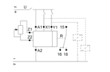
Connections and Schema
Wiring Diagram
Page 6
Technical Description
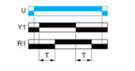
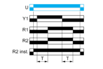
Function Ac: On-Delay & Off-Delay with Control Signal
Description
After energisation of power supply and energization of Y1 causes the timing period T to start. At the end of this timing period, the output(s) R close(s). When deenergization of Y1, the timing T starts. At the end of this timing period T,the output(s) R revert(s) to its/their initial position. The second output (R2) can be either timed (when set to "TIMED") or instantaneous (when set to "INST").
Function: 1 Output
Function: 2 Outputs
Page 7
Technical Description
Function Act: On-Delay & Off-Delay with Control Signal & With Pause / Summation Control
Description
After energisation of power supply and energization of Y1 causes the timing period T to start and the timing can be interrupted / paused each time X1 energizes.When the cumulative total of time periods elapsed reaches the pre-set value T, the output(s) R close(s).When deenergization of Y1, the timing T starts and the timing can be interrupted / paused each time X1 energizes. When the cumulative total of time periods elapsed reaches the pre-set value T, the output(s) R revert(s) to its/their initial position.The second output (R2) can be either timed (when set to "TIMED") or instantaneous (when set to "INST").
Function: 1 Output
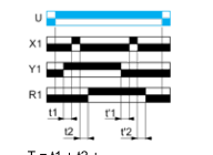
T = t1 + t2 +… T = t'1 + t'2 +…
Function: 2 Outputs
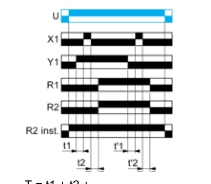
T = t1 + t2 +… T = t'1 + t'2 +…
Legend
Relay de-energised Relay energised Output open Output closed
| U - | Supply |
| T - | Timing period |
| R1/R2 - | 2 timed outputs |
| R2 inst. - | The second output is instantaneous if the right position is selected |
| X1 - | Pause / Summation control |
| Y1 - | Retrigger / Restart control |