


 Download PDF
RCN RFE
Document overview
- PDF pages: 4
Technical content
Page 1
CONSTRUCTION
Glass Passivation
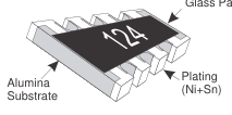
\*These resistors are lead free
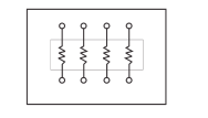
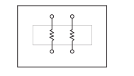
CIRCUITS
04D CIRCUIT
02D CIRCUIT
DIMENSIONS
RCNC24
PART NUMBER EXAMPLE
RCN R 34 - 04D R - 1K0 - J
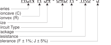
RESISTANCE CODE
| Ohms | 0.0 | 1.0 | 100 | 1.5K | 15K | 1.0 Meg |
| Code | 0R0 | 1R0 | 100R | 1K5 | 15K | 1M0 |
RCNR24 /RCNR34
RCNR64
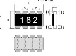
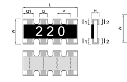
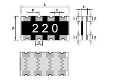
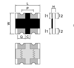
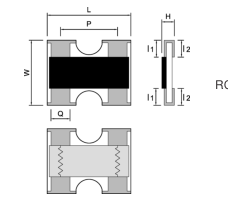
RCNC22
RCNR22
| Series | Dimension | ||||||||
| L | W | H | J | K | P | Q | Q1 | Style | |
| RCNR 22 | 1.0 ± 0.1 | 1.0 ± 0.1 | 0.33 ± 0.05 | 0.15 ± 0.1 | 0.25 ± 0.1 | 0.67 ± 0.1 | 0.34 ± 0.1 | N/A | Array |
| RCNC 22 | 1.0 ± 0.1 | 1.0 ± 0.1 | 0.3 ± 0.1 | 0.25 ± 0.15 | 0.25 ± 0.15 | 0.50 ± 0.1 | 0.35 ± 0.1 | N/A | Array |
| RCNR 24 | 2.0 ± 0.1 | 1.0 ± 0.1 | 0.4 ± 0.1 | 0.2 ± 0.1 | 0.2 ± 0.1 | 0.5 ± 0.1 | 0.3 ± 0.1 | 0.43 ± 0.1 | Array |
| RCNC 24 | 2.0 ± 0.1 | 1.0 ± 0.1 | 0.4 ± 0.1 | 0.2 ± 0.1 | 0.2 ± 0.1 | 0.5 ± 0.1 | 0.3 ± 0.1 | N/A | Array |
| RCNR 34 | 3.2 ± 0.2 | 1.6 ± 0.15 | 0.5 ± 0.1 | 0.3 ± 0.2 | 0.3 ± 0.2 | 0.8 ± 0.2 | 0.5 ± 0.1 | 0.61 ± 0.1 | Array |
| RCNC 34 | 3.2 ± 0.2 | 1.6 ± 0.2 | 0.5 ± 0.1 | 0.4 ± 0.2 | 0.4 ± 0.2 | 0.8 ± 0.1 | 0.4 ± 0.1 | N/A | Array |
| RCNR 64 | 5.1 ± 0.2 | 3.1 ± 0.2 | 0.55 ± 0.15 | 0.55 ± 0.15 | 0.55 ± 0.15 | 1.3 ± 0.2 | 0.9 ± 0.1 | N/A | Array |
Page 1 of 4
Page 2
ELECTRICAL CHARACTERISTICS & RESISTANCE RANGE
| Series | Power Rating Per Element | Max Working Voltage (V) | Max Overload Voltage (V) | Zero Ohm Jumper Rated Current | Resistance Tolerance | Resistance Range (Ώ) | Termperature Coefficient PPM / °C | Standard Circuit Types |
|---|---|---|---|---|---|---|---|---|
| RCNR 22 | 0.063W | 25 | 50 | 1 amp | F (±1%), J (±5%) | 1 ~ 9.9 | 0 ~ +400 | 02D |
| 10 ~ 1M | ±200 | |||||||
| RCNC 22 | 0.063W | 25 | 50 | 1 amp | F (±1%), J (±5%) | 1 ~ 9.9 | 0 ~ +400 | 02D |
| 10 ~ 1M | ±200 | |||||||
| RCNR 24 | 0.063W | 25 | 50 | 1 amp | F (±1%), J (±5%) | 1 ~ 9.9 | 0 ~ +400 | 04D |
| 10 ~ 1M | ±200 | |||||||
| RCNC 24 | 0.063W | 25 | 50 | 1 amp | F (±1%), J (±5%) | 1 ~ 9.9 | 0 ~ +400 | 04D |
| 10 ~ 1M | ±200 | |||||||
| RCNR 34 | 0.1W | 50 | 100 | 1 amp | F (±1%), J (±5%) | 1 ~ 9.9 | 0 ~ +400 | 04D |
| 10 ~ 1M | ±200 | |||||||
| RCNR 64 | 0.25W | 200 | 400 | 2 amps | F (±1%), J (±5%) | 1 ~ 9.9 | 0 ~ +400 | 04D |
| 10 ~ 1M | ±200 |
PERFORMANCE CHARACTERISTICS
Operating Temperature Range
Power Derating Curve
- 55°C to +155°C
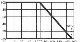
0 20 40 60 70 80 100 120 140 160 Ambient Temperature (°)
Power rating or current rating is in the case based on continuous full-load at ambient temperature of 70ºC. For operation at ambient temperature in excess of 70ºC, the load should be derated in accordance with figure of derating Curve.
Voltage Rating or Current Rating
Resistance Range: >1Ώ
Rated Voltage: The resistor shall have a DC continuous working voltage or a RMS AC continuous working voltage at commercial-line frequency and wave form corresponding to the power rating, as determined formula as follows:
E = Rated Voltage (V) P = Power Rating (W) E = vP x R R = Nominal Resistance (Ώ)
Page 2 of 4
Page 3
OPERATION AND STORAGE TEMPERATURES
| MIN | MAX | |
|---|---|---|
| Operation temperature (at full power) | -55ºC | 70ºC |
| Storage temperature | 20ºC | 30ºC |
| Storage humidity | 30ºC | 70ºC |
TEST PROCEDURES AND REQUIREMENTS
| Test Item | Test Method | Procedure | Requirements |
| Temperature Coefficient of Resistance (T.C.R) | JIS C 5201-1 clause 4.8 | -55°C ~ +155°C, 20°C is the reference temperature | Refer to Ratings |
| Short Time Overload | JIS C 5201-1 clause 4.13 | General: 2.5 times RCWV or Max. Overload voltage for 5 sec. High Power: 2.5 times RCWV or Max. Overload voltage for 2 sec. | ±1 : ±(1.0%+0.05Ω) ±5 : ±(1.0%+0.05Ω) |
| IR Reflow | Sony SS-00254 | 250 +5 1 Peak 250 0 °C 1 230°C or higher 200 1 1 180°C 150 1 150°C 1 90 + 30 s 100 1 30 + 10 s 1 100 Soldering Zone 1 1 Heating Time 50 | ±1 : ±(1.0%+0.05Ω) ±5 : ±(1.0%+0.05Ω) |
| Leaching | Sony SS-00254-9 | 260±5°C for 30 seconds | > 95% Coverage |
| Soldering Heat | JIS C 5201-1 clause 4.18 | 260±5°C for 10 seconds | ±1 : ±(0 . 5 %+0.05Ω) ±5 : ±(1.0%+0.05Ω) |
| Temperature Cycling | JIS C 5201-1 clause 4.19 | -55°C to +155°C, 5 cycles | 0.1%, 0.5%, 1%: ±(0.5%+0.05Ω) 2%, 5%: ±(1.0%+0.10Ω) |
| Electric Iron | Sony SS-00254-5 | Preheating temperature: 350 ±5°C Electric iron preheating time: 3+1/-0 sec. | ±1 : ±(1.0%+0.05Ω) ±5 : ±(1.0%+0.05Ω) |
| Resistance to Solvent | JIS C 5201-1 clause 4.29 | The tested resistor be immersed into isopropyl alcohol of 20~25°C for 60 secs. Then the resistor is left in the room for 48 hrs. | ±1 : ±(0.5%+0.05Ω) ±5 : ±(0.5%+0.05Ω) |
| Load Life in Humidity | JIS C 5201-1 clause 4.24 | 40±2°C, 90~95% R.H. or Max. working voltage for 1,000 hrs with 1.5 hrs "ON" and 0.5 hr "OFF". | 0.1%, 0.5%, 1%: ±(0.5%+0.05Ω) 2%, 5%: ±(2.0%+0.05Ω) |
| Load Life (Endurance) | JIS C 5201-1 clause 4.25 | 70±2°C, or Max. working voltage for 1,000 hrs with 1.5 hrs "ON" and 0.5 hr "OFF". | 0.1%, 0.5%, 1%: ±(1.0%+0.05Ω) 2%, 5%: ±(3.0%+0.10Ω) |
| Insulation Resistance | JIS C 5201-1 clause 4.6 | Max. Overload voltage for 1 minute. | = 10G Ω |
Page 3 of 4
Page 4
PACKAGING
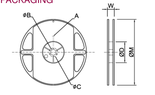
| TYPE | SIZE | A | ΦB | ΦC | ΦD | W | ΦM | |
|---|---|---|---|---|---|---|---|---|
| RCNR22 | 7” | 10K/Reel | 2.0±0.5 | 13.5±1.0 | 21±1.0 | 60±1.0 | 11.5±2.0 | 178±2.0 |
| RCNC22 | ||||||||
| RCNR24 | ||||||||
| RCNC24 | ||||||||
| RCNR34 | 7” | 5K/Reel | 2.0±0.5 | 13.5±1.0 | 21±1.0 | 60±1.0 | 11.5±2.0 | 178±2.0 |
| RCNC64 | 11” | 5K/Reel | 2.0±0.5 | 13.5±1.0 | 21±1.0 | 60±1.0 | 16.0±2.0 | 278±2.0 |
TAPPING SPECIFICATION
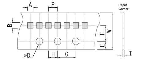
| Packaging | Type | A | B | W | E | F | G | H | T | ΦD | P |
|---|---|---|---|---|---|---|---|---|---|---|---|
| Paper Type | RCNR22 | 1.25±0.10 | 1.25±0.10 | 8.0±0.20 | 1.75±0.10 | 3.5±0.05 | 4.0±0.10 | 2.0±0.05 | 0.45±0.10 | 1.50±0.10 | 2.0±0.1 |
| RCNC22 | 1.25±0.10 | 1.25±0.10 | 8.0±0.20 | 1.75±0.10 | 3.5±0.05 | 4.0±0.10 | 2.0±0.05 | 0.45±0.10 | 1.50±0.10 | ||
| RCNR24 | 1.20±0.10 | 2.20±0.10 | 8.0±0.20 | 1.75±0.10 | 3.5±0.05 | 4.0±0.10 | 2.0±0.05 | 0.60±0.10 | 1.50±0.10 | ||
| RCNC24 | 1.20±0.10 | 2.20±0.10 | 8.0±0.20 | 1.75±0.10 | 3.5±0.05 | 4.0±0.10 | 2.0±0.05 | 0.60±0.10 | 1.50±0.10 | ||
| RCNR34 | 1.90±0.20 | 3.45±0.20 | 8.0±0.20 | 1.75±0.10 | 3.5±0.05 | 4.0±0.10 | 2.0±0.05 | 0.75±0.10 | 1.50±0.10 | 4.0±0.1 |