


 Download PDF
R972 HAMAMATSU
Document overview
- PDF pages: 2
Technical content
Page 1
PHOTOMULTIPLIER TUBE
R972
For VUV Detection, 19 mm (3/4 Inch) Diameter, 10-stage,
Head-On Type, Solar Blind Response (115 nm to 200nm)
GENERAL
| Parameter | Description/Value | Unit | |
|---|---|---|---|
| Spectral Response | 115 to 200 | nm | |
| Wavelength of Maximum Response | 140 | nm | |
| Photocathode | Material | Cs-I | — |
| Minimum Useful Size | 14 | mm dia. | |
| Window Material | MgF2 | — | |
| Dynode | Structure | Linear focused | — |
| Number of Stages | 10 | — | |
| Base | 12 pin base JEDEC No. B12-43 | — | |
| Suitable Socket | E678-12A | — | |
MAXIMUM RATINGS (Absolute Maximum Values)
| Parameter | Value | Unit | |
|---|---|---|---|
| Supply Voltage | Between Anode and Cathode | 2250 | V dc |
| Between Anode and Last Dynode | 250 | V dc | |
| Average Anode Current | 0.01 | mA | |
| Ambient Temperature | -80 to +50 | °C | |
CHARACTERISTICS (at 25 °C)
| Parameter | Min. | Typ. | Max. | Unit | |
|---|---|---|---|---|---|
| Cathode Sensitivity Anode Sensitivity | Radiant at 122 nm Quantum Efficiency at 130 nm Radiant at 122 nm | — — 2.0 × 10² | 12 1.3 1.2 × 10³ | — — — | mA/W % A/W |
| Gain | — | 1.0 × 10⁵ | — | — | |
| Anode Dark Current (after 30 min. storage in darkness) | — | 0.03 | 0.05 | nA | |
| Time Response | Anode Pulse Rise Time | — | 1.6 | — | ns |
| Electron Transit Time | — | 17 | — | ns | |
| VOLTAGE DISTRIBUTION RATIO AND SUPPLY VOLTAGE Electrodes K Dy1 Dy2 Dy3 Dy4 Dy5 Dy6 Dy7 Dy8 Dy9 Dy10 P Ratio 1.5 1 1 1 1 1 1 1 1 1 1 | |||||
Supply Voltage: 2000 V dc, K: Cathode, Dy: Dynode, P: Anode
Subject to local technical requirements and regulations, availability of products included in this promotional material may vary. Please consult with our sales office. Information furnished by HAMAMATSU is believed to be reliable. However, no responsibility is assumed for possible inaccuracies or omissions. Specifications are subject to change without notice. No patent rights are granted to any of the circuits described herein. ©2000 Hamamatsu Photonics K.K.
Page 2
PHOTOMULTIPLIER TUBE R972
Figure 1: Typical Spectral Response
TPMHB0613EA
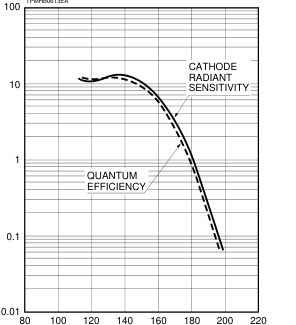
WAVELENGTH (nm)
Figure 3: Dimensional Outline and Basing Diagram (Unit: mm)
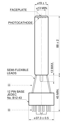
ATemporary Base Removed DY8
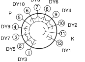
BBottom View P DY10 6 7 DY8 DY9 5 8
DY7
9
4
10
3 DY5
11 2
DY2
DY3 1 12 K DY1
Figure 2: Typical Gain Characteristics
TPMHB0514EA
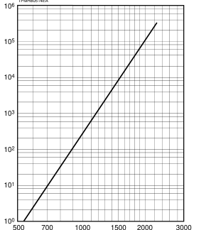
SUPPLY VOLTAGE (V)
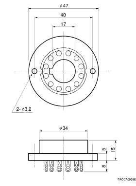
Socket (Option)
(E678-12A)
DY6
DY4
TPMHA0208EA
HOMEPAGE URL http://www.hamamatsu.com
HAMAMATSU PHOTONICS K.K., Electron Tube Center 314-5, Shimokanzo, Toyooka-village, Iwata-gun, Shizuoka-ken, 438-0193, Japan, Telephone: (81)539/62-5248, Fax: (81)539/62-2205 U.S.A.: Hamamatsu Corporation: 360 Foothill Road, P. O. Box 6910, Bridgewater. N.J. 08807-0910, U.S.A., Telephone: (1)908-231-0960, Fax: (1)908-231-1218 E-mail: usa@hamamatsu.com Germany: Hamamatsu Photonics Deutschland GmbH: Arzbergerstr. 10, D-82211 Herrsching am Ammersee, Germany, Telephone: (49)8152-375-0, Fax: (49)8152-2658 E-mail: info@hamamatsu.de France: Hamamatsu Photonics France S.A.R.L.: 8, Rue du Saule Trapu, Parc du Moulin de Massy, 91882 Massy Cedex, France, Telephone: (33)1 69 53 71 00, Fax: (33)1 69 53 71 10 E-mail: infos@hamamatsu.fr
United Kingdom: Hamamatsu Photonics UK Limited: 2 Howard Court, 10 Tewin Road Welwyn Garden City Hertfordshire AL7 1BW, United Kingdom, Telephone: 44-(0)1707-294888, Fax: 44(0)1707-325777 E-mail: info@hamamatsu.co.uk North Europe: Hamamatsu Photonics Norden AB: Smidesvägen 12, SE-171-41 SOLNA, Sweden, Telephone: (46)8-509-031-00, Fax: (46)8-509-031-01 E-mail: info@hamamatsu.se
TPMH1211E02
Italy: Hamamatsu Photonics Italia: S.R.L.: Strada della Moia, 1/E, 20020 Arese, (Milano), Italy, Telephone: (39)02-935 81 733, Fax: (39)02-935 81 741 E-mail: info@hamamatsu.it
NOV. 2000 IP