

 Download PDF
R5900U_07 HAMAMATSU
Document overview
- PDF pages: 4
Technical content
Page 1

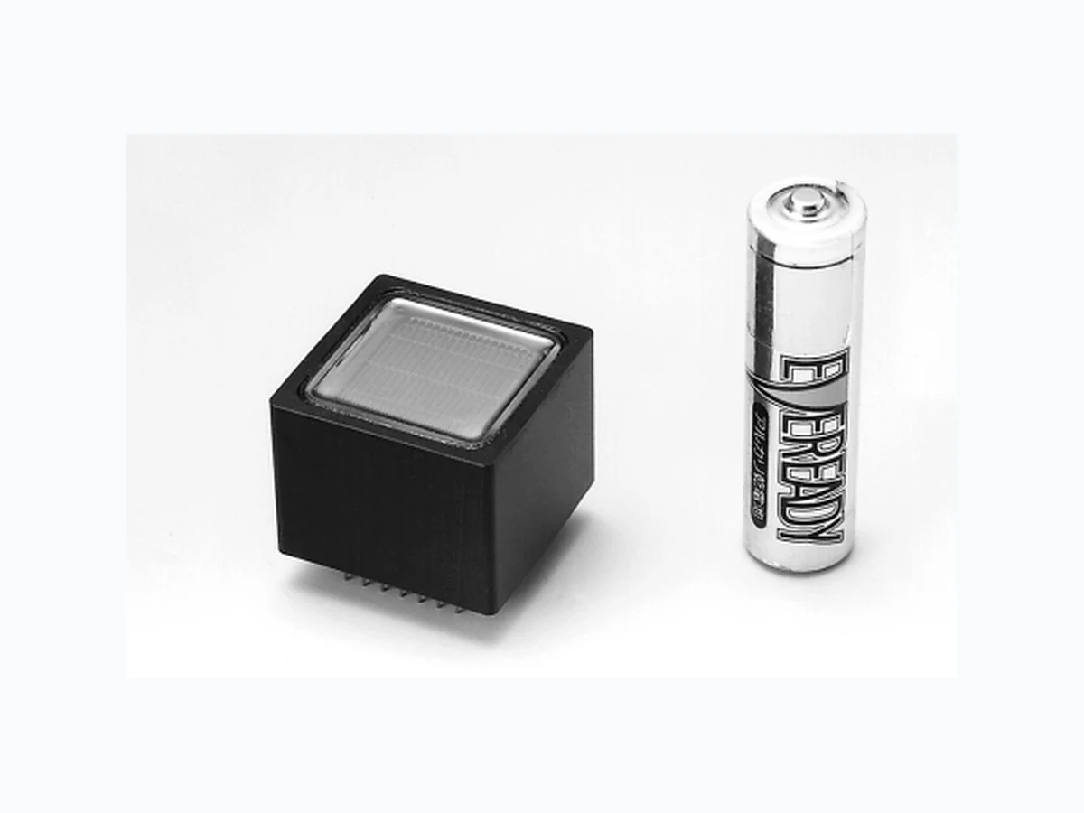
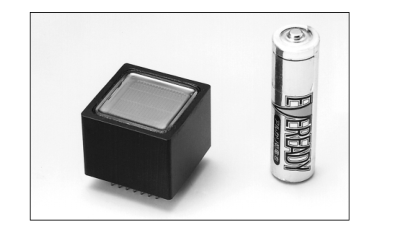
High Speed Response, 30 mm Square, Bialkali and Multialkali Photocathode
10-stage, Head-on Type
FEATURES
GEffective Area: 18 mm × 18 mm GHigh Cathode Sensitivity Luminous 200 µA/lm Typ. (R5900U-01 Type) Luminous 500 µA/lm Typ. (R5900U-20 Type) GHigh Speed Response GWide Dynamic Range GCompact GWeight: Approx. 33 g
APPLICATIONS
GHigh Energy Physics GFlow Cytometer (R5900U-01, -20 Type) GDNA Sequencer (R5900U-01, -20 Type) GPollution Monitoring (NOx) (R5900U-01, -20 Type)
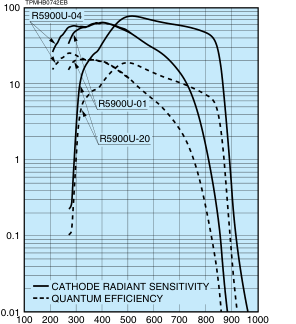
Figure 1: Typical Spectral Response
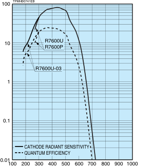
WAVELENGTH (nm)
WAVELENGTH (nm)
Subject to local technical requirements and regulations, availability of products included in this promotional material may vary. Please consult with our sales office. Information furnished by HAMAMATSU is believed to be reliable. However, no responsibility is assumed for possible inaccuracies or omissions. Specifications are subject to change without notice. No patent rights are granted to any of the circuits described herein. ©2007 Hamamatsu Photonics K.K.
Page 2
PHOTOMULTIPLIER TUBE R5900U / R7600U SERIES
| Type No. | Spectral Response | A Photo- cathode Material | B Window Material | C Dynode Structure / Stages | Maximum RatingsD | Cathode Characteristics | ||||
|---|---|---|---|---|---|---|---|---|---|---|
| Range (nm) | Peak Wavelength (nm) | Supply Voltage Between Anode and Cathode (V) | Average Lum Anode Output Current in Total Min. (mA) (µA/lm) | inous Blue Sensitivity Index (CS 5-58) Typ. Typ. (µA/lm) | Red/ White Ratio (R-68) Typ. | Radiant Typ. (mA/W) | ||||
| R7600U | 300 to 650 | 420 | BA | K | MC/10 | 900 | 0.1 60 | 80 9.5 | — | 80 |
| R5900U-01 | 300 to 850 | 420 | MA | K | MC/10 | 900 | 0.1 150 | 200 — | 0.25 | 65 |
| R7600U-03 | 185 to 650 | 420 | BA | U | MC/10 | 900 | 0.1 60 | 80 9.5 | — | 80 |
| R5900U-04 | 185 to 880 | 420 | MA | U | MC/10 | 900 | 0.1 150 | 200 — | 0.25 | 65 |
| R5900U-20 | 300 to 920 | 530 | MA | K | MC/10 | 900 | 0.1 350 | 500 — | 0.4 | 78 |
| R7600P | 300 to 650 | 420 | BA | K | MC/10 | 900 | 0.1 60 | 80 9.5 | — | 80 |
NOTE: A BA: Bialkali, MA: Multialkali B K: Borosilicate glass, U: UV glass C MC: Metal channel D The maximum operating ambient temperature range is -30 °C to +50 °C
Figure 2: Typical Gain
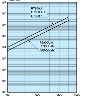
SUPPLY VOLTAGE (V)
Figure 3: Time Response (Example)
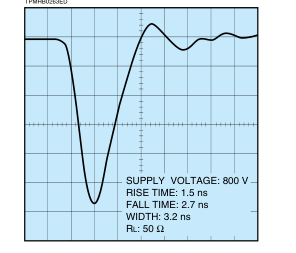
TIME (2 ns/div)
Figure 4: Single Photon Counting (Example)
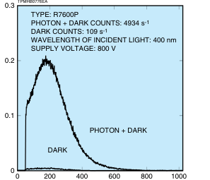
PULSE HEIGHT / CHANNEL NUMBER (ch)
Page 3
| Anode to Cathode Supply Voltage (V) | Anode Characteristics | Pulse Linearity | Type No. | ||||||||||
|---|---|---|---|---|---|---|---|---|---|---|---|---|---|
| Luminous | Gain Typ. | Dark Current (After 30 min) | Dark Count | Time Response | |||||||||
| Min. (A/lm) | Typ. (A/lm) | Rise Time Typ. (ns) | Transit Time Typ. (ns) | TTS Typ. (ns) | 2 % Deviation (mA) | 5 % Deviation (mA) | |||||||
| Typ. (nA) | Max. (nA) | Typ. | Max. | ||||||||||
| 800 | 40 | 160 | 2.0 × 10⁶ | 2 | 20 | — | — | 1.4 | 9.6 | 0.35 | 30 | 60 | R7600U |
| 800 | 50 | 200 | 1.0 × 10⁶ | 10 | 50 | — | — | R5900U-01 | |||||
| 800 | 40 | 160 | 2.0 × 10⁶ | 2 | 20 | — | — | R7600U-03 | |||||
| 800 | 50 | 200 | 1.0 × 10⁶ | 10 | 50 | — | — | R5900U-04 | |||||
| 800 | 100 | 500 | 1.0 × 10⁶ | 20 | 50 | — | — | R5900U-20 | |||||
| 800 | 40 | 160 | 2.0 × 10⁶ | — | — | 200 | 500 | R7600P | |||||
VOLTAGE DISTRIBUTION RATIO AND SUPPLY VOLTAGE
Electrodes
K Dy1 Dy2 Dy3 Dy4 Dy5 Dy6 Dy7
Ratio
1.5 1.5 1.5
1 1 1 1
Supply Voltage: 800 V, K: Cathode, Dy: Dynode, P: Anode
Figure 5: TTS Characteristic (Example)
TPMHB0264EC
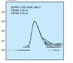
TIME (0.5 ns/div)
Dy8 Dy9 Dy10 P 1 1 1 1
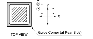
Figure 6: Effect of Magnetic Fields on Anode Output (Example)
Ebb: -800 V
TPMHB0261EE
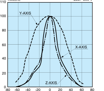
MAGNETIC FLUX DENSITY (mT)
Z
Page 4
PHOTOMULTIPLIER TUBE R5900U / R7600U SERIES
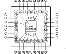
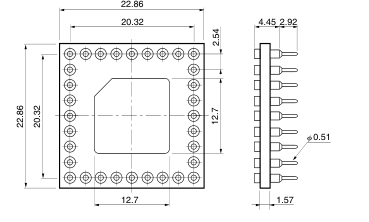
Figure 7: Dimensional Outline and Basing Diagram (Unit: mm)
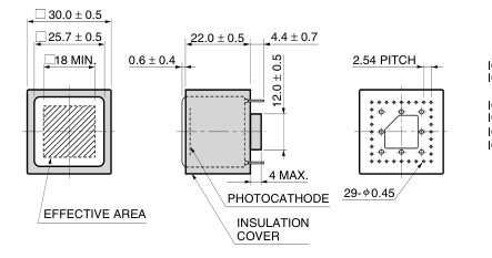
TOP VIEW
SIDE VIEW
BOTTOM VIEW
[ACCESSORIES] (Unit: mm) SOLD SEPARATELY
G Scoket E678-32B
G D Type Scoket Assembly E5996
K : Photocathode Dy : Dynode P : Anode CUT : Short Pin IC : Internal Connection (Don't Use) Basing Diagram
TPMHA0278EI
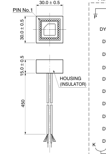
MATERIAL: Glass Epoxy
TACCA0094ED
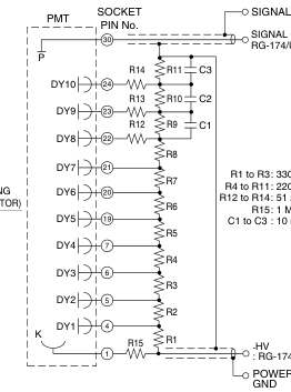
WARNING ~ High Voltage ~
SIGNAL GND
SIGNAL OUTPUT RG-174/U (BLACK)
: 330 kΩ : 220 kΩ
: 10 nF
: RG-174U (RED) POWER SUPPLY
TACCA0234EC
The product is operated at high voltage potential. Further, the metal housing of the product is connected to the photocathode (potential) so that it becomes a high voltage potential when the product is operated at a negative high voltage (anode grounded). Accordingly, extreme safety care must be taken for the electrical shock hazard to the operator or the damage to the other instruments.
\* PATENT: USA: 5410211 and other(9), GBR: 551767 and other(9), DEU: 69209809 and other(9), FRA: 551767 and other(9), JPN: 3078905 and other(9)
WEB SITE www.hamamatsu.com
HAMAMATSU PHOTONICS K.K., Electron Tube Division 314-5, Shimokanzo, Iwata City, Shizuoka Pref., 438-0193, Japan, Telephone: (81)539/62-5248, Fax: (81)539/62-2205 U.S.A.: Hamamatsu Corporation: 360 Foothill Road, P. O. Box 6910, Bridgewater. N.J. 08807-0910, U.S.A., Telephone: (1)908-231-0960, Fax: (1)908-231-1218 E-mail: usa@hamamatsu.com Germany: Hamamatsu Photonics Deutschland GmbH: Arzbergerstr. 10, D-82211 Herrsching am Ammersee, Germany, Telephone: (49)8152-375-0, Fax: (49)8152-2658 E-mail: info@hamamatsu.de France: Hamamatsu Photonics France S.A.R.L.: 19, Rue du Saule Trapu, Parc du Moulin de Massy, 91882 Massy Cedex, France, Telephone: (33)1 69 53 71 00, Fax: (33)1 69 53 71 10 E-mail: infos@hamamatsu.fr
United Kingdom: Hamamatsu Photonics UK Limited: 2 Howard Court, 10 Tewin Road Welwyn Garden City Hertfordshire AL7 1BW, United Kingdom, Telephone: 44-(0)1707-294888, Fax: 44(0)1707-325777 E-mail: info@hamamatsu.co.uk North Europe: Hamamatsu Photonics Norden AB: Smidesvägen 12, SE-171-41 SOLNA, Sweden, Telephone: (46)8-509-031-00, Fax: (46)8-509-031-01 E-mail: info@hamamatsu.se
TPMH1291E03
Italy: Hamamatsu Photonics Italia: S.R.L.: Strada della Moia, 1/E, 20020 Arese, (Milano), Italy, Telephone: (39)02-935 81 733, Fax: (39)02-935 81 741 E-mail: info@hamamatsu.it
SEPT. 2007 IP