

 Download PDF
R6350_05 HAMAMATSU
Document overview
- PDF pages: 8
Technical content
Page 1

13 mm (1/2 Inch) Diameter, 9-stage, Side-on Type
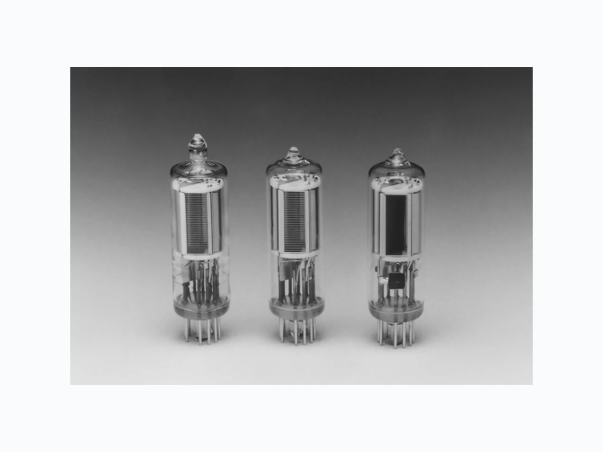
The R6350 to R6358 series are compact side-on photomultiplier tubes with a 13 mm diameter and 50 mm height. Using different photocathode and window material combinations helped to produce a full product lineup to cover a wide spectral response range from the UV to the near infrared. This allows selecting the optimal tube to match your application and wavelength to be detected, the same as when selecting the popular 28 mm (1-1/8 inch) side-on tubes. The R6356-06 and R6357 do not use an entrance mesh (grill) which is usually installed just inside the light input window. This eliminates the light loss caused by the entrance mesh, even if the size of incident light beam is small.
APPLICATIONS
GEmission Spectroscopy (ICP, Direct Reader) GEnvironmental Monitoring (NOx, SO2, etc.) GFluorescence Immunoassay GChemiluminescence Immunoassay GHygiene Monitor (Bio Luminescence) GX-ray Phototimer GFluorometer GMicroscope (Laser Scanning Microscope)
Left: Fused silica window Center: UV window Right: Meshless type (R6356-06, R6357)
Subject to local technical requirements and regulations, availability of products included in this promotional material may vary. Please consult with our sales office. Information furnished by HAMAMATSU is believed to be reliable. However, no responsibility is assumed for possible inaccuracies or omissions. Specifications are subject to change without notice. No patent rights are granted to any of the circuits described herein. ©2005 Hamamatsu Photonics K.K.
Page 2
Side-On Compact Type Photomultiplier Tubes
| Type No. | Remarks | Spectral Response | A Photo- cathode Material | B Window Material | C Outline No. | D Dynode Structure No. of Stages | Socket Socket Assembly | MaximumF Ratings | Cathode Sensitivity | |||
|---|---|---|---|---|---|---|---|---|---|---|---|---|
| Range (nm) | Peak Wave- length (nm) | Luminous | ||||||||||
| Anode to Cathode Voltage (V) | G Average Anode Current (mA) | Min. (µA/lm) | Typ. (µA/lm) | |||||||||
| R6350 | For UV to visible range, general purpose. | 185 to 650 | 340 | Sb-Cs | U | 1 | CC/9 | E678-11U/E | 1250 | 0.01 | 20 | 40 |
| R6351 | Synthetic silica window type of R6350 | 160 to 650 | 340 | Sb-Cs | Q | 2 | CC/9 | E678-11U/E | 1250 | 0.01 | 20 | 40 |
| R6352 | High sensitivity variant of R6350 | 185 to 750 | 420 | BA | U | 1 | CC/9 | E678-11U/E | 1250 | 0.01 | 80 | 120 |
| R6353 | Low dark current bialkali photocathode | 185 to 680 | 400 | LBA | U | 1 | CC/9 | E678-11U/E | 1250 | 0.01 | 30 | 70 |
| R6354 | For UV range | 160 to 320 | 230 | Cs-Te | Q | 2 | CC/9 | E678-11U/E | 1250 | 0.01 | — | — |
| R6355 | For UV to near IR range, general purpose | 185 to 850 | 530 | MA | U | 1 | CC/9 | E678-11U/E | 1250 | 0.01 | 80 | 150 |
| R6356-06 * | High sensitivity variant of R6355 Meshless type | 185 to 900 | 400 | MA | U | 1 | CC/9 | E678-11U/E | 1250 | 0.01 | 200 | 300 |
| R6357 * | High sensitivity variant of R6356-06, Meshless type | 185 to 900 | 450 | MA | U | 1 | CC/9 | E678-11U/E | 1250 | 0.01 | 350 | 500 |
| R6358 | Low dark current multialkali photocathode | 185 to 830 | 530 | LMA | U | 1 | CC/9 | E678-11U/E | 1250 | 0.01 | 140 | 200 |
\* Achieved the higher photocathode sensitivity by eliminating the mesh in front of the photocathode. It also features no output variation, disturbed by the mesh, when the incident light spot to the photocathode is small. NOTE: A Photocathode materials
B Window materials
BA: Bialkali
Q: Fused silica
LBA: Low dark current bialkali
U: UV glass
MA: Multialkali LMA: Low dark current multialkali D Dynode structure
E See optional accessories
CC: Circular-cage G Averaged over any interval of 30 seconds maximum.
C Outline No. See Fig. 9
F The maximum operating ambient temperature range is -30 °C to +50 °C.
Page 3
| Cathode Sensitivity | K Anode to Cathode Supply Voltage (V) | Anode CharacteristicsL | Notes | Type No. | |||||||||
| Blue Sens. Index (CS 5-58) Typ. | H Red/ White Ratio Typ. | J Radiant Typ. (mA/W) | Anode Sensitivity | Gain Typ. | Anode Dark Current (After 30 min.) | Time Response | |||||||
| Luminous | J Radiant Typ. (A/W) | Rise Time Typ. (ns) | Electron Transit Time Typ. (ns) | ||||||||||
| Min. (A/lm) | Typ. (A/lm) | ||||||||||||
| Typ. (nA) | Max. (nA) | ||||||||||||
| 5 | — | 48 | 1000 | 50 | 300 | 3.6 × 10⁵ | 7.5 × 10⁶ | 0.5 | 5 | 1.4 | 15 | Photon counting type: R6350P Dark Count 30 s-1 Max. | R6350 |
| 5 | — | 48 | 1000 | 50 | 300 | 3.6 × 10⁵ | 7.5 × 10⁶ | 0.5 | 5 | 1.4 | 15 | R6351 | |
| 10 | — | 90 | 1000 | 100 | 700 | 5.2 × 10⁵ | 5.8 × 10⁶ | 1 | 10 | 1.4 | 15 | R6352 | |
| 6.5 | — | 65 | 1000 | 100 | 400 | 3.7 × 10⁵ | 5.7 × 10⁶ | 0.1 | 2 | 1.4 | 15 | Photon counting type: R6353P Dark Count 30 s-1 Max. | R6353 |
| — | — | M 62 | 1000 | — | — | M 1.8 × 10⁵ | 3 × 10⁶ | 0.5 | 5 | 1.4 | 15 | R6354 | |
| 6 | 0.15 | 45 | 1000 | 100 | 600 | 1.8 × 10⁵ | 4 × 10⁶ | 1 | 10 | 1.4 | 15 | R6355 | |
| 10 | 0.3 | 77 | 1000 | 400 | 2000 | 5.2 × 10⁵ | 6.7 × 10⁶ | 1 | 10 | 1.4 | 15 | R6356-06 * | |
| 13 | 0.4 | 105 | 1000 | 1000 | 2000 | 4.2 × 10⁵ | 4 × 10⁶ | 2 | 10 | 1.4 | 15 | R6357 * | |
| 7.5 | 0.15 | 70 | 1000 | 300 | 700 | 2.5 × 10⁵ | 3.5 × 10⁶ | 0.1 | 1 | 1.4 | 15 | Photon counting type: R6358-10 Dark Count 300 s-1 Max. | R6358 |
H Measured using red filter Toshiba R-68.
L Anode characteristics are measured with the supply voltage M: at 254 nm and voltage distribution ratio specified by Note N. N Voltage distribution ratio and voltage. Electrodes
K Dy1 Dy2 Dy3 Dy4 Dy5 Dy6
Distribution Ratio 1
1 1 1 1 1
Supply Voltage: 1000 V, K: Cathode, Dy: Dynode, P: Anode
J Measured at the peak wavelength.
K Refer to Note N.
Dy7 Dy8 Dy9 P 1 1 1 1
Page 4
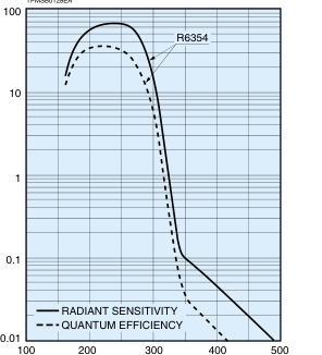
Figure 1: Typical Spectral Response of Cs-Te
TPMSB0128EA
WAVELENGTH (nm)
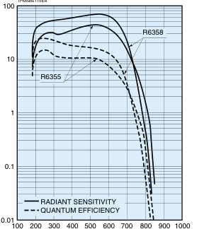
Figure 3: Typical Spectral Response of MA, LMA
TPMSB0115EA
WAVELENGTH (nm)
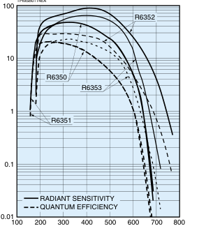
Figure 2: Typical Spectral Response of BA, LBA, Sb-Cs
TPMSB0114EA
WAVELENGTH (nm)
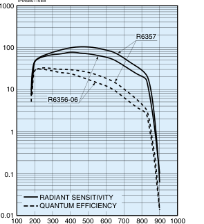
Figure 4: Typical Spectral Response of High Sensitivity MA
TPMSB0116EB
WAVELENGTH (nm)
Page 5
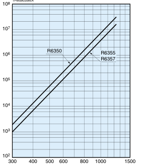
Figure 5: Typical Gain
TPMSB0208EA
SUPPLY VOLTAGE (V)
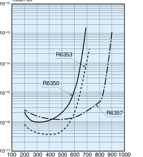
Figure 7: Typical ENI Characteristics
TPMSB0119EA
WAVELENGTH (nm)
Figure 6: Typical Time Response
TPMSB0118EA
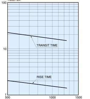
SUPPLY VOLTAGE (V)
Figure 8: Typical Anode Uniformity
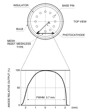
LEFT
RIGHT
TPMSC0036EA
Page 6
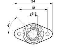
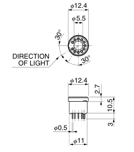
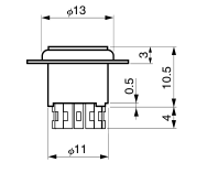
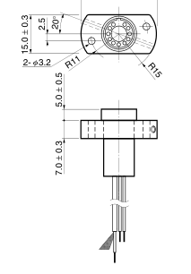
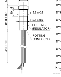
Figure 9: Dimensional Outline and Basing Diagram (Unit: mm)
Outline No.1
Outline No.2
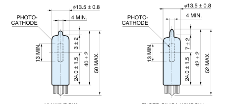
DY6
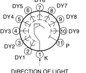
DIRECTION OF LIGHT
BOTTOM VIEW
UV WINDOW
FUSED SILICA WINDOW
TPMSA0034EB
Socket
E678-11U
E678-11T (Sold Separately):
For direct soldering to PC board
TACCA0181EB
TACCA0161EB
Page 7
OPTIONAL ACCESSORIES
D-Type Socket Assembly
| Type No. | Grounded Electrode / Supply Voltage Polarity | Maximum RatingsD | B Leakage Current in Signal Max. (A) | Total Voltage Divider Resistance (MΩ) | C Maximum Linear Output in DC Mode (µA) | Signal Output | ||
|---|---|---|---|---|---|---|---|---|
| Supply Voltage between Case and Pins (V) | Supply Voltage between Power Supply Terminals (V) | A Voltage Divider Current (mA) | ||||||
| E850-13E | Anode / – | 1500 | 1250 | 0.38 | 1 × 10⁻¹⁰ | 3.3 | 18 (at 1250 V) | DC/Pulse |
E850-22: with SHV, BNC connector
NOTE: A Measured with the maximum supply voltage. B Measured with a supply voltage of 1000 V. C The current at which the output linearity is kept within ±5 %. D Operating temperature range is -20 °C to +50 °C. E Supplied with a separate mounting flange. See below for assembled dimensions.
Dimensional Outline and Circuit Diagram (Unit: mm)
E850-13
Mounting Flange for E850-13
SOCKET
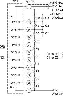
36.0 ± 0.3
SIGNAL GND SIGNAL OUTPUT
RG-174/U (BLACK) POWER SUPPLY GND
14.0 ± 0.3
AWG22 (BLACK)
: 330 kΩ : 10 nF
AWG22 (VIOLET)
TACCA0096EC
TACCA0097EB
Page 8
LENS FOR 1/2 INCH DIAMETER SIDE-ON TYPE PHOTOMULTIPLIER TUBES
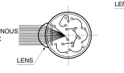
The optimized cylindrical lens which can be attached at the entrance window of 1/2 inch side-on photomultiplier tube. This lens helps
the incident light reaches the photocathode efficiently.
With this lens, the effective area widens by the factor of two in case of 1/2" PMT (7.5 mm width). The lens transmits above 300 nm
light only.
LENS
LUMINOUS FLUX
TPMSC0042EA
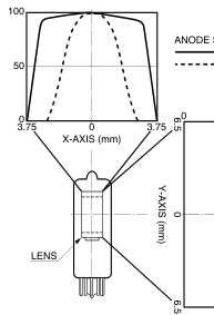
Figure 11: Uniformity
ANODE SENSITIVITY WITH LENS WITHOUT LENS
50 100
MEASUREMENT CONDITIONS WAVELENGTH: 400 nm SUPPLY VOLTAGE: -1000 V A 1 mm diameter spot light (parallel light) is scanned at the center of the photocathode in X and Y directions.
TPMSC0041EA
NOTE: The lens only (without photomultiplier tube) is not available.
WARNING ~High Voltage~
Figure 10: Transmittance of Lens
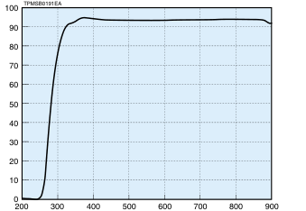
WAVELENGTH (nm)
Lens Material: Acrylic resin
Figure 12: Lens Effect (Ex.: R6358)
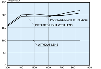
WAVELENGTH (nm)
Parallel light: Uniform and sufficiently large area, than the sensitive area size, of the parallel incident light (40 mm dia.) shall be given to the photomultiplier tube.
Diffused light: Parallel light (40 mm dia.) is given to the photomultiplier tube through the diffuser, which locates 10 cm from the tube.
The product is operated at high voltage potential. Further, the metal housing of the product is connected to the photocathode (potential) so that it becomes a high voltage potential when the product is operated at a negative high voltage (anode grounded). Accordingly, extreme safety care must be taken for the electrical shock hazard to the operator or the damage to the other instruments.
WEB SITE http://www.hamamatsu.com
HAMAMATSU PHOTONICS K.K., Electron Tube Division 314-5, Shimokanzo, Iwata City, Shizuoka Pref., 438-0193, Japan, Telephone: (81)539/62-5248, Fax: (81)539/62-2205 U.S.A.: Hamamatsu Corporation: 360 Foothill Road, P. O. Box 6910, Bridgewater. N.J. 08807-0910, U.S.A., Telephone: (1)908-231-0960, Fax: (1)908-231-1218 E-mail: usa@hamamatsu.com Germany: Hamamatsu Photonics Deutschland GmbH: Arzbergerstr. 10, D-82211 Herrsching am Ammersee, Germany, Telephone: (49)8152-375-0, Fax: (49)8152-2658 E-mail: info@hamamatsu.de France: Hamamatsu Photonics France S.A.R.L.: 8, Rue du Saule Trapu, Parc du Moulin de Massy, 91882 Massy Cedex, France, Telephone: (33)1 69 53 71 00, Fax: (33)1 69 53 71 10 E-mail: infos@hamamatsu.fr
United Kingdom: Hamamatsu Photonics UK Limited: 2 Howard Court, 10 Tewin Road Welwyn Garden City Hertfordshire AL7 1BW, United Kingdom, Telephone: 44-(0)1707-294888, Fax: 44(0)1707-325777 E-mail: info@hamamatsu.co.uk North Europe: Hamamatsu Photonics Norden AB: Smidesvägen 12, SE-171-41 SOLNA, Sweden, Telephone: (46)8-509-031-00, Fax: (46)8-509-031-01 E-mail: info@hamamatsu.se
TPMS1032E05
Italy: Hamamatsu Photonics Italia: S.R.L.: Strada della Moia, 1/E, 20020 Arese, (Milano), Italy, Telephone: (39)02-935 81 733, Fax: (39)02-935 81 741 E-mail: info@hamamatsu.it
JUN. 2005. IP