
DATASHEET SEARCH SITE
Document overview
- Manufacturer or author: Provided By www.digicamel.com(FREE DATASHEET DOWNLOAD SITE)
- PDF pages: 108
Technical content
Features
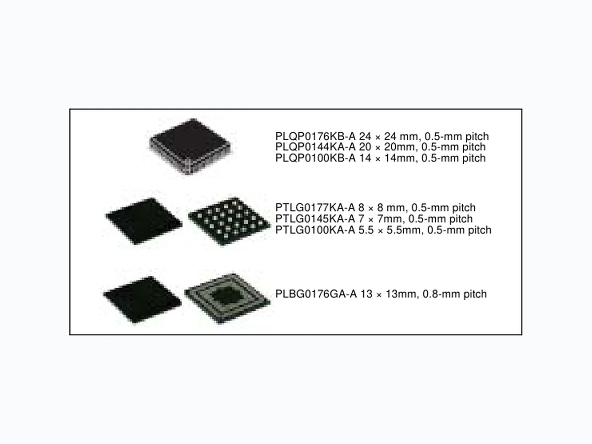
RX63N Group products incorporate an Ethernet controller while RX631 Group products do not. ■32-bit RX CPU core Max. operating frequency: 100 MHz Capable of 165 DMIPS in operation at 100 MHz Single precision 32-bit IEEE-754 floating point Two types of multiply-and-accumulation unit (between memories and between registers) 32-bit multiplier (fastest instruction execution takes one CPU clock cycle) Divider (fastest instruction execution takes two CPU clock cycles) Fast interrupt CISC Harvard architecture with 5-stage pipeline Variable-length instructions: Ultra-compact code Supports the memory protection unit (MPU) JTAG and FINE (two-line) debugging interfaces ■Low-power design and architecture Operation from a single 2.7- to 3.6-V supply Low power consumption: A product that supports all peripheral functions draws only 500 μA/MHz. RTC is capable of operation from a dedicated power supply (min. operating voltage: 2 V). Four low-power modes ■On-chip main flash memory, no wait states Supports ROM-less versions and versions with up to 2 Mbytes of ROM (ROM-less version: RX631 Group only) 100-MHz operation, 10-ns read cycle (no wait states) 384-Kbyte to 2-Mbyte capacities User code programmable via the USB, SCI, or JTAG ■On-chip data flash memory ROM-less or 32 Kbytes of ROM (reprogrammable up to 100,000 times) Programming/erasing as background operations (BGOs) ■On-chip SRAM, no wait states 32- to 128-Kbyte capacities For instructions and operands Can provide backup on deep software standby ■DMA DMAC: Four channels DTC EXDMAC: Two channels Dedicated DMAC for the Ethernet controller: Single channel ■Reset and supply management Power-on reset (POR) Low voltage detection (LVD) with voltage settings ■Clock functions External crystal oscillator or internal PLL for operation at 4 to 16 MHz Internal 125-kHz LOCO and 50-MHz HOCO Dedicated 125-kHz LOCO for the IWDT ■Real-time clock Adjustment functions (30 seconds, leap year, and error) Time capture function (for capturing times in response to event-signal input on external pins) ■Independent watchdog timer 125-kHz LOCO clock operation ■Useful functions for IEC60730 compliance Oscillation-stoppage detection, frequency measurement, CRC, IWDT, self- diagnostic function for the A/D converter, etc. ■Various communications interfaces Ethernet MAC (1) (not in RX631 Group products) Host/function or OTG controller (1) and function controller (1) with full- speed USB 2.0 transfer CAN (compliant with ISO11898-1), incorporating 32 mailboxes (up to 3 modules) SCI with multiple functionalities (up to 13) Choose from among asynchronous mode, clock-synchronous mode, smart- card interface mode, simplified SPI, simplified I2C, and extended serial mode. I 2C bus interface for transfer at up to 1 Mbps (up to 4) RSPI for high-speed transfer (up to 3) ■External address space Buses for high-speed data transfer (max. operating frequency of 50 MHz) 8 CS areas (8 × 16 Mbytes) Multiplexed address data or separate address lines are selectable per area. 8-, 16-, or 32-bit bus space is selectable per area Independent SDRAM area (128 Mbytes) ■Up to 20 extended-function timers 16-bit MTU2: input capture, output compare, PWM waveform output, phase-counting mode (6 channels) 16-bit TPU: input capture, output compare, phase-counting mode (12 channels) 8-bit TMR (4 channels) 16-bit compare-match timers (4 channels) ■A/D converter for 1-MHz Operation Up to 21 12-bit channels, and incorporating 1 sample-and-hold circuit Up to 8 10-bit channels, and incorporating 1 sample-and-hold circuit Addition of results of A/D conversion (in the 12-bit converter) Self diagnosis (for the 10-bit converter) ■10-bit D/A converter: 2 channels ■Temperature sensor for measuring temperature within the chip ■Register write protection can protect values in important registers against overwriting. ■Up to 134 pins for GPIO 5-V tolerance, open drain, input pull-up, switchable driving ability ■Operating temp. range –40°C to +85°C PLQP0176KB-A 24 × 24 mm, 0.5-mm pitch PLQP0144KA-A 20 × 20mm, 0.5-mm pitch PLQP0100KB-A 14 × 14mm, 0.5-mm pitch PTLG0177KA-A 8 × 8 mm, 0.5-mm pitch PTLG0145KA-A 7 × 7mm, 0.5-mm pitch PTLG0100KA-A 5.5 × 5.5mm, 0.5-mm pitch PLBG0176GA-A 13 × 13mm, 0.8-mm pitch 100-MHz 32-bit RX MCU, on-chip FPU, 165 DMIPS, up to 2-MB flash memory, Ethernet MAC, full-speed USB 2.0 host/function/OTG interface, various communications interfaces including CAN, 10- & 12-bit A/D converters, RTC R01DS0098EJ0090 Rev.0.90 Dec 27, 2011
R01DS0098EJ0090 Rev.0.90 Page 2 of 106 Dec 27, 2011 RX63N Group, RX631 Group 1. Overview Under development Preliminary document Specifications in this document are tentative and subject to change. 1. Overview
1.1 Outline of Specifications
Table 1.1 lists the specifications in outline, and table 1.2 gives a comparison of the functions of products in different packages. Table 1.1 is for products with the greatest number of functions, so numbers of peripheral modules and channels will differ in accord with the package. For details, see Table 1.2, Comparison of Functions for Different Packages in the RX63N/RX631 Group. Table 1.1 Outline of Specifications (1/5) Classification Module/Function Description CPU CPU Maximum operating frequency: 100 MHz 32-bit RX CPU Minimum instruction execution time: One instruction per state (cycle of the system clock) Address space: 4-Gbyte linear Register set of the CPU General purpose: Sixteen 32-bit registers Control: Nine 32-bit registers Accumulator: One 64-bit register Basic instructions: 73 Floating-point instructions: 8 DSP instructions: 9 Addressing modes: 10 Data arrangement Instructions: Little endian Data: Selectable as little endian or big endian On-chip 32-bit multiplier: 32 x 32 64 bits On-chip divider: 32 / 32 32 bits Barrel shifter: 32 bits FPU Single precision (32-bit) floating point Data types and floating-point exceptions in conformance with the IEEE754 standard Memory ROM ROM capacity: 2 Mbytes (max.) Two on-board programming modes Boot mode (The user area is programmable via the SCI and USB.) User program mode Parallel programmer mode (for off-board programming) RAM RAM capacity: 128 Kbytes (max.) E2 data flash Data ROM capacity: 32 Kbytes MCU operating modes Single-chip mode, on-chip ROM enabled expansion mode, and on-chip ROM disabled expansion mode (software switching) Clock Clock generation circuit Main clock oscillator, subclock oscillator, low-speed/high-speed on-chip oscillator, PLL frequency synthesizer, and IWDT-dedicated on-chip oscillator Main-clock oscillation stoppage detection Separate frequency-division and multiplication settings for the system clock (ICLK), peripheral module clock (PCLK), and external bus clock (BCLK) The CPU and other bus masters run in synchronization with the system clock (ICLK): Up to 100 MHz Peripheral modules run in synchronization with the peripheral module clock (PCLK): Up to 50 MHz Devices connected to the external bus run in synchronization with the external bus clock (BCLK): Up to 50 MHz Reset Pin reset, power-on reset, voltage-monitoring reset, independent watchdog timer reset, watchdog timer reset, deep software standby reset, and software reset Voltage detection circuit When the voltage on VCC passes the voltage detection level (Vdet), an internal reset or internal interrupt is generated.
R01DS0098EJ0090 Rev.0.90 Page 3 of 106 Dec 27, 2011 RX63N Group, RX631 Group 1. Overview Under development Preliminary document Specifications in this document are tentative and subject to change. Low power consumption Low power consumption facilities Module stop function Four low power consumption modes Sleep mode, all-module clock stop mode, software standby mode, and deep software standby mode Battery backup function Interrupt Interrupt controller (ICUb) Peripheral function interrupts: 187 sources External interrupts: 16 (pins IRQ0 to IRQ15) Software interrupts: One source Non-maskable interrupts: 6 sources Sixteen levels specifiable for the order of priority External bus extension The external address space can be divided into nine areas (CS0 to CS7, SDCS), each with independent control of access settings. Capacity of each area: 16 Mbytes (CS0 to CS7), 128 Mbytes (SDCS) A chip-select signal (CS0# to CS7#, SDCS#) can be output for each area. Each area is specifiable as an 8-, 16-, or 32-bit bus space. The data arrangement in each area is selectable as little or big endian (only for data). SDRAM interface connectable Bus format: Separate bus, multiplex bus Wait control Write buffer facility DMA DMA controller (DMAC) 4 channels Three transfer modes: Normal transfer, repeat transfer, and block transfer Activation sources: Software trigger, external interrupts, and interrupt requests from peripheral functions EXDMA controller (EXDMACa) 2 channels Four transfer modes: Normal transfer, repeat transfer, block transfer, and cluster transfer Single-address transfer enabled with the EDACK signal Capable of direct data transfer to TFT LCD panels Activation sources: Software trigger, external DMA requests (EDREQ), and interrupt requests from peripheral functions Data transfer controller (DTCa) Three transfer modes: Normal transfer, repeat transfer, and block transfer Activation sources: External interrupts and interrupt requests from peripheral functions I/O ports Programmable I/O ports I/O ports for the 177-pin TFLGA (in the planning stage), 176-pin LFBGA (in the planning stage), and 176-pin LQFP I/O pins: 133 Input pins: 1 Pull-up resistors: 133 Open-drain outputs: 133 5-V tolerance: 18 I/O ports for the 145-pin TFLGA (in the planning stage) and 144-pin LQFP I/O pins: 111 Input pins: 1 Pull-up resistors: 111 Open-drain outputs: 111 5-V tolerance: 18 I/O ports for the 100-pin LQFP I/O pins: 78 Input pins: 1 Pull-up resistors: 78 Open-drain outputs: 78 5-V tolerance: 17 Table 1.1 Outline of Specifications (2/5) Classification Module/Function Description
R01DS0098EJ0090 Rev.0.90 Page 4 of 106 Dec 27, 2011 RX63N Group, RX631 Group 1. Overview Under development Preliminary document Specifications in this document are tentative and subject to change. Timers 16-bit timer pulse unit (TPUa) (16 bits x 6 channels) x 2 unit Maximum of 16 pulse-input/output possible Select from among seven or eight counter-input clock signals for each channel Input capture/output compare function Output of PWM waveforms in up to 15 phases in PWM mode Buffered operation and phase-counting mode (two phase encoder input) depending on the channel Support for cascade-connected operation (32 bits x 2 channels) PPG output trigger can be generated Capable of generating conversion start triggers for the A/D converters Signals from the input capture pins are input via a digital filter Clock frequency measuring method Multi-function timer pulse unit 2 (MTU2a) (16 bits x 6 channels) x 1 unit Time bases for the 6 16-bit timer channels can be provided via up to 16 pulse-input/ output lines and three pulse-input lines Select from among eight counter-input clock signals for each channel (PCLK/1, PCLK/ 4, PCLK/16, PCLK/64, TCLKA, TCLKB, TCLKC, TCLKD) other than channel 5, for which only four signals are available. Input capture function 21 output compare/input capture registers Complementary PWM output mode Reset synchronous PWM mode Phase-counting mode Generation of triggers for A/D converter conversion Digital filter Signals from the input capture pins are input via a digital filter PPG output trigger can be generated Clock frequency measuring function Frequency measuring method (MCK) The MTU or unit 0 TPU module can be used to monitor the main clock, subclock, HOCO clock, LOCO clock, and PLL clock for abnormal frequencies. Port output enable 2 (POE2a) Controls the high-impedance state of the MTU’s waveform output pins Programmable pulse generator (PPG) (4 bits x 4 groups) x 2 units Pulse output with the MTU2 or TPU output as a trigger Maximum of 32 pulse-output possible 8-bit timers (TMR) (8 bits x 2 channels) x 2 units Select from among seven internal clock signals (PCLK, PCLK/2, PCLK/8, PCLK/32, PCLK/64, PCLK/1024, PCLK/8192) and one external clock signal Capable of output of pulse trains with desired duty cycles or of PWM signals The 2 channels of each unit can be cascaded to create a 16-bit timer Generation of triggers for A/D converter conversion Capable of generating baud-rate clocks for SCI5, SCI6, and SCI12 Compare match timer (CMT) (16 bits x 2 channels) x 2 units Select from among four internal clock signals (PCLK/8, PCLK/32, PCLK/128, PCLK/ 512) Realtime clock (RTCa) Cloc k sources: Main clock, subclock Clock and calendar functions Interrupt sources: Alarm interrupt, periodic interrupt, and carry interrupt Battery backup operation Time-capture facility for three values Watchdog timer (WDTA) 14 bits x 1 channel Select from among 6 counter-input clock signals (PCLK/4, PCLK/64, PCLK/128, PCLK/ 512, PCLK/2048, PCLK/8192) Independent watchdog timer (IWDTa) 14 bits x 1 channel Counter-input clock: IWDT-dedicated on-chip oscillator Dedicated clock/1, dedicated clock/16, dedicated clock/32, dedicated clock/64, dedicated clock/128, dedicated clock/256 Table 1.1 Outline of Specifications (3/5) Classification Module/Function Description
R01DS0098EJ0090 Rev.0.90 Page 5 of 106 Dec 27, 2011 RX63N Group, RX631 Group 1. Overview Under development Preliminary document Specifications in this document are tentative and subject to change. Communication function Ethernet controller (ETHERC) Input and output of Ethernet/IEEE 802.3 frames Transfer at 10 or 100 Mbps Full- and half-duplex modes MII (Media Independent Interface) or RMII (Reduced Media Independent Interface) as defined in IEEE 802.3u Detection of Magic Packets TM*1 or output of a "wake-on-LAN" signal (WOL) Compliance with flow control as defined in IEEE 802.3x standards Note 1. Magic PacketTM is a registered trademark of Advanced Micro Devices, Inc. DMA controller for Ethernet controller (EDMAC) Alleviation of CPU loads by the descriptor control method Transmission FIFO: 2 Kbytes; Reception FIFO: 2 Kbytes USB 2.0 host/function module (USBa) Includes a UDC (USB Device Controller) and transceiver for USB 2.0 Host/function module: one port, function module: one port Compliance with the USB 2.0 specification Transfer rate: Full speed (12 Mbps) Self-power mode and bus power are selectable OTG (On the Go) operation is possible Incorporates 2 Kbytes of RAM as a transfer buffer Serial communications interfaces (SCIc, SCId) 13 channels (SCIc: 12 channels + SCId: 1 channel) SCIc Serial communications modes: Asynchronous, clock synchronous, and smart-card interface Multi-processor function On-chip baud rate generator allows selection of the desired bit rate Choice of LSB-first or MSB-first transfer Average transfer rate clock can be input from TMR timers for SCI5, SCI6, and SCI12 Simple I Simple SPI SCId (The following functions are added to SCIc) Supports the serial communications protocol, which contains the start frame and information frame Supports the LIN format I 2C bus interfaces (RIIC) 4 channels (one of them is FM+) Communication formats I2C bus format/SMBus format Supports the multi-master Max. transfer rate: 1 Mbps (channel 0) IEBus (IEB) 1 channel Supports protocol control for the IEBus Half-duplex asynchronous transfer Multi-master operation Broadcast communications function Two selectable modes, differentiated by transfer rate Note: • IEBus (Inter Equipment Bus) is a re gistered trademark of Renesas Electronics Corporation. CAN module (CAN) 3 channels Compliance with the ISO11898-1 specification (standard frame and extended frame) 32 mailboxes each Serial peripheral interfaces (SPI) 3 channels RSPI transfer facility Using the MOSI (master out, slave in), MISO (master in, slave out), SSL (slave select), and RSPCK (RSPI clock) signals enables serial transfer through SPI operation (four lines) or clock-synchronous operation (three lines) Capable of handling serial transfer as a master or slave Data formats Switching between MSB first and LSB first The number of bits in each transfer can be changed to any number of bits from 8 to 16, or to 20, 24, or 32 bits. 128-bit buffers for transmission and reception Up to four frames can be transmitted or received in a single transfer operation (with each frame having up to 32 bits) Buffered structure Double buffers for both transmission and reception Table 1.1 Outline of Specifications (4/5) Classification Module/Function Description
R01DS0098EJ0090 Rev.0.90 Page 6 of 106 Dec 27, 2011 RX63N Group, RX631 Group 1. Overview Under development Preliminary document Specifications in this document are tentative and subject to change. 12-bit A/D converter (S12ADa) 1 unit (1 unit x 14 channels) 12-bit resolution Conversion time: 1.0 s per channel (in operation with PCLK at 50 MHz) Operating mode Scan mode (single scan mode or continuous scan mode) Sample-and-hold function Reference voltage generation Three ways to start A/D conversion Conversion can be started by software, a conversion start trigger from a timer (MTU, TPU, or TMR), or an external trigger signal. A/D conversion of the temperature sensor output 10-bit A/D converter (ADb) 1 unit (1 unit x 8 channels) 10-bit resolution Conversion time: 1.0 s per channel (in operation with PCLK at 50 MHz) Operating mode Scan mode (single scan mode or continuous scan mode) External amplifier connection mode Sample-and-hold function Three ways to start A/D conversion Conversion can be started by software, a conversion start trigger from a timer (MTU, TPU, or TMR), or an external trigger signal. D/A converter (DAa) 2 channels 10-bit resolution Output voltage: 0 V to VREFH Temperature sensor 1 channel Precision: TBD The voltage of the temperature is converted into a digital value by the 12-bit A/D converter. CRC calculator (CRC) CRC code generation for arbitrary amounts of data in 8-bit units Select any of three generating polynomials: X 8 + X2 + X + 1, X16 + X15 + X2 + 1, or X16 + X12 + X5 + 1. Generation of CRC codes for use with LSB-first or MSB-first communications is selectable Operating frequency Up to 100 MHz V Supply current TBD mA Operating temperature 40 to +85C (products with wide-temperature-range spec.) 176-pin LFBGA (PLBG0176GA-A) (in the planning stage) 176-pin LQFP (PLQP0176KB-A) 145-pin TFLGA (PTLG0145KA-A) (in the planning stage) 144-pin LQFP (PLQP0144KA-A) 100-pin LQFP (PLQP0100KB-A) On-chip debugging system E1 emulator (JTAG and FINE interfaces) E20 emulator (JTAG interface) Table 1.1 Outline of Specifications (5/5) Classification Module/Function Description
R01DS0098EJ0090 Rev.0.90 Page 7 of 106 Dec 27, 2011 RX63N Group, RX631 Group 1. Overview Under development Preliminary document Specifications in this document are tentative and subject to change. Table 1.2 Comparison of Functions for Different Packages in the RX63N/RX631 Group Functions RX63N Group RX631 Group Package 177-pin 176-pin 145-pin 144-pin 100-pin 177-pin 176-pin 145-pin 144-pin 100-pin External bus width External bus width 32 bits 16 bits 32 bits 16 bits SDRAM area controller Available Not available Available Not available DMA DMA controller Ch. 0 to 3 Ch. 0 to 3 EXDMA controller Ch. 0 and 1 Ch. 0 and 1 Data transfer controller Available Available Timers 16-bit timer pulse unit Ch. 0 to 11 Ch. 0 to 5 Ch. 0 to 11 Ch. 0 to 5 Multi-function timer pulse unit 2 Ch. 0 to 5 Ch. 0 to 5 Port output enable 2 Available Available Programmable pulse generator Ch. 0 and 1 Ch. 0 and 1 8-bit timers Ch. 0 to 3 Ch. 0 to 3 Compare match timer Ch. 0 to 3 Ch. 0 to 3 Realtime clock Available Available Watchdog timer Available Available Independent watchdog timer Available Available Communication function Ethernet controller Available Not available DMA controller for Ethernet controller Available Not available USB 2.0 host/function module Ch. 0 and 1 ch0 Ch. 0 and 1 ch0 Serial communications interfaces (SClc) Ch. 0 to 11 Ch. 0 to 3, 5, 6, 8 and 9 Ch. 0 to 11 Ch. 0 to 3, 5, 6, 8 and 9 Serial communications interfaces (SCld) Ch. 12 Ch. 12 I 2C bus interfaces Ch. 0 to 3 ch0, 2 Ch. 0 to 3 ch0, 2 IEBus Available Available Serial peripheral interfaces ch0 to 2 Ch. 0 and 1 ch0 to 2 Ch. 0 and 1 CAN module For 1.5 M or more: Ch. 0 to 2, For 1 M or less: Ch. 0 and 1 Ch. 0 and 1 For 1.5 M or more: Ch. 0 to 2, For 1 M or less: Ch. 0 and 1 Ch. 0 and 1 12-bit A/D converter (channel) AN000 to 020 AN000 to 013 AN000 to 020 AN000 to 013 10-bit A/D converter (channel) AN0 to 7 AN0 to 7 D/A converter (resolution x channel) Ch. 0 and 1 ch1 Ch. 0 and 1 ch1 Temperature sensor Available Available CRC calculator Available Available
R01DS0098EJ0090 Rev.0.90 Page 8 of 106 Dec 27, 2011 RX63N Group, RX631 Group 1. Overview Under development Preliminary document Specifications in this document are tentative and subject to change.
1.2 List of Products
Table 1.3 is a list of products, and Figure 1.1 shows how to read the product part no. Table 1.3 List of Products (1/3) Group Part No. Package ROM Capacity RAM Capacity E 2Data Flash Operating Frequency (Max.) RX63N R5F563NACDFP PLQP0100KB-A 768 Kbytes 128 Kbytes 32 Kbytes 100 MHz R5F563NADDFP PLQP0100KB-A 768 Kbytes 128 Kbytes 32 Kbytes 100 MHz R5F563NACDFB PLQP0144KA-A 768 Kbytes 128 Kbytes 32 Kbytes 100 MHz R5F563NADDFB PLQP0144KA-A 768 Kbytes 128 Kbytes 32 Kbytes 100 MHz R5F563NACDLK PTLG0145KA-A* 1 768 Kbytes 128 Kbytes 32 Kbytes 100 MHz R5F563NADDLK PTLG0145KA-A* 1 768 Kbytes 128 Kbytes 32 Kbytes 100 MHz R5F563NACDFC PLQP0176KB-A 768 Kbytes 128 Kbytes 32 Kbytes 100 MHz R5F563NADDFC PLQP0176KB-A 768 Kbytes 128 Kbytes 32 Kbytes 100 MHz R5F563NACDLC PTLG0177KA-A* 1 768 Kbytes 128 Kbytes 32 Kbytes 100 MHz R5F563NADDLC PTLG0177KA-A* 1 768 Kbytes 128 Kbytes 32 Kbytes 100 MHz R5F563NACDBG PLBG0176GA-A* 1 768 Kbytes 128 Kbytes 32 Kbytes 100 MHz R5F563NADDBG PLBG0176GA-A* 1 768 Kbytes 128 Kbytes 32 Kbytes 100 MHz R5F563NBCDFP PLQP0100KB-A 1 Mbyte 128 Kbytes 32 Kbytes 100 MHz R5F563NBDDFP PLQP0100KB-A 1 Mbyte 128 Kbytes 32 Kbytes 100 MHz R5F563NBCDFB PLQP0144KA-A 1 Mbyte 128 Kbytes 32 Kbytes 100 MHz R5F563NBDDFB PLQP0144KA-A 1 Mbyte 128 Kbytes 32 Kbytes 100 MHz R5F563NBCDLK PTLG0145KA-A* 1 1 Mbyte 128 Kbytes 32 Kbytes 100 MHz R5F563NBDDLK PTLG0145KA-A* 1 1 Mbyte 128 Kbytes 32 Kbytes 100 MHz R5F563NBCDFC PLQP0176KB-A 1 Mbyte 128 Kbytes 32 Kbytes 100 MHz R5F563NBDDFC PLQP0176KB-A 1 Mbyte 128 Kbytes 32 Kbytes 100 MHz R5F563NBCDLC PTLG0177KA-A-A* 1 1 Mbyte 128 Kbytes 32 Kbytes 100 MHz R5F563NBDDLC PTLG0177KA-A-A* 1 1 Mbyte 128 Kbytes 32 Kbytes 100 MHz R5F563NBCDBG PLBG0176GA-A* 1 1 Mbyte 128 Kbytes 32 Kbytes 100 MHz R5F563NBDDBG PLBG0176GA-A* 1 1 Mbyte 128 Kbytes 32 Kbytes 100 MHz R5F563NDCDFP PLQP0100KB-A* 1 1.5 Mbyte 128 Kbytes 32 Kbytes 100 MHz R5F563NDDDFP PLQP0100KB-A* 1 1.5 Mbyte 128 Kbytes 32 Kbytes 100 MHz R5F563NDCDFB PLQP0144KA-A* 1 1.5 Mbyte 128 Kbytes 32 Kbytes 100 MHz R5F563NDDDFB PLQP0144KA-A* 1 1.5 Mbyte 128 Kbytes 32 Kbytes 100 MHz R5F563NDCDLK PTLG0145KA-A* 1 1.5 Mbyte 128 Kbytes 32 Kbytes 100 MHz R5F563NDDDLK PTLG0145KA-A* 1 1.5 Mbyte 128 Kbytes 32 Kbytes 100 MHz R5F563NDCDFC PLQP0176KB-A* 1 1.5 Mbyte 128 Kbytes 32 Kbytes 100 MHz R5F563NDDDFC PLQP0176KB-A* 1 1.5 Mbyte 128 Kbytes 32 Kbytes 100 MHz R5F563NDCDLC PTLG0177KA-A* 1 1.5 Mbyte 128 Kbytes 32 Kbytes 100 MHz R5F563NDDDLC PTLG0177KA-A* 1 1.5 Mbyte 128 Kbytes 32 Kbytes 100 MHz R5F563NDCDBG PLBG0176GA-A* 1 1.5 Mbyte 128 Kbytes 32 Kbytes 100 MHz R5F563NDDDBG PLBG0176GA-A* 1 1.5 Mbyte 128 Kbytes 32 Kbytes 100 MHz R5F563NECDFP PLQP0100KB-A* 1 2 Mbyte 128 Kbytes 32 Kbytes 100 MHz R5F563NEDDFP PLQP0100KB-A* 1 2 Mbyte 128 Kbytes 32 Kbytes 100 MHz R5F563NECDFB PLQP0144KA-A* 1 2 Mbyte 128 Kbytes 32 Kbytes 100 MHz R5F563NEDDFB PLQP0144KA-A* 1 2 Mbyte 128 Kbytes 32 Kbytes 100 MHz R5F563NECDLK PTLG0145KA-A* 1 2 Mbyte 128 Kbytes 32 Kbytes 100 MHz
R01DS0098EJ0090 Rev.0.90 Page 9 of 106 Dec 27, 2011 RX63N Group, RX631 Group 1. Overview Under development Preliminary document Specifications in this document are tentative and subject to change. RX63N R5F563NEDDLK PTLG0145KA-A* 1 2 Mbyte 128 Kbytes 32 Kbytes 100 MHz R5F563NECDFC PLQP0176KB-A* 1 2 Mbyte 128 Kbytes 32 Kbytes 100 MHz R5F563NEDDFC PLQP0176KB-A* 1 2 Mbyte 128 Kbytes 32 Kbytes 100 MHz R5F563NECDLC PTLG0177KA-A* 1 2 Mbyte 128 Kbytes 32 Kbytes 100 MHz R5F563NEDDLC PTLG0177KA-A* 1 2 Mbyte 128 Kbytes 32 Kbytes 100 MHz R5F563NECDBG PLBG0176GA-A* 1 2 Mbyte 128 Kbytes 32 Kbytes 100 MHz R5F563NEDDBG PLBG0176GA-A* 1 2 Mbyte 128 Kbytes 32 Kbytes 100 MHz RX631 R5F5631ACDFP PLQP0100KB-A 768K Kbytes 128 Kbytes 32 Kbytes 100 MHz R5F5631ADDFP PLQP0100KB-A 768 Kbytes 128 Kbytes 32 Kbytes 100 MHz R5F5631ACDFB PLQP0144KA-A 768 Kbytes 128 Kbytes 32 Kbytes 100 MHz R5F5631ADDFB PLQP0144KA-A 768 Kbytes 128 Kbytes 32 Kbytes 100 MHz R5F5631ACDLK PTLG0145KA-A* 1 768 Kbytes 128 Kbytes 32 Kbytes 100 MHz R5F5631ADDLK PTLG0145KA-A* 1 768 Kbytes 128 Kbytes 32 Kbytes 100 MHz R5F5631ACDFC PLQP0176KB-A 768 Kbytes 128 Kbytes 32 Kbytes 100 MHz R5F5631ADDFC PLQP0176KB-A 768 Kbytes 128 Kbytes 32 Kbytes 100 MHz R5F5631ACDLC PTLG0177KA-A* 1 768 Kbytes 128 Kbytes 32 Kbytes 100 MHz R5F5631ADDLC PTLG0177KA-A* 1 768 Kbytes 128 Kbytes 32 Kbytes 100 MHz R5F5631ACDBG PLBG0176GA-A* 1 768 Kbytes 128 Kbytes 32 Kbytes 100 MHz R5F5631ADDBG PLBG0176GA-A* 1 768 Kbytes 128 Kbytes 32 Kbytes 100 MHz R5F5631BCDFP PLQP0100KB-A 1 Mbyte 128 Kbytes 32 Kbytes 100 MHz R5F5631BDDFP PLQP0100KB-A 1 Mbyte 128 Kbytes 32 Kbytes 100 MHz R5F5631BCDFB PLQP0144KA-A 1 Mbyte 128 Kbytes 32 Kbytes 100 MHz R5F5631BDDFB PLQP0144KA-A 1 Mbyte 128 Kbytes 32 Kbytes 100 MHz R5F5631BCDLK PTLG0145KA-A* 1 1 Mbyte 128 Kbytes 32 Kbytes 100 MHz R5F5631BDDLK PTLG0145KA-A* 1 1 Mbyte 128 Kbytes 32 Kbytes 100 MHz R5F5631BCDFC PLQP0176KB-A 1 Mbyte 128 Kbytes 32 Kbytes 100 MHz R5F5631BDDFC PLQP0176KB-A 1 Mbyte 128 Kbytes 32 Kbytes 100 MHz R5F5631BCDLC PTLG0177KA-A* 1 1 Mbyte 128 Kbytes 32 Kbytes 100 MHz R5F5631BDDLC PTLG0177KA-A* 1 1 Mbyte 128 Kbytes 32 Kbytes 100 MHz R5F5631BCDBG PLBG0176GA-A* 1 1 Mbyte 128 Kbytes 32 Kbytes 100 MHz R5F5631BDDBG PLBG0176GA-A* 1 1 Mbyte 128 Kbytes 32 Kbytes 100 MHz R5F5631DCDFP PLQP0100KB-A* 1 1.5 Mbyte 128 Kbytes 32 Kbytes 100 MHz R5F5631DDDFP PLQP0100KB-A* 1 1.5 Mbyte 128 Kbytes 32 Kbytes 100 MHz R5F5631DCDFB PLQP0144KA-A* 1 1.5 Mbyte 128 Kbytes 32 Kbytes 100 MHz R5F5631DDDFB PLQP0144KA-A* 1 1.5 Mbyte 128 Kbytes 32 Kbytes 100 MHz R5F5631DCDLK PTLG0145KA-A* 1 1.5 Mbyte 128 Kbytes 32 Kbytes 100 MHz R5F5631DDDLK PTLG0145KA-A* 1 1.5 Mbyte 128 Kbytes 32 Kbytes 100 MHz R5F5631DCDFC PLQP0176KB-A* 1 1.5 Mbyte 128 Kbytes 32 Kbytes 100 MHz R5F5631DDDFC PLQP0176KB-A* 1 1.5 Mbyte 128 Kbytes 32 Kbytes 100 MHz R5F5631DCDLC PTLG0177KA-A* 1 1.5 Mbyte 128 Kbytes 32 Kbytes 100 MHz R5F5631DDDLC PTLG0177KA-A* 1 1.5 Mbyte 128 Kbytes 32 Kbytes 100 MHz R5F5631DCDBG PLBG0176GA-A* 1 1.5 Mbyte 128 Kbytes 32 Kbytes 100 MHz R5F5631DDDBG PLBG0176GA-A* 1 1.5 Mbyte 128 Kbytes 32 Kbytes 100 MHz R5F5631ECDFP PLQP0100KB-A* 1 2 Mbyte 128 Kbytes 32 Kbytes 100 MHz Table 1.3 List of Products (2/3) Group Part No. Package ROM Capacity RAM Capacity E 2Data Flash Operating Frequency (Max.)
R01DS0098EJ0090 Rev.0.90 Page 10 of 106 Dec 27, 2011 RX63N Group, RX631 Group 1. Overview Under development Preliminary document Specifications in this document are tentative and subject to change. Note 1. In the planning stage Figure 1.1 How to Read the Product Part No. RX631 R5F5631EDDFP PLQP0100KB-A* 1 2 Mbyte 128 Kbytes 32 Kbytes 100 MHz R5F5631ECDFB PLQP0144KA-A* 1 2 Mbyte 128 Kbytes 32 Kbytes 100 MHz R5F5631EDDFB PLQP0144KA-A* 1 2 Mbyte 128 Kbytes 32 Kbytes 100 MHz R5F5631ECDLK PTLG0145KA-A* 1 2 Mbyte 128 Kbytes 32 Kbytes 100 MHz R5F5631EDDLK PTLG0145KA-A* 1 2 Mbyte 128 Kbytes 32 Kbytes 100 MHz R5F5631ECDFC PLQP0176KB-A* 1 2 Mbyte 128 Kbytes 32 Kbytes 100 MHz R5F5631EDDFC PLQP0176KB-A* 1 2 Mbyte 128 Kbytes 32 Kbytes 100 MHz R5F5631ECDLC PTLG0177KA-A* 1 2 Mbyte 128 Kbytes 32 Kbytes 100 MHz R5F5631EDDLC PTLG0177KA-A* 1 2 Mbyte 128 Kbytes 32 Kbytes 100 MHz R5F5631ECDBG PLBG0176GA-A* 1 2 Mbyte 128 Kbytes 32 Kbytes 100 MHz R5F5631EDDBG PLBG0176GA-A* 1 2 Mbyte 128 Kbytes 32 Kbytes 100 MHz R5S56310DCFC PLQP0176KB-A 0 Mbyte 128 Kbytes 0 Kbytes 100 MHz Table 1.3 List of Products (3/3) Group Part No. Package ROM Capacity RAM Capacity E 2Data Flash Operating Frequency (Max.) Type of memory F : Flash memory version S : ROMless version Package type, number of pins, and pin pitch FC : LQFP/176/0.50 BG: LFBGA/176/0.80 LC : TFLGA/177/0.50 FB : LQFP/144/0.50 LK : TFLGA/145/0.50 FP : LQFP/100/0.50 ROM, RAM and E2 data flash capacity E : 2 Mbytes/128 Kbytes/32 Kbytes D : 1.5 Mbytes/128 Kbytes/32 Kbytes B : 1 Mbyte/128 Kbytes/32 Kbytes A : 768 Kbytes/128 Kbytes/32 Kbytes 0 : 0 bytes/128 Kbytes/0 bytes Group name 3N : RX63N Group 31 : RX631 Group Renesas MCU Renesas semiconductor product C : CAN included D : CAN not included Series name RX600 Series R 5 F 5 6 D F PC A N 3 D : Products with wide-tempera ture-ranse spec. (–40 to 85°C)
R01DS0098EJ0090 Rev.0.90 Page 11 of 106 Dec 27, 2011 RX63N Group, RX631 Group 1. Overview Under development Preliminary document Specifications in this document are tentative and subject to change.
1.3 Block Diagram
Figure 1.2 shows a block diagram. Figure 1.2 Block Diagram ETHERC : Ethernet controller EDMAC : DMA controller for Ethernet controller ICUb : Interrupt controller DTCa : Data transfer controller DMACA : DMA controller EXDMACa : EXDMA controller BSC : Bus controller WDTA : Watchdog timer IWDTa : Independent watchdog timer CRC : CRC (cyclic redundancy check) calculator SCIc, SCId : Serial communications interface RSPI : Serial peripheral interface CAN : CAN module MTU2a : Multi-function timer pulse unit 2 POE2a : Port output enable 2 TPUA : 16-bit timer pulse unit PPG : Programmable pulse generator TMR : 8-bit timer CMT : Compare match timer RTCa : Realtime clock RIIC : I 2C bus interface IEB : IEBus controller External busBSC Operand bus Instruction bus Internal main bus 1 Clock generati on circuit RX CPU RAM ROM Port 0 Port 1 Port 2 Port 3 Port 4 Port 5 Port 6 Port 7 Port 8 Port 9 Port A Port B Port C 10-bit ADC × 8 channels 12-bit ADC × 21 channels MTU2a × 6ch (unit 0) 10-bit DAC × 2 channel RIIC × 4ch USB 2.0 function module CAN × 3ch RTCa POE2a TPUa × 6ch (unit 1) IEB CMT × 2 channels (unit 1) CMT × 2 channels (unit 0) TMR × 2 channels (unit 1) TMR × 2 channels (unit 0) PPG (unit 1) PPG (unit 0) RSPI (unit 1) RSPI (unit 0) Internal main bus 2 DTCa DMACA × 4ch ICUb Temperature sensor TPUa × 6ch (unit 0) RSPI (unit 2) USB 2.0 host/function module Port D Port E Port F Port G Port H Port J EDMAC ETHERC EXDMACa Internal peripheral buses 1 to 6 SCIc × 12ch WDTA E2 Data Flash CRC IWDTa SCId × 1ch
R01DS0098EJ0090 Rev.0.90 Page 12 of 106 Dec 27, 2011 RX63N Group, RX631 Group 1. Overview Under development Preliminary document Specifications in this document are tentative and subject to change.
1.4 Pin Functions
Table 1.4 lists the pin functions. Table 1.4 Pin Functions (1/6) Classifications Pin Name I/O Description Power supply VCC Input Power supply pin. Con nect it to the system power supply. VCL Input Connect this pin to VSS via a 0.1- F capacitor. The capacitor should be placed close to the pin. VSS Input Ground pin. Connect it to the system power supply (0 V). VBAT Input Backup power pin Clock XTAL Output Pins for a crystal res onator. An external clock signal can be input through the EXTAL pin.EXTAL Input BCLK Output Outputs the external bus clock for external devices. SDCLK Output Outputs the clock dedicated for the SDRAM. XCOUT Output Input/output pins for the subclock oscillator. Connect a crystal resonator between XCOUT and XCIN.XCIN Input Operating mode control MD Input Pins for setting t he operating mode. The signal levels on these pins must not be changed during operation. System control RES# Input Reset signal input pin. This LSI enters the reset state when this signal goes low. EMLE Input Input pin for the on-chip emulator enable signal. When the on- chip emulator is used, this pin should be driven high. When not used, it should be driven low. BSCANP Input Boundary scan enable pin. Boundary scan is enabled when this pin goes high. When not used, it should be driven low. On-chip emulator FINEC Input Fi ne interface clock pin FINED I/O Fine interface pin TRST# Input On-chip emulator or boundary scan pins. When the EMLE pin is driven high, these pins are dedicated for the on-chip emulator.TMS Input TDI Input TCK Input TDO Output TRCLK Output This pin outputs the clock for synchronization with the trace data. TRSYNC# Output This pin indicates that output from the TRDATA0 to TRDATA3 pins is valid. TRDATA0 to TRDATA3 Output These pins output the trace information. Address bus A0 to A23 Output Output pins for the address. Data bus D0 to D15 I/O Input and output pins for the bidirectional data bus. Multiplexed bus A0/D0 to A15/D15 I/O Address/data multiplexed bus Bus control RD# Output Strobe signal which indi cates that reading from the external bus interface space is in progress. WR# Output Strobe signal which indicates that writing to the external bus interface space is in progress, in 1-write strobe mode. WR0# to WR3# Output Strobe signals which indi cate that either group of data bus pins (D7 to D0 and D15 to D8) is valid in writing to the external bus interface space, in byte strobe mode. BC0# to BC3# Output Strobe signals which indi cate that either group of data bus pins (D7 to D0 and D15 to D8) is valid in access to the external bus interface space, in 1-write strobe mode. ALE Output Address latch signal when address/data multiplexed bus is selected. CKE Output Output pin for SDRAM clock enable signals. SDCS# Output Output pin for SDRAM chip select signals. RAS# Output Output pin for SDRAM row address strobe signals. CAS# Output Output pin for SDRAM column address strobe signals.
R01DS0098EJ0090 Rev.0.90 Page 13 of 106 Dec 27, 2011 RX63N Group, RX631 Group 1. Overview Under development Preliminary document Specifications in this document are tentative and subject to change. Bus control WE# Output Output pin for SDRAM write enable signals. DQM0 to DQM3 Output Output pins for SDRAM I/O data mask enable signals. CS0# to CS7# Output Select signals for CS area. WAIT# Input Input pins for wait request signals in access to the external space. EXDMA controller EDREQ0, EDREQ1 Input pins for external DMA transfer requests. EDACK0, EDACK1 Output pins for single address transfer acknowledge signals. Interrupt NMI Input Non-maskable interrupt request signal. IRQ0 to IRQ15 Input Maskable interrupt request signals. Multi-function timer pulse unit 2 MTIOC0A, MTIOC0B MTIOC0C, MTIOC0D I/O The TGRA0 to TGRD0 input capture input/output compare output/PWM output pins. MTIOC1A, MTIOC1B I/O The TGRA1 and TGRB1 input capture input/output compare output/PWM output pins. MTIOC2A, MTIOC2B I/O The TGRA2 and TGRB2 input capture input/output compare output/PWM output pins. MTIOC3A, MTIOC3B MTIOC3C, MTIOC3D I/O The TGRA3 to TGRD3 input capture input/output compare output/PWM output pins. MTIOC4A, MTIOC4B MTIOC4C, MTIOC4D I/O The TGRA4 to TGRD4 input capture input/output compare output/PWM output pins. MTIC5U, MTIC5V MTIC5W Input The TGRU5, TGRV5, and TGRW5 input capture input/dead time compensation input pins. MTCLKA, MTCLKB MTCLKC, MTCLKD Input Input pins for external clock signals. Port output enable 2 POE0# to POE3# POE8# Input Input pins for request signals to place the MTU large-current pins in the high impedance state. 16-bit timer pulse unit TIOCA0, TIOCB0 TIOCC0, TIOCD0 I/O The TGRA0 to TGRD0 input capture input/output compare output/PWM output pins. TIOCA1, TIOCB1 I/O The TGRA1 and TGRB1 input capture input/output compare output/PWM output pins. TIOCA2, TIOCB2 I/O The TGRA2 and TGRB2 input capture input/output compare output/PWM output pins. TIOCA3, TIOCB3 TIOCC3, TIOCD3 I/O The TGRA3 to TGRD3 input capture input/output compare output/PWM output pins. TIOCA4, TIOCB4 I/O The TGRA4 and TGRB4 input capture input/output compare output/PWM output pins. TIOCA5, TIOCB5 I/O The TGRA5 and TGRB5 input capture input/output compare output/PWM output pins. TCLKA, TCLKB TCLKC, TCLKD Input Input pins for external clock signals. TIOCA6, TIOCB6 TIOCC6, TIOCD6 I/O The TGRA6 to TGRD6 input capture input/output compare output/PWM output pins. TIOCA7, TIOCB7 I/O The TGRA7 and TGRB7 input capture input/output compare output/PWM output pins. TIOCA8, TIOCB8 I/O The TGRA8 and TGRB8 input capture input/output compare output/PWM output pins. TIOCA9, TIOCB9 TIOCC9, TIOCD9 I/O The TGRA9 to TGRD9 input capture input/output compare output/PWM output pins. TIOCA10, TIOCB10 I/O The TGRA10 and TGRB10 input capture input/output compare output/PWM output pins. TIOCA11, TIOCB11 I/O The TGRA11 and TGRB11 input capture input/output compare output/PWM output pins. TCLKE, TCLKF TCLKG, TCLKH Input Input pins for external clock signals. Programmable pulse generator PO0 to PO31 Output Output pins for the pulse signals. Table 1.4 Pin Functions (2/6) Classifications Pin Name I/O Description
R01DS0098EJ0090 Rev.0.90 Page 14 of 106 Dec 27, 2011 RX63N Group, RX631 Group 1. Overview Under development Preliminary document Specifications in this document are tentative and subject to change. 8-bit timer TMO0 to TMO3 Output Output pins for the compare match signals. TMCI0 to TMCI3 Input Input pins for the external clock signals that drive for the counters. TMRI0 to TMRI3 Input Input pins for the counter-reset signals. Serial communications interface (SCIc) Asynchronous mode/clock synchronous mode SCK0 to SCK11 I/O Input/output pins for clock signals. RXD0 to RXD11 Input Input pins for data reception. TXD0 to TXD11 Output Output pins for data transmission. CTS0# to CTS11# Input Transfer start control input pins RTS0# to RTS11# Output Transfer start control output pins Simple I2C mode SSCL0 to SSCL11 I/O Input/output pins for the I 2C clock SSDA0 to SSDA11 I/O Input/output pins for the I 2C data Serial communications interface (SCIc) Simple SPI mode SCK0 to SCK11 I/O Input/output pins for the clock SMISO0 to SMISO11 I/O Input/output pins for slave transmit data. SMOSI0 to SMOSI11 I/O Input/output pins for master transmit data. SS0# to SS11# Input Input pins for chip select signals Serial communications interface (SCId) Asynchronous mode/clock synchronous mode SCK12 I/O Input/output pin for clock signals. RXD12 Input Input pin for data reception. TXD12 Output Output pin for data transmission. CTS12# Input Transfer start control input pins RTS12# Output Transfer start control output pins Simple I2C mode SSCL12 I/O Input/output pins for the I 2C clock SSDA12 I/O Input/output pins for the I 2C data Simple SPI mode SCK12 I/O Input/output pins for the clock SMISO12 I/O Input/output pins for slave transmit data. SMOSI12 I/O Input/output pins for master transmit data. SS12# Input Input pins for chip select signals Extended serial mode RXDX12 Input Input pin for receive data TXDX12 Output Output pin for transmit data SIO12 I/O Input/output pin for transfer data I 2C bus interface SCL0[FM+], SCL1 to SCL3 I/O Input/output pin for clocks. Bus can be directly driven by the N-channel open drain output. SDA0[FM+], SDA1 to SDA3 I/O Input/output pin for data. Bus can be directly driven by the N-channel open drain output. Table 1.4 Pin Functions (3/6) Classifications Pin Name I/O Description
R01DS0098EJ0090 Rev.0.90 Page 15 of 106 Dec 27, 2011 RX63N Group, RX631 Group 1. Overview Under development Preliminary document Specifications in this document are tentative and subject to change. Ethernet controller REF50CK Input 50-MHz referenc e clock. This pin inputs reference signals for transmission/reception timings in RMII mode. RMII_CRS_DV Input Indicates that there are carrier detection signals and valid receive data on RMII_RXD1 and RMII_RXD0 in RMII mode. RMII_TXD0, RMII_TXD1 Output 2-bit transmit data in RMII mode. RMII_RXD0, RMII_RXD1 Input 2-bit receive data in RMII mode. RMII_TXD_EN Output Output pin for data transmit enable signals in RMII mode. RMII_RX_ER Input Indicates an error has occurred during reception of data in RMII mode. ET_CRS Input Carrier detection/data reception enable pin. ET_RX_DV Input Indicates that there are valid receive data on ET_ERXD3 to ET_ERXD0. ET_EXOUT Output General-purpose external output pin. ET_LINKSTA Input Inputs link status from the PHY-LSI. ET_ETXD0 to ET_ETXD3 Output 4 bits of MII transmit data. ET_ERXD0 to ET_ERXD3 Input 4 bits of MII receive data. ET_TX_EN Output Transmit enable pin. Indica tes that transmit data is ready on ET_ETXD3 to ET_ETXD0. ET_TX_ER Output Transmit error pin. Noti fies the PHY_LSI of an error during transmission. ET_RX_ER Input Receive error pin. Re cognizes an error during reception. ET_TX_CLK Input Transmit clock pin. This pin inputs reference signals for output timings from ET_TX_EN, ET_ETXD3 to ET_ETXD0, and ET_TX_ER. ET_RX_CLK Input Receive clock pin. This pin inputs reference signals for input timings to ET_RX_DV, ET_ERXD3 to ET_ERXD0, and ET_RX_ER. Ethernet controller ET_COL Input Inputs collision detection signals. ET_WOL Output Receives Magic packets. ET_MDC Output Outputs reference clock signals for information transfer via ET_MDIO. ET_MDIO I/O Inputs or outputs bidirectional signals for exchange of management information between the RX63N Group and the PHY-LSI. USB 2.0 host/function module VCC_USB Input Power supply pin. VSS_USB Input Ground pin. USB0_DP , USB1_DP I/O Inputs or outputs USB transceiver D+ data. USB0_DM, USB1_DM I/O Inputs or outputs USB transceiver D- data. USB0_VBUS, USB1_VBUS Input Input pins for detection of connection and disconnection of the USB cable. USB0_EXICEN Output Output pin for control the low power of the OTG chip. USB0_VBUSEN Output Supply enable pin of VBUS (5 V) for the OTG chip. USB0_OVRCURA, USB0_OVRCURB, Input Input pin for detection of external over current. USB0_ID Input ID input pin of mini-AB connector at the OGT operation. USB0_DPUPE, USB1_DPUPE Output Pull-up control pins of the D+ signal at the function operation. USB0_DPRPD Output Pull-down control pins of the D+ signal at the host operation. USB0_DRPD Output Pull-down control pins of the D- signal at the host operation. CAN module CRX0 to CRX2 Input Input pin. CTX0 to CTX2 Output Output pin. Table 1.4 Pin Functions (4/6) Classifications Pin Name I/O Description
R01DS0098EJ0090 Rev.0.90 Page 16 of 106 Dec 27, 2011 RX63N Group, RX631 Group 1. Overview Under development Preliminary document Specifications in this document are tentative and subject to change. Serial peripheral interface RSPCKA, RSPCKB RSPCKC I/O Clock input/output pin. MOSIA, MOSIB, MOSIC I/O Inputs or outputs data output from the master. MISOA, MISOB, MISOC I/O Inputs or outputs data output from the slave. SSLA0, SSLB0, SSLC0 I/O Input or output pins slave selection SSLA1 to SSLA3 SSLB1 to SSLB3 SSLC1 to SSLC3 Output Output pins slave selection IEBus controller IERXD Input Input pin for data reception. IETXD Output Output pin for data transmission. Realtime clock RTCOUT Output Output pin for 1-Hz clock. RTCIC0 to RTCIC2 Input Time capture event input pin 12-bit A/D converter AN000 to AN020 Input Input pins for the analog signals to be processed by the A/D converter. ADTRG0# Input Input pins for the external trigger signals that start the A/D conversion. 10-bit A/D converter AN0 to AN7 Input Input pins for the analog signals to be processed by the A/D converter. ANEX0 Output Extended analog output pin ANEX1 Input Extended analog input pin ADTRG# Input Input pins for the external trigger signals that start the A/D conversion. D/A converter DA0, DA1 Output Output pins for the analog signals to be processed by the D/A converter. Analog power supply AVCC0 Input Analog voltage suppl y pin for the 12-bit A/D converter. Connect this pin to VCC if the 12-bit A/D converter is not to be used. AVSS0 Input Analog ground pin for the 12-bit A/D converter. Connect this pin to VSS if the 12-bit A/D converter is not to be used. VREFH0 Input Analog reference voltage supply pin for the 12-bit A/D converter. Connect this pin to VCC if the 12-bit A/D converter is not to be used. Analog power supply VREFL0 Input Analog reference ground pin for the 12-bit A/D converter. Connect this pin to VSS if the 12-bit A/D converter is not to be used. VREFH Input Reference voltage input pin for the 10-bit A/D converter and D/A converter. This is used as the analog power supply for the respective modules. Connect this pin to VCC if neither the 10-bit A/D converter nor the D/A converter is in use. VREFL Input Reference ground pin for the 10-bit A/D converter and D/A converter. This is used as the analog ground for the respective modules. Set this pin to the same potential as the VSS pin. Table 1.4 Pin Functions (5/6) Classifications Pin Name I/O Description
R01DS0098EJ0090 Rev.0.90 Page 17 of 106 Dec 27, 2011 RX63N Group, RX631 Group 1. Overview Under development Preliminary document Specifications in this document are tentative and subject to change. I/O ports P00 to P03, P05, P07 I/O 6-bit input/output pins. P10 to P17 I/O 8-bit input/output pins. P20 to P27 I/O 8-bit input/output pins. P30 to P37 I/O 8-bit input/output pins. (P35 input/output pins) P40 to P47 I/O 8-bit input/output pins. P50 to P57 I/O 8-bit input/output pins. P60 to P67 I/O 8-bit input/output pins. P70 to P77 I/O 8-bit input/output pins. P80 to P87 I/O 8-bit input/output pins. P90 to P97 I/O 8-bit input/output pins. PA0 to PA7 I/O 8-bit input/output pins. PB0 to PB7 I/O 8-bit input/output pins. PC0 to PC7 I/O 8-bit input/output pins. PD0 to PD7 I/O 8-bit input/output pins. PE0 to PE7 I/O 8-bit input/output pins. PF0 to PF5 I/O 6-bit input/output pins. PG0 to PG7 I/O 8-bit input/output pins. PJ3, PJ5 I/O 2-bit input/output pins. Table 1.4 Pin Functions (6/6) Classifications Pin Name I/O Description
R01DS0098EJ0090 Rev.0.90 Page 18 of 106 Dec 27, 2011 RX63N Group, RX631 Group 1. Overview Under development Preliminary document Specifications in this document are tentative and subject to change.
1.5 Pin Assignments
Power pins and I/O ports are shown in the pin assignment diagrams. Figure 1.3 Pin Assignment (177-Pin TFLGA) ABCDEFGHJKLMNPR
15 PE2 PE3 P70 P65 P67 VSS VCC PG7 PA6 PB0 P72 PB4 VSS VCC PC1 15
14 PE1 PE0 VSS PE7 PG3 PA0 PA1 PA2 PA7 VCC PB1 PB5 P73 P75 P74 14
13 P63 P64 PE4 VCC PG2 PG4 PG6 PA3 VSS P71 PB3 PB7 PC0 PC2 P76 13
12 P60 VSS P62 PE5 PE6 P66 PG5 PA4 PA5 PB2 PB6 P77 PC3 PC4 P80 12
11 PD6 PG1 VCC P61
(177-pin TFLGA) (Top perspective view) P81 P82 PC6 VCC 11
10 P97 PD4 PG0 PD7 PC5 PC7 P83 VSS 10
9 VCC P96 PD3 PD5 P50 P51 P52 P84 9
8P 9 4 P D 1 P D 2 V S S P53 VCC_ USB USB1_ DP USB1_ DM 8
7 VSS P92 PD0 P95 P54 P55 VSS_
USB0_ DP 7 6V C C P 9 1 P 9 0 P 9 3 P56 P57 VCC_ USB USB0_ DM 6
5 P46 P47 P45 P44 NC P13 P12 P10 P11 5
4 P42 P41 P43 P00 VSS BSCANP PF4 P35 PF3 PF1 P25 P86 P15 P14 P85 4
3 VREFL0 P40 VREFH0 P03 PF5 PJ3 MD/
FINED RES# P34 PF2 PF0 P24 P22 P87 P16 3
2 AVCC0 P07 VREFH P02 EMLE VCL XCOUT VSS VCC P32 P30 P26 P23 P17 P20 2
1 AVSS0 P05 VREFL P01 PJ5 VBATT XCIN XTAL EXTAL P33 P31 P27 VCC VSS P21 1
R01DS0098EJ0090 Rev.0.90 Page 19 of 106 Dec 27, 2011 RX63N Group, RX631 Group 1. Overview Under development Preliminary document Specifications in this document are tentative and subject to change. Figure 1.4 Pin Assignment (176-Pin LFBGA) ABCDEFGHJKLMNPR (176-pin LFBGA) (Top perspective view) P81 P82 PC6 VCC 11 8P 9 4 P D 1 P D 2 V S S P53 VCC_ USB USB1_ DP USB1_ DM 8 USB0_ DP 7 6V C C P 9 1 P 9 0 P 9 3 P56 P57 VCC_ USB USB0_ DM 6
5 P46 P47 P45 P44 P13 P12 P10 P11 5
FINED RES# P34 PF2 PF0 P24 P22 P87 P16 3
R01DS0098EJ0090 Rev.0.90 Page 20 of 106 Dec 27, 2011 RX63N Group, RX631 Group 1. Overview Under development Preliminary document Specifications in this document are tentative and subject to change. Figure 1.5 Pin Assignment (176-Pin LQFP) 132 131 130 129 128 127 126 125 124 123 122 121 120 119 118 117 116 115 114 113 112 111 110 109 108 107 106 105 104 103 102 101 100 133 134 135 136 137 138 139 140 141 142 143 144 145 146 147 148 149 150 151 152 153 154 155 156 157 158 159 160 161 162 163 164 165 166 167 168 169 170 171 172 173 174 175 176 PE0 P64 P63 P62 P61 VSS P60 VCC PD7 PG1 PD6 PG0 PD4 P97 PD3 VSS P96 VCC PD2 P95 PD1 P94 PD0 P93 P91 P90 P47 P45 P43 P41 P40 P07 PE1 PD5 AVCC0 P20 PE3 PE5 VSS P70 VCC PE6 PE7 P65 PG2 P66 PG3 P67 PG4 VSS PG5 VCC PA1 PG6 PA2 PG7 PA3 PA4 PA5 PA6 PA7 PB0 VCC PB1 PB2 PB4 PB6 P73 PC1 PE4 PA0 VCC AVSS0 VREFH P03 VREFL P02 P01 P00 PF5 EMLE PJ5 VSS PJ3 VCL NC PF4 MD/FINED XCIN XCOUT RES# P37/XTAL VSS VCC P34 PF2 P30 PF0 P26 VCC VSS P23 P21 P36/EXTAL P05 VBATT P32 PE2 RX63N Group RX631 Group PLQP0176KB-A (176-pin LQFP) (Top view) P35 P33 PF3 P31 PF1 P27 P25 P24 P22 P17 P87 P16 P86 P15 P14 P85 P13 P12 P11 P10 VCC_USB USB0_DM USB0_DP VSS_USB P57 P56 USB1_DP VCC_USB P83 PC7 PC6 PC5 P82 P81 P80 PC4 PC3 P77 USB1_DM P55 P54 P53 P84 P52 P51 P50 VSS VCC P76 PC2 P75 P74 VSS P71 P72 PB3 PB5 PB7 PC0 VSS P92 VSS VCC P46 P44 P42 VREFH0 VREFL0
R01DS0098EJ0090 Rev.0.90 Page 21 of 106 Dec 27, 2011 RX63N Group, RX631 Group 1. Overview Under development Preliminary document Specifications in this document are tentative and subject to change. Figure 1.6 Pin Assignment (145-Pin TFLGA) ABCDEFGHJKLMN
13 PE3 PE4 VSS PE6 P67 PA2 PA4 PA7 PB1 PB5 VSS VCC P74 13
12 PE1 PE2 P70 PE5 P65 PA1 VCC PB0 PB2 PB6 P73 PC1 P75 12
11 P62 P61 PE0 VCC P66 VSS PA6 P71 PB4 PB7 PC2 PC0 PC3 11
10 VSS VCC P63 PE7 PA0 PA3 PA5 P72 PB3 P76 PC4 P77 P82 10
9 PD6 PD4 PD7 P64
(145-pin TFLGA) (Top perspective view) P80 PC5 P81 PC7 9
8 PD2 PD0 PD3 P60 VCC P83 PC6 VSS 8
7 P92 P91 PD1 PD5 P51 P52 P50 P55 7
6 P90 P47 VSS P93 P53 P56 VSS_
USB0_ DP 6
5 P45 P43 P46 VCC P44 P54 P13 VCC_
USB0_ DM 5
4 P42 VREFL0 P41 P01 EMLE VBATT BSCANP P35 P30 P15 P24 P12 P14 4
3 P40 P05 VREFH0 P03 PJ5 PJ3 MD/
FINED VSS P32 P31 P16 P86 P87 3
2 P07 AVCC0 P02 PF5 VCL XCOUT RES# VCC P33 P26 P23 P17 P20 2
1 AVSS0 VREFH VREFL P00 VSS XCIN XTAL EXTAL P34 P27 P25 P22 P21 1
R01DS0098EJ0090 Rev.0.90 Page 22 of 106 Dec 27, 2011 RX63N Group, RX631 Group 1. Overview Under development Preliminary document Specifications in this document are tentative and subject to change. Figure 1.7 Pin Assignment (144-Pin LQFP) 108 107 106 105 104 103 102 101 100 7372 109 110 111 112 113 114 115 116 117 118 119 120 121 122 123 124 125 126 127 128 129 130 131 132 133 134 135 136 137 138 139 140 141 142 143 144 PE0 P64 P63 P62 P61 VSS P60 VCC PD7 PD6 PD5 PD4 PD2 PD1 PD0 P93 P92 P91 VSS P90 VCC P47 P46 P45 P44 P43 P42 P41 VREFL0 P40 VREFH0 P07 PE1 PD3 AVCC0 P74 PC2 P76 P77 PC3 PC4 P80 P81 P82 PC5 PC6 PC7 VCC VSS P50 P51 P52 P53 P54 P55 P56 VSS_USB USB0_DP USB0_DM VCC_USB P12 P13 P14 P15 P86 P16 P87 P20 P75 P83 P17 PE3 PE5 VSS P70 VCC PE6 PE7 P65 P66 P67 PA0 PA1 PA2 VSS PA4 VCC PA5 PA6 PA7 PB0 P71 P72 PB1 PB2 PB3 PB4 PB5 PB6 PB7 P73 VSS PC0 PC1 PE4 PA3 VCC AVSS0 VREFH P03 VREFL P02 P01 P00 PF5 EMLE PJ5 VSS PJ3 VCL MD/FINED XCIN PH6/XCOUT RES# P37/XTAL VSS P36/EXTAL VCC P35 P34 P32 P31 P30 P27 P26 P25 P24 P23 P21 P05 VBATT P22 P33 PE2 RX63N Group RX631 Group PLQP0144KA-A (144-pin LQFP) (Top view)
R01DS0098EJ0090 Rev.0.90 Page 23 of 106 Dec 27, 2011 RX63N Group, RX631 Group 1. Overview Under development Preliminary document Specifications in this document are tentative and subject to change. Figure 1.8 Pin Assignment (100-Pin LQFP) 100 PE0 PD7 PD6 PD5 PD4 PD3 PD2 PD1 PD0 P47 P46 P45 P43 P42 P41 VREFL0 P40 VREFH0 AVCC0 P07 AVSS0 PE1 P44 PC2 PC4 PC5 PC6 PC7 P50 P51 P52 P53 P54 P55 VSS_USB USB0_DP VCC_USB P12 P13 P14 P15 P16 P17 P20 P21 P22 PC3 USB0_DM PE3 PE5 PE6 PE7 PA0 PA1 PA2 PA3 PA4 PA5 PA6 PA7 VSS VCC PB1 PB2 PB3 PB4 PB5 PB6 PB7 PC0 PC1 PE4 PB0 VREFH VREFL PJ3 VCL VBATT MD/FINED XCIN PH6/XCOUT RES# P37/XTAL VSS P36/EXTAL P35 P34 P33 P32 P31 P30 P27 P26 P25 P23 EMLE VCC PE2 P05 P24 RX63N Group RX631 Group PLQP0100KB-A (100-pin LQFP) (Top view)
R01DS0098EJ0090 Rev.0.90 Page 24 of 106 Dec 27, 2011 RX63N Group, RX631 Group 1. Overview Under development Preliminary document Specifications in this document are tentative and subject to change. Table 1.5 List of Pin and Pin Functions (177-Pin TFLGA, 176-Pin LFBGA) (1/5) Pin Number Power Supply Clock System Control I/O Port Bus EXDMAC Timer Communications Interrupt S12AD, AD, DA 177-Pin TFLGA 176-Pin LFBGA (MTU, TPU, TMR, PPG, RTC, POE) (ETHERC, SCIc, SCId, RSPI, RIIC, CAN, IEB, USB) A1 AVSS0 A2 AVCC0 A3 VREFL0 A4 P42 IRQ10-DS AN002 A5 P46 IRQ14-DS AN006 A6 VCC A7 VSS A8 P94 A20/D20 A9 VCC A10 P97 A23/D23 A11 PD6 D6[A6/D6] MTIC5V/POE1# SSLC2 IRQ6 AN6 A12 P60 CS0# A13 P63 CS3#/CAS# A14 PE1 D9[A9/D9] MTIOC4C/T IOCD9/PO18 TXD12/SMOSI12/ SSDA12/TXDX12/ SIOX12/SSLB2/RSPCKB ANEX1 A15 PE2 D10[A10/D10] MTIOC4A/ TIOCA9/PO23 RXD12/SMISO12/ SSCL12/RXDX12/SSLB3/ MOSIB IRQ7-DS AN0 B1 P05 IRQ13 DA1 B2 P07 IRQ15 ADTRG0# B3 P40 IRQ8-DS AN000 B4 P41 IRQ9-DS AN001 B5 P47 IRQ15-DS AN007 B6 P91 A17/D17 SCK7 AN015 B7 P92 A18/D18 RXD7/SMISO7/SSCL7 AN016 B8 PD1 D1[A1/D1] MTIOC4B/TIOCB7/ TCLKG MOSIC/CTX0 IRQ1 AN009 B9 P96 A22/D22 B10 PD4 D4[A4/D4] POE3# SSLC0 IRQ4 AN012 B11 PG1 D25 B12 VSS B13 P64 CS4#/WE# B14 PE0 D8[A8/D8] TIOCC9 SCK12/SSLB1 ANEX0 B15 PE3 D11[A11/D11] MTIOC4B/TIOCB9/PO26/ POE8# ET_ERXD3/CTS12#/ RTS12#/SS12#/MISOB AN1 C1 VREFL C2 VREFH C3 VREFH0 C4 P43 IRQ11-DS AN003 C5 P45 IRQ13-DS AN005 C6 P90 A16/D16 TXD7/SMOSI7/SSDA7 AN014 C7 PD0 D0[A0/D0] TIOCA7 IRQ0 AN008 C8 PD2 D2[A2/D2] MTIOC4D/TIOCA8 MISOC/CRX0 IRQ2 AN010 C9 PD3 D3[A3/D3] TIOCB8/TCLKH/POE8# RSPCKC IRQ3 AN011 C10 PG0 D24 C11 VCC C12 P62 CS2#/RAS# C13 PE4 D12[A12/D12] MTIOC4D/MTIOC1A/ TIOCA10/PO28 ET_ERXD2/SSLB0 AN2
R01DS0098EJ0090 Rev.0.90 Page 25 of 106 Dec 27, 2011 RX63N Group, RX631 Group 1. Overview Under development Preliminary document Specifications in this document are tentative and subject to change. C14 VSS C15 SDCLK P70 D1 P01 TMCI0 RXD6/SMISO6/SSCL6 IRQ9 AN019 D2 P02 TMCI1 SCK6 IRQ10 AN020 D3 P03 IRQ11 DA0 D4 P00 TMRI0 TXD6/SMOSI6/SSDA6 IRQ8 AN018 D5 P44 IRQ12-DS AN004 D6 P93 A19/D19 CTS7#/RTS7#/SS7# AN017 D7 P95 A21/D21 D8 VSS D9 PD5 D5[A5/D5] MTIC5W/POE2# SSLC1 IRQ5 AN013 D10 PD7 D7[A7/D7] MTIC5U/POE0# SSLC3 IRQ7 AN7 D11 P61 CS1#/SDCS# D12 PE5 D13[A13/D13] MTIOC4C/MTIOC2B/ TIOCB10 ET_RX_CLK/REF50CK/ RSPCKB IRQ5 AN3 D13 VCC D14 PE7 D15[A15/D15] TIOCB11 MISOB IRQ7 AN5 D15 P65 CS5#/CKE E1 PJ5 E2 EMLE E3 PF5 IRQ4 E4 VSS E5* 1 NC E12 PE6 D14[A14/D14] TI OCA11 MOSIB IRQ6 AN4 E13 TRDATA0 PG2 D26 E14 TRDATA1 PG3 D27 E15 P67 CS7#/DQM1 CRX2*
3 IRQ15
F3 PJ3 MTIOC3C CTS6#/RTS6#/CTS0#/ RTS0#/SS6#/SS0# F4 BSCANP F12 P66 CS6#/DQM0 CTX2* F13 TRSYNC# PG4 D28 F14 PA0 A0/BC0#/DQM2 MTIOC4 A/TIOCA0/PO16 ET_TX_EN/ RMII_TXD_EN/SSLA1 F15 VSS G1 XCIN G2 XCOUT G3 MD/FINED G4 TRST# PF4 G12 TRCLK PG5 D29 G13 TRDATA2 PG6 D30 G14 PA1 A1/DQM3 MTIOC0B/MTCLKC/ TIOCB0/PO17 ET_WOL/SCK5/SSLA2 IRQ11 G15 VCC H1 XTAL P37 H2 VSS Table 1.5 List of Pin and Pin Functions (177-Pin TFLGA, 176-Pin LFBGA) (2/5) Pin Number Power Supply Clock System Control I/O Port Bus EXDMAC Timer Communications Interrupt S12AD, AD, DA 177-Pin TFLGA 176-Pin LFBGA (MTU, TPU, TMR, PPG, RTC, POE) (ETHERC, SCIc, SCId, RSPI, RIIC, CAN, IEB, USB)
R01DS0098EJ0090 Rev.0.90 Page 26 of 106 Dec 27, 2011 RX63N Group, RX631 Group 1. Overview Under development Preliminary document Specifications in this document are tentative and subject to change. H3 RES# H4 P35 NMI H12 PA4 A4 MTIC5U/MTCLKA/ TIOCA1/TMRI0/PO20 ET_MDC/TXD5/SMOSI5/ SSDA5/SSLA0 IRQ5-DS H13 PA3 A3 MTIOC0D/MTCLKD/ TIOCD0/TCLKB/PO19 ET_MDIO/RXD5/SMISO5/ SSCL5 IRQ6-DS H14 PA2 A2 PO18 RXD5/SMISO5/SSCL5/ SSLA3 H15 TRDATA3 PG7 D31 J1 EXTAL P36 J2 VCC J3 P34 MTIOC0A/TMCI3/PO12/ POE2# SCK6/SCK0/ USB0_DPRPD IRQ4 J4 TMS PF3 J12 PA5 A5 TIOCB1/PO21 ET_LINKSTA/RSPCKA J13 VSS J14 PA7 A7 TIOCB2/PO23 ET_WOL/MISOA J15 PA6 A6 MTIC5V/MTCLKB/ TIOCA2/TMCI3/PO22/ POE2# ET_EXOUT/CTS5#/ RTS5#/SS5#/MOSIA K1 P33 MTIOC0D/TIOCD0/ TMRI3/PO11/POE3# RXD6/RXD0/SMISO6/ SMISO0/SSCL6/SSCL0/ CRX0 IRQ3-DS K2 P32 MTIOC0C/TIOCC0/TMO3/ PO10/RTCOUT/RTCIC2 TXD6/TXD0/SMOSI6/ SMOSI0/SSDA6/SSDA0/ CTX0/USB0_VBUSEN IRQ2-DS K3 TDI PF2 RXD1/SMISO1/SSCL1 K4 TCK/FINEC PF1 SCK1 K12 PB2 A10 TIOCC3/TCLKC/PO26 ET_RX_CLK/REF50CK/ CTS4#/RTS4#/CTS6#/ RTS6#/SS4#/SS6# K13 P71 CS1# ET_MDIO K14 VCC K15 PB0 A8 MTIC5W/TIOCA3/PO24 ET_ERXD1/RMII_RXD1/ RXD4/RXD6/SMISO4/ SMISO6/SSCL4/SSCL6/ RSPCKA IRQ12 L1 P31 MTIOC4D/TMCI2/PO9/ RTCIC1 CTS1#/RTS1#/SS1#/ SSLB0/USB0_DPUPE IRQ1-DS L2 P30 MTIOC4B/TMRI3/PO8/ RTCIC0/POE8# RXD1/SMISO1/SSCL1/ MISOB/USB0_DRPD IRQ0-DS L3 TDO PF0 TXD1/SMOSI1/SSDA1 L4 P25 CS5#/EDACK1 MTIOC4C/MTCLKB/ TIOCA4/PO5 RXD3/SMISO3/SSCL3/ USB0_DPRPD ADTRG0# L12 PB6 A14 MTIOC3D/TIOCA5/PO30 ET_ETXD1/RMII_TXD1/ RXD9/SMISO9/SSCL9 L13 PB3 A11 MTIOC0A/MTIOC4A/ TIOCD3/TCLKD/TMO0/ PO27/POE3# ET_RX_ER/RMII_RX_ER/ SCK4/SCK6 L14 PB1 A9 MTIOC0C/MTIOC4C/ TIOCB3/TMCI0/PO25 ET_ERXD0/RMII_RXD0/ TXD4/TXD6/SMOSI4/ SMOSI6/SSDA4/SSDA6 IRQ4-DS L15 P72 CS2# ET_MDC M1 P27 CS7# MTIOC2B/TMCI3/PO7 SCK1/RSPCKB M2 P26 CS6# MTIOC2A/TMO1/PO6 TXD1/CTS3#/RTS3# SMOSI1/SS3#/SSDA1/ MOSIB Table 1.5 List of Pin and Pin Functions (177-Pin TFLGA, 176-Pin LFBGA) (3/5) Pin Number Power Supply Clock System Control I/O Port Bus EXDMAC Timer Communications Interrupt S12AD, AD, DA 177-Pin TFLGA 176-Pin LFBGA (MTU, TPU, TMR, PPG, RTC, POE) (ETHERC, SCIc, SCId, RSPI, RIIC, CAN, IEB, USB)
R01DS0098EJ0090 Rev.0.90 Page 27 of 106 Dec 27, 2011 RX63N Group, RX631 Group 1. Overview Under development Preliminary document Specifications in this document are tentative and subject to change. M3 P24 CS4#/EDREQ1 MTIOC4A/MTCLKA/ TIOCB4/TMRI1/PO4 SCK3/USB0_VBUSEN M4 P86 TIOCA0 M5 P13 MTIOC0B/TIOCA5/TMO3/ PO13 TXD2/SMOSI2/SSDA2/ SDA0[FM+] IRQ3 ADTRG# M6 P56 WR2#/BC2#/ EDACK1 MTIOC3C/TIOCA1 M7 P54 ALE/EDACK0 MTIOC4B/TMCI1 ET_LINKSTA/CTS2#/ RTS2#/SS2#/CTX1 M8 P53*
2 BCLK
M9 P50 WR0#/WR# TXD2/SMOSI2/SSDA2/ SSLB1 M10 PC5 A21/CS2#/ WAIT# MTIOC3B/MTCLKD/ TIOCD6/TCLKF/TMRI2/ PO29 ET_ETXD2/SCK8/ RSPCKA M11 P81 EDACK0 MTIOC3D/PO27 ET_ETXD0/RMII_TXD0/ RXD10/SMISO10/SSCL10 M12 P77 CS7# PO23 ET_RX_ER/RMII_RX_ER/ TXD11/SMOSI11/SSDA11 M13 PB7 A15 MTIOC3B/TIOCB5/PO31 ET_CRS/RMII_CRS_DV/ TXD9/SMOSI9/SSDA9 M14 PB5 A13 MTIOC2A/MTIOC1B/ TIOCB4/TMRI1/PO29/ POE1# ET_ETXD0/RMII_TXD0/ SCK9 M15 PB4 A12 TIOCA4/PO28 ET_TX_EN/ RMII_TXD_EN/CTS9#/ RTS9#/SS9# N1 VCC N2 P23 EDACK0 MTIOC3D/MTCLKD/ TIOCD3/PO3 TXD3/CTS0#/RTS0#/ SMOSI3/SS0#/SSDA3/ USB0_DPUPE N3 P22 EDREQ0 MTIOC3B/MTCLKC/ TIOCC3/TMO0/PO2 SCK0/USB0_DRPD N4 P15 MTIOC0B/MTCLKB/ TIOCB2/TCLKB/TMCI2/ PO13 RXD1/SCK3/SMISO1/ SSCL1/CRX1-DS/ USB1_DPUPE IRQ5 N5 P12 MTIC5U/TMCI1 RXD2/SMISO2/SSCL2/ SCL0[FM+] IRQ2 N6 P57 WAIT#/WR3#/ BC3#/EDREQ1 N7 P55 WAIT#/ EDREQ0 MTIOC4D/TMO3 ET_EXOUT/CRX1 IRQ10 N8 VCC_USB N9 P51 WR1#/BC1#/ WAIT# SCK2/SSLB2 N10 PC7 A23/CS0# MTIOC3A/MTCLKB/ TIOCB6/TMO2/PO31 ET_COL/TXD8/SMOSI8/ SSDA8/MISOA IRQ14 N11 P82 EDREQ1 MTIOC4A/PO 28 ET_ETXD1/RMII_TXD1/ TXD10/SMOSI10/SSDA10 N12 PC3 A19 MTIOC4D/TCLKB/PO24 ET_TX_ER/TXD5/ SMOSI5/SSDA5/IETXD N13 PC0 A16 MTIOC3C/TCLKC/PO17 ET_ERXD3/CTS5#/ RTS5#/SS5#/SSLA1/ SCL3 IRQ14 N14 P73 CS3# PO16 ET_WOL N15 VSS P1 VSS Table 1.5 List of Pin and Pin Functions (177-Pin TFLGA, 176-Pin LFBGA) (4/5) Pin Number Power Supply Clock System Control I/O Port Bus EXDMAC Timer Communications Interrupt S12AD, AD, DA 177-Pin TFLGA 176-Pin LFBGA (MTU, TPU, TMR, PPG, RTC, POE) (ETHERC, SCIc, SCId, RSPI, RIIC, CAN, IEB, USB)
R01DS0098EJ0090 Rev.0.90 Page 28 of 106 Dec 27, 2011 RX63N Group, RX631 Group 1. Overview Under development Preliminary document Specifications in this document are tentative and subject to change. Note 1. 176-pin LFBGA does not have E5 pin Note 2. The BCLK function is multiplexed with the I/O port func tion for pin P53, so the port function is not available if the external bus is enabled. Note 3. Enabled only for the on-chip ROM capacity: 2 Mbytes/1.5 Mbytes P2 P17 MTIOC3A/MTIOC3B/ TIOCB0/TCLKD/TMO1/ PO15/POE8# SCK1/TXD3/SMOSI3/ SSDA3/MISOA/SDA2-DS/ IETXD/USB1_VBUS IRQ7 ADTRG# P3 P87 TIOCA2 P4 P14 MTIOC3A/MTCLKA/ TIOCB5/TCLKA/TMRI2/ PO15 CTS1#/RTS1#/SS1#/ CTX1/USB0_DPUPE/ USB0_OVRCURA IRQ4 P5 P10 MTIC5W/TMRI3 IRQ0 P6 VCC_USB P7 VSS_USB P8 USB1_DP P9 P52 RD# RXD2/SMISO2/SSCL2/ SSLB3 P10 P83 EDACK1 MTIOC4C ET_CRS/RMII_CRS_DV/ CTS10#/RTS10#/SS10# P11 PC6 A22/CS1# MTIOC3C/MTCLKA/ TIOCA6/TMCI2/PO30 ET_ETXD3/RXD8/ SMISO8/SSCL8/MOSIA IRQ13 P12 PC4 A20/CS3# MTIOC3D/MTCLKC/ TIOCC6/TCLKE/TMCI1/ PO25/POE0# ET_TX_CLK/SCK5/ CTS8#/RTS8#/SS8#/ SSLA0 P13 PC2 A18 MTIOC4B/TCLKA/PO21 ET_RX_DV/RXD5/ SMISO5/SSCL5/SSLA3/ IERXD P14 P75 CS5# PO20 ET_ERXD0/RMII_RXD0/ SCK11 P15 VCC R1 P21 MTIOC1B/TIOCA3/ TMCI0/PO1 RXD0/SMISO0/SSCL0/ SCL1/USB0_EXICEN IRQ9 R2 P20 MTIOC1A/TIOCB3/ TMRI0/PO0 TXD0/SMOSI0/SSDA0/ SDA1/USB0_ID IRQ8 R3 P16 MTIOC3C/MTIOC3D/ TIOCB1/TCLKC/TMO2/ PO14/RTCOUT TXD1/RXD3/SMOSI1/ SMISO3/SSDA1/SSCL3/ MOSIA/SCL2-DS/IERXD/ USB0_VBUS/ USB0_VBUSEN/ USB0_OVRCURB IRQ6 ADTRG0# R4 P85 R5 P11 MTIC5V/TMCI3 SCK2 IRQ1 R6 USB0_DM R7 USB0_DP R8 USB1_DM R9 P84 R10 VSS R11 VCC R12 P80 EDREQ0 MTIOC3B/PO26 ET_TX_EN/ RMII_TXD_EN/SCK10 R13 P76 CS6# PO22 ET_RX_CLK/REF50CK/ RXD11/SMISO11/SSCL11 R14 P74 CS4# PO19 ET_ERXD1/RMII_RXD1/ CTS11#/RTS11#/SS11# R15 PC1 A17 MTIOC3A/TCLKD/PO18 ET_ERXD2/SCK5/SSLA2/ SDA3 IRQ12 Table 1.5 List of Pin and Pin Functions (177-Pin TFLGA, 176-Pin LFBGA) (5/5) Pin Number Power Supply Clock System Control I/O Port Bus EXDMAC Timer Communications Interrupt S12AD, AD, DA 177-Pin TFLGA 176-Pin LFBGA (MTU, TPU, TMR, PPG, RTC, POE) (ETHERC, SCIc, SCId, RSPI, RIIC, CAN, IEB, USB)
R01DS0098EJ0090 Rev.0.90 Page 29 of 106 Dec 27, 2011 RX63N Group, RX631 Group 1. Overview Under development Preliminary document Specifications in this document are tentative and subject to change. Table 1.6 List of Pin and Pin Functions (176-Pin LQFP) (1/5) Pin Number Power Supply Clock System Control I/O Port Bus EXDMAC Timer Communications Interrupt S12AD, AD, DA 176-Pin LQFP (MTU, TPU, TMR, PPG, RTC, POE) (ETHERC, SCIc, SCId, RSPI, RIIC, CAN, IEB, USB)
1 AVSS0
3 VREFH
5 VREFL
6 P02 TMCI1 SCK6 IRQ10 AN020
7 P01 TMCI0 RXD6/SMISO6/SSCL6 IRQ9 AN019
8 P00 TMRI0 TXD6/SMOSI6/SSDA6 IRQ8 AN018
10 EMLE
11 PJ5
12 VSS
13 PJ3 MTIOC3C CTS6#/RTS6#/CTS0#/
RTS0#/SS6#/SS0#
14 VCL
15 VBATT
17 TRST# PF4
18 MD/FINED
19 XCIN
20 XCOUT
21 RES#
22 XTAL P37
23 VSS
24 EXTAL P36
25 VCC
26 P35 NMI
27 P34 MTIOC0A/TMCI3/PO12/
POE2# SCK6/SCK0/ USB0_DPRPD IRQ4
28 P33 MTIOC0D/TIOCD0/
TMRI3/PO11/POE3# RXD6/RXD0/SMISO6/ SMISO0/SSCL6/SSCL0/ CRX0 IRQ3-DS
29 P32 MTIOC0C/TIOCC0/TMO3/
CTX0/USB0_VBUSEN IRQ2-DS
30 TMS PF3
31 TDI PF2 RXD1/SMISO1/SSCL1
32 P31 MTIOC4D/TMCI2/PO9/
CTS1#/RTS1#/SS1#/ SSLB0/USB0_DPUPE IRQ1-DS
33 P30 MTIOC4B/TMRI3/PO8/
RTCIC0/POE8# RXD1/SMISO1/SSCL1/ MISOB/USB0_DRPD IRQ0-DS
34 TCK/FINEC PF1 SCK1
35 TDO PF0 TXD1/SMOSI1/SSDA1
36 P27 CS7# MTIOC2B/TMCI3/PO7 SCK1/RSPCKB
37 P26 CS6# MTIOC2A/TMO1/PO6 TXD1/CTS3#/RTS3#
SMOSI1/SS3#/SSDA1/ MOSIB
38 P25 CS5#/EDACK1 MTIOC4C/MTCLKB/
USB0_DPRPD ADTRG0#
39 VCC
40 P24 CS4#/EDREQ1 MTIOC4A/MTCLKA/
SCK3/USB0_VBUSEN
R01DS0098EJ0090 Rev.0.90 Page 30 of 106 Dec 27, 2011 RX63N Group, RX631 Group 1. Overview Under development Preliminary document Specifications in this document are tentative and subject to change.
41 VSS
42 P23 EDACK0 MTIOC3D/MTCLKD/
TXD3/CTS0#/RTS0#/ SMOSI3/SS0#/SSDA3/ USB0_DPUPE
43 P22 EDREQ0 MTIOC3B/MTCLKC/
SCK0/USB0_DRPD
44 P21 MTIOC1B/TIOCA3/
SCL1/USB0_EXICEN IRQ9
45 P20 MTIOC1A/TIOCB3/
SDA1/USB0_ID IRQ8
46 P17 MTIOC3A/MTIOC3B/
PO15/POE8# SCK1/TXD3/SMOSI3/ SSDA3/MISOA/SDA2-DS/ IETXD/USB1_VBUS IRQ7 ADTRG#
47 P87 TIOCA2
48 P16 MTIOC3C/MTIOC3D/
USB0_VBUS/ USB0_VBUSEN/ USB0_OVRCURB IRQ6 ADTRG0#
49 P86 TIOCA0
50 P15 MTIOC0B/MTCLKB/
USB1_DPUPE IRQ5
51 P14 MTIOC3A/MTCLKA/
CTS1#/RTS1#/SS1#/ CTX1/USB0_DPUPE/ USB0_OVRCURA IRQ4
52 P85
53 P13 MTIOC0B/TIOCA5/TMO3/
SDA0[FM+] IRQ3 ADTRG#
54 P12 MTIC5U/TMCI1 RXD2/SMISO2/SSCL2/
SCL0[FM+] IRQ2
55 P11 MTIC5V/TMCI3 SCK2 IRQ1
56 P10 MTIC5W/TMRI3 IRQ0
57 VCC_USB
58 USB0_DM
59 USB0_DP
60 VSS_USB
61 P57 WAIT#/WR3#/
BC3#/EDREQ1
62 P56 WR2#/BC2#/
63 USB1_DM
64 USB1_DP
65 VCC_USB
66 P55 WAIT#/
MTIOC4D/TMO3 ET_EXOUT/CRX1 IRQ10
67 P54 ALE/EDACK0 MTIOC4B/TMCI1 ET_LINKSTA/CTS2#/
RTS2#/SS2#/CTX1
68 P53*
1 BCLK
69 P84
70 P52 RD# RXD2/SMISO2/SSCL2/
71 P51 WR1#/BC1#/
WAIT# SCK2/SSLB2
72 P50 WR0#/WR# TXD2/SMOSI2/SSDA2/
Table 1.6 List of Pin and Pin Functions (176-Pin LQFP) (2/5) Pin Number Power Supply Clock System Control I/O Port Bus EXDMAC Timer Communications Interrupt S12AD, AD, DA 176-Pin LQFP (MTU, TPU, TMR, PPG, RTC, POE) (ETHERC, SCIc, SCId, RSPI, RIIC, CAN, IEB, USB)
R01DS0098EJ0090 Rev.0.90 Page 31 of 106 Dec 27, 2011 RX63N Group, RX631 Group 1. Overview Under development Preliminary document Specifications in this document are tentative and subject to change.
73 VSS
74 P83 EDACK1 MTIOC4C ET_CRS/RMII_CRS_DV/
CTS10#/RTS10#/SS10#
75 VCC
76 PC7 A23/CS0# MTIOC3A/MTCLKB/
ET_COL/TXD8/SMOSI8/ SSDA8/MISOA IRQ14
77 PC6 A22/CS1# MTIOC3C/MTCLKA/
ET_ETXD3/RXD8/ SMISO8/SSCL8/MOSIA IRQ13
78 PC5 A21/CS2#/
WAIT# MTIOC3B/MTCLKD/ TIOCD6/TCLKF/TMRI2/ PO29 ET_ETXD2/SCK8/ RSPCKA
79 P82 EDREQ1 MTIOC4A/PO28 ET_ETXD1/RMII_TXD1/
80 P81 EDACK0 MTIOC3D/PO27 ET_ETXD0/RMII_TXD0/
81 P80 EDREQ0 MTIOC3B/PO26 ET_TX_EN/
RMII_TXD_EN/SCK10
82 PC4 A20/CS3# MTIOC3D/MTCLKC/
PO25/POE0# ET_TX_CLK/SCK5/ CTS8#/RTS8#/SS8#/ SSLA0
83 PC3 A19 MTIOC4D/TCLKB/PO24 ET_TX_ER/TXD5/
84 P77 CS7# PO23 ET_RX_ER/RMII_RX_ER/
85 P76 CS6# PO22 ET_RX_CLK/REF50CK/
86 PC2 A18 MTIOC4B/TCLKA/PO21 ET_RX_DV/RXD5/
87 P75 CS5# PO20 ET_ERXD0/RMII_RXD0/
88 P74 CS4# PO19 ET_ERXD1/RMII_RXD1/
CTS11#/RTS11#/SS11#
89 PC1 A17 MTIOC3A/TCLKD/PO18 ET_ERXD2/SCK5/SSLA2/
90 VCC
91 PC0 A16 MTIOC3C/TCLKC/PO17 ET_ERXD3/CTS5#/
RTS5#/SS5#/SSLA1/ SCL3 IRQ14
92 VSS
93 P73 CS3# PO16 ET_WOL
94 PB7 A15 MTIOC3B/TIOCB5/PO31 ET_CRS/RMII_CRS_DV/
95 PB6 A14 MTIOC3D/TIOCA5/PO30 ET_ETXD1/RMII_TXD1/
96 PB5 A13 MTIOC2A/MTIOC1B/
POE1# ET_ETXD0/RMII_TXD0/ SCK9
97 PB4 A12 TIOCA4/PO28 ET_TX_EN/
RMII_TXD_EN/CTS9#/ RTS9#/SS9#
98 PB3 A11 MTIOC0A/MTIOC4A/
PO27/POE3# ET_RX_ER/RMII_RX_ER/ SCK4/SCK6
99 PB2 A10 TIOCC3/TCLKC/PO26 ET_RX_CLK/REF50CK/
CTS4#/RTS4#/CTS6#/ RTS6#/SS4#/SS6#
100 PB1 A9 MTIOC0C/MTIOC4C/
ET_ERXD0/RMII_RXD0/ TXD4/TXD6/SMOSI4/ SMOSI6/SSDA4/SSDA6 IRQ4-DS Table 1.6 List of Pin and Pin Functions (176-Pin LQFP) (3/5) Pin Number Power Supply Clock System Control I/O Port Bus EXDMAC Timer Communications Interrupt S12AD, AD, DA 176-Pin LQFP (MTU, TPU, TMR, PPG, RTC, POE) (ETHERC, SCIc, SCId, RSPI, RIIC, CAN, IEB, USB)
R01DS0098EJ0090 Rev.0.90 Page 32 of 106 Dec 27, 2011 RX63N Group, RX631 Group 1. Overview Under development Preliminary document Specifications in this document are tentative and subject to change.
101 P72 CS2# ET_MDC
102 P71 CS1# ET_MDIO
103 VCC
104 PB0 A8 MTIC5W/TIOCA3/PO24 ET_ERXD1/RMII_RXD1/
105 VSS
106 PA7 A7 TIOCB2/PO23 ET_WOL/MISOA
107 PA6 A6 MTIC5V/MTCLKB/
POE2# ET_EXOUT/CTS5#/ RTS5#/SS5#/MOSIA
108 PA5 A5 TIOCB1/PO21 ET_LINKSTA/RSPCKA
109 PA4 A4 MTIC5U/MTCLKA/
ET_MDC/TXD5/SMOSI5/ SSDA5/SSLA0 IRQ5-DS
110 PA3 A3 MTIOC0D/MTCLKD/
ET_MDIO/RXD5/SMISO5/ SSCL5 IRQ6-DS
111 TRDATA3 PG7 D31
112 PA2 A2 PO18 RXD5/SMISO5/SSCL5/
113 TRDATA2 PG6 D30
114 PA1 A1/DQM3 MTIOC0B/MTCLKC/
ET_WOL/SCK5/SSLA2 IRQ11
115 VCC
116 TRCLK PG5 D29
117 VSS
118 PA0 A0/BC0#/DQM2 MTIOC4 A/TIOCA0/PO16 ET_TX_EN/
RMII_TXD_EN/SSLA1
119 TRSYNC# PG4 D28
120 P67 CS7#/DQM1 CRX2*
2 IRQ15
121 TRDATA1 PG3 D27
122 P66 CS6#/DQM0 CTX2*2
123 TRDATA0 PG2 D26
124 P65 CS5#/CKE
125 PE7 D15[A15/D15] TIOCB11 MISOB IRQ7 AN5
126 PE6 D14[A14/D14] TIOCA11 MOSIB IRQ6 AN4
127 VCC
128 SDCLK P70
129 VSS
130 PE5 D13[A13/D13] MTIOC4C/MTIOC2B/
ET_RX_CLK/REF50CK/ RSPCKB IRQ5 AN3
131 PE4 D12[A12/D12] MTIOC4D/MTIOC1A/
ET_ERXD2/SSLB0 AN2
132 PE3 D11[A11/D11] MTIOC4B/TIOCB9/PO26/
POE8# ET_ERXD3/CTS12#/ RTS12#/SS12#/MISOB AN1
133 PE2 D10[A10/D10] MTIOC4A/ TIOCA9/PO23 RXD12/SMISO12/
134 PE1 D9[A9/D9] MTIOC4C/T IOCD9/PO18 TXD12/SMOSI12/
135 PE0 D8[A8/D8] TIOCC9 SCK12/SSLB1 ANEX0
136 P64 CS4#/WE#
137 P63 CS3#/CAS#
Table 1.6 List of Pin and Pin Functions (176-Pin LQFP) (4/5) Pin Number Power Supply Clock System Control I/O Port Bus EXDMAC Timer Communications Interrupt S12AD, AD, DA 176-Pin LQFP (MTU, TPU, TMR, PPG, RTC, POE) (ETHERC, SCIc, SCId, RSPI, RIIC, CAN, IEB, USB)
R01DS0098EJ0090 Rev.0.90 Page 33 of 106 Dec 27, 2011 RX63N Group, RX631 Group 1. Overview Under development Preliminary document Specifications in this document are tentative and subject to change. Note 1. The BCLK function is multiplexed with the I/O port func tion for pin P53, so the port function is not available if the external bus is enabled. Note 2. Enabled only for the on-chip ROM capacity: 2 Mbytes/1.5 Mbytes
138 P62 CS2#/RAS#
139 P61 CS1#/SDCS#
140 VSS
141 P60 CS0#
142 VCC
143 PD7 D7[A7/D7] MTIC5U/POE0# SSLC3 IRQ7 AN7
144 PG1 D25
145 PD6 D6[A6/D6] MTIC5V/POE1# SSLC2 IRQ6 AN6
146 PG0 D24
147 PD5 D5[A5/D5] MTIC5W/POE2# SSLC1 IRQ5 AN013
148 PD4 D4[A4/D4] POE3# SSLC0 IRQ4 AN012
149 P97 A23/D23
150 PD3 D3[A3/D3] TIOCB8/TCLKH/POE8# RSPCKC IRQ3 AN011
151 VSS
152 P96 A22/D22
153 VCC
154 PD2 D2[A2/D2] MTIOC4D/TIOCA8 MISOC/CRX0 IRQ2 AN010
155 P95 A21/D21
156 PD1 D1[A1/D1] MTIOC4B/TIOCB7/
157 P94 A20/D20
158 PD0 D0[A0/D0] TIOCA7 IRQ0 AN008
159 P93 A19/D19 CTS7#/RTS7#/SS7# AN017
160 P92 A18/D18 RXD7/SMISO7/SSCL7 AN016
161 P91 A17/D17 SCK7 AN015
162 VSS
163 P90 A16/D16 TXD7/SMOSI7/SSDA7 AN014
164 VCC
165 P47 IRQ15-DS AN007
166 P46 IRQ14-DS AN006
167 P45 IRQ13-DS AN005
168 P44 IRQ12-DS AN004
169 P43 IRQ11-DS AN003
170 P42 IRQ10-DS AN002
171 P41 IRQ9-DS AN001
172 VREFL0
173 P40 IRQ8-DS AN000
174 VREFH0
175 AVCC0
176 P07 IRQ15 ADTRG0#
Table 1.6 List of Pin and Pin Functions (176-Pin LQFP) (5/5) Pin Number Power Supply Clock System Control I/O Port Bus EXDMAC Timer Communications Interrupt S12AD, AD, DA 176-Pin LQFP (MTU, TPU, TMR, PPG, RTC, POE) (ETHERC, SCIc, SCId, RSPI, RIIC, CAN, IEB, USB)
R01DS0098EJ0090 Rev.0.90 Page 34 of 106 Dec 27, 2011 RX63N Group, RX631 Group 1. Overview Under development Preliminary document Specifications in this document are tentative and subject to change. Table 1.7 List of Pins and Pin Functions (145-Pin TFLGA) (1/5) Pin No. Power Supply Clock System Control I/O Port Bus EXDMAC Timers Communications Interrupt S12AD AD DA 145-pin TFLGA (MTU, TPU, TMR, PPG, RTC, POE) (ETHERC, SCIc, SCId, RSPI, RIIC, CAN, IEB, USB) A1 AVSS0 A2 P07 IRQ15 ADTRG0# A3 P40 IRQ8-DS AN000 A4 P42 IRQ10-DS AN002 A5 P45 IRQ13-DS AN005 A6 P90 A16 TXD7/SMOSI7/SSDA7 AN014 A7 P92 A18 RXD7/SMISO7/SSCL7 AN016 A8 PD2 D2[A2/D2] MTIOC4D/TIOCA8 MISOC/CRX0 IRQ2 AN010 A9 PD6 D6[A6/D6] MTIC5V/POE1# SSLC2 IRQ6 AN6 A10 VSS A11 P62 CS2#/RAS# A12 PE1 D9[A9/D9] MTIOC4C/TIOCD9/ PO18 TXD12/SMOSI12/SSDA12/ TXDX12/SIOX12/SSLB2/ RSPCKB ANEX1 A13 PE3 D11[A11/D11] MTIOC4B/TIOCB9/ PO26/POE8# CTS12#/RTS12#/SS12#/ MISOB/ET_ERXD3 AN1 B1 VREFH B2 AVCC0 B3 P05 IRQ13 DA1 B4 VREFL0 B5 P43 IRQ11-DS AN003 B6 P47 IRQ15-DS AN007 B7 P91 A17 SCK7 AN015 B8 PD0 D0[A0/D0] TIOCA7 IRQ0 AN008 B9 PD4 D4[A4/D4] POE3# SSLC0 IRQ4 AN012 B10 VCC B11 P61 CS1#/SDCS# B12 PE2 D10[A10/D10] MTIOC4A/TIOCA9/ PO23 RXD12/SMISO12/SSCL12/ RXDX12/SSLB3/MOSIB IRQ7-DS AN0 B13 PE4 D12[A12/D12] MTIOC4D/MTIOC1A/ TIOCA10/PO28 SSLB0/ET_ERXD2 AN2 C1 VREFL C2 P02 TMCI1 SCK6 IRQ10 AN020 C3 VREFH0 C4 P41 IRQ9-DS AN001 C5 P46 IRQ14-DS AN006 C6 VSS C7 PD1 D1[A1/D1] MTIOC4B/TIOCB7/ TCLKG MOSIC/CTX0 IRQ1 AN009 C8 PD3 D3[A3/D3] TIOCB8/TCLKH/POE8# RSPCKC IRQ3 AN011 C9 PD7 D7[A7/D7] MTIC5U/POE0# SSLC3 IRQ7 AN7 C10 P63 CS3#/CAS# C11 PE0 D8[A8/D8] TIOCC9 SCK12/SSLB1 ANEX0 C12 SDCLK P70 C13 VSS D1 P00 TMRI0 TXD6/SMOSI6/SSDA6 IRQ8 AN018 D2 PF5 IRQ4 D3 P03 IRQ11 DA0 D4 P01 TMCI0 RXD6/SMISO6/SSCL6 IRQ9 AN019
R01DS0098EJ0090 Rev.0.90 Page 35 of 106 Dec 27, 2011 RX63N Group, RX631 Group 1. Overview Under development Preliminary document Specifications in this document are tentative and subject to change. D5 VCC D6 P93 A19 CTS7#/RTS7#/SS7# AN017 D7 PD5 D5[A5/D5] MTIC5W/POE2# SSLC1 IRQ5 AN013 D8 P60 CS0# D9 P64 CS4#/WE# D10 PE7 D15[A15/D15] TIOCB11 MISOB IRQ7 AN5 D11 VCC D12 PE5 D13[A13/D13] MTIOC4C/MTIOC2B/ TIOCB10 RSPCKB/ET_RX_CLK/ REF50CK IRQ5 AN3 D13 PE6 D14[A14/D14] TIOCA11 IRQ6 AN4 E1 VSS E2 VCL E3 PJ5 E4 EMLE E5 P44 IRQ12-DS AN004 E10 PA0 A0/BC0# MTIOC4A/TIOCA0/ PO16 SSLA1/ET_TX_EN/ RMII_TXD_EN E11 P66 CS6#/DQM0 CTX2* E12 P65 CS5#/CKE E13 P67 CS7#/DQM1 CRX2*2 IRQ15 F1 XCIN F2 XCOUT F3 PJ3 MTIOC3C CTS6#/RTS6#/CTS0#/ RTS0#/SS6#/SS0# F4 VBATT F10 PA3 A3 MTIOC0D/MTCLKD/ TIOCD0/TCLKB/PO19 RXD5/SMISO5/SSCL5/ ET_MDIO IRQ6-DS F11 VSS F12 PA1 A1 MTIOC0B/MTCLKC/ TIOCB0/PO17 SCK5/SSLA2/ET_WOL IRQ11 F13 PA2 A2 PO18 RXD5/SMISO5/SSCL5/ SSLA3 G1 XTAL P37 G2 RES# G3 MD/FINED G4 BSCANP G10 PA5 A5 TIOCB1/PO2 1 RSPCKA/ET_LINKSTA G11 PA6 A6 MTIC5V/MTCLKB/ TIOCA2/TMCI3/PO22/ POE2# CTS5#/RTS5#/SS5# MOSIA/ET_EXOUT G12 VCC G13 PA4 A4 MTIC5U/MTCLKA/ TIOCA1/TMRI0/PO20 TXD5/SMOSI5/SSDA5/ SSLA0/ET_MDC IRQ5-DS H1 EXTAL P36 H2 VCC H3 VSS H4 P35 NMI H10 P72 CS2# ET_MDC H11 P71 CS1# ET_MDIO Table 1.7 List of Pins and Pin Functions (145-Pin TFLGA) (2/5) Pin No. Power Supply Clock System Control I/O Port Bus EXDMAC Timers Communications Interrupt S12AD AD DA 145-pin TFLGA (MTU, TPU, TMR, PPG, RTC, POE) (ETHERC, SCIc, SCId, RSPI, RIIC, CAN, IEB, USB)
R01DS0098EJ0090 Rev.0.90 Page 36 of 106 Dec 27, 2011 RX63N Group, RX631 Group 1. Overview Under development Preliminary document Specifications in this document are tentative and subject to change. H12 PB0 A8 MTIC5W/TIOCA3/PO24 RXD4/RXD6/SMISO4/ SMISO6/SSCL4/SSCL6/ RSPCKA/T_ERXD1/ RMII_RXD1 IRQ12 H13 PA7 A7 TIOCB2/PO23 MISOA/ET_WOL J1 TRST# P34 MTIOC0A/TMCI3/PO12/ POE2# SCK6/SCK0/ USB0_DPRPD IRQ4 J2 P33 MTIOC0D/TIOCD0/ TMRI3/PO11/POE3# RXD6/RXD0/SMISO6/ SMISO0/SSCL6/SSCL0/ CRX0 IRQ3-DS J3 P32 MTIOC0C/TIOCC0/ TMO3/PO10/RTCOUT/ RTCIC2 TXD6/TXD0/SMOSI6/ SMOSI0/SSDA6/SSDA0/ CTX0/USB0_VBUSEN IRQ2-DS J4 TDI P30 MTIOC4B/TMRI3/ PO8.RTCIC0/POE8# RXD1/SMISO1/SSCL1/ MISOB/USB0_DRPD IRQ0-DS J10 PB3 A11 MTIOC0A/MTIOC4A/ TIOCD3/TCLKD/TMO0/ PO27/POE3# SCK4/SCK6/ET_RX_ER/ RMII_RX_ER J11 PB4 A12 TIOCA4/PO28 CTS9#/RTS9#/SS9#/ ET_TX_EN/RMII_TXD_EN J12 PB2 A10 TIOCC3/TCLKC/PO26 CTS4#/RTS4#/CTS6#/ RTS6#/SS4#/SS6#/ ET_RX_CLK/REF50CK J13 PB1 A9 MTIOC0C/MTIOC4C/ TIOCB3/TMCI0/PO25 TXD4/TXD6/SMOSI4/ SMOSI6/SSDA4/SSDA6/ ET_ERXD0/RMII_RXD0 IRQ4-DS K1 TCK/FINEC P27 CS7# MTIOC2B/TMCI3/PO7 SCK1/RSPCKB K2 TDO P26 CS6# MTIOC2A/TMO1/PO6 TXD1/CTS3#/RTS3#/ SMOSI1/SS3#/SSDA1/ MOSIB K3 TMS P31 MTIOC4D/TMCI2/PO9/ RTCIC1 CTS1#/RTS1#/SS1#/ SSLB0/USB0_DPUPE IRQ1-DS K4 P15 MTIOC0B/MTCLKB/ TIOCB2/TCLKB/TMCI2/ PO13 RXD1/SCK3/SMISO1/ SSCL1/CRX1-DS IRQ5 K5 TRDATA2 P54 ALE/EDACK0 MTIOC4B/TMCI1 CTS2#/RTS2#/SS2#/ CTX1/ET_LINKSTA K6 P53* K7 P51 WR1#/BC1#/ WAIT# SCK2/SSLB2 K8 VCC K9 TRDATA0 P80 EDREQ0 MTIOC3B/PO26 SCK10/ET_TX_EN/ RMII_TXD_EN K10 P76 CS6# PO22 RXD11/SMISO11/SSCL11/ ET_RX_CLK/REF50CK K11 PB7 A15 MTIOC3B/TIOCB5/ PO31 TXD9/SMOSI9/SSDA9/ ET_CRS/RMII_CRS_DV K12 PB6 A14 MTIOC3D/TIOCA5/ PO30 RXD9/SMISO9/SSCL9/ ET_ETXD1/RMII_TXD1 K13 PB5 A13 MTIOC2A/MTIOC1B/ TIOCB4/TMRI1/PO29/ POE1# SCK9/ET_ETXD0/ RMII_TXD0 L1 P25 CS5#/EDACK1 MTIOC4C/MTCLKB/ TIOCA4/PO5 RXD3/SMISO3/SSCL3/ USB0_DPRPD ADTRG0# L2 P23 EDACK0 MTIOC3D/MTCLKD/ TIOCD3/PO3 TXD3/CTS0#/RTS0#/ SMOSI3/SS0#/SSDA3/ USB0_DPUPE Table 1.7 List of Pins and Pin Functions (145-Pin TFLGA) (3/5) Pin No. Power Supply Clock System Control I/O Port Bus EXDMAC Timers Communications Interrupt S12AD AD DA 145-pin TFLGA (MTU, TPU, TMR, PPG, RTC, POE) (ETHERC, SCIc, SCId, RSPI, RIIC, CAN, IEB, USB)
R01DS0098EJ0090 Rev.0.90 Page 37 of 106 Dec 27, 2011 RX63N Group, RX631 Group 1. Overview Under development Preliminary document Specifications in this document are tentative and subject to change. L3 P16 MTIOC3C/MTIOC3D/ TIOCB1/TCLKC/TMO2/ PO14/RTCOUT TXD1/RXD3/SMOSI1/ SMISO3/SSDA1/SSCL3/ MOSIA/SCL2-DS/IERXD/ USB0_VBUS/ USB0_VBUSEN/ USB0_OVRCURB IRQ6 ADTRG0# L4 P24 CS4#/EDREQ1 MTIOC4A/MTCLKA/ TIOCB4/TMRI1/PO4 SCK3/USB0_VBUSEN L5 P13 MTIOC0B/TIOCA5/ TMO3/PO13 TXD2/SMOSI2/SSDA2/ SDA0[FM+] IRQ3 ADTRG# L6 P56 EDACK1 MTIOC3C/TIOCA1 L7 P52 RD# RXD2/SMISO2/SSCL2/ SSLB3 L8 TRCLK P83 EDACK1 MTIOC4C CTS10#/RTS10#/SS10#/ ET_CRS/RMII_CRS_DV L9 PC5 A21/CS2#/ WAIT# MTIOC3B/MTCLKD/ TIOCD6/TCLKF/TMRI2/ PO29 SCK8/RSPCKA/ ET_ETXD2 L10 PC4 A20/CS3# MTIOC3D/MTCLKC/ TIOCC6/TCLKE/TMCI1/ PO25/POE0# SCK5/CTS8#/RTS8#/ SS8#/SSLA0/ET_TX_CLK L11 PC2 A18 MTIOC4B/TCLKA/PO21 RXD5/SMISO5/SSCL5/ SSLA3/IERXD/ET_RX_DV L12 P73 CS3# PO16 ET_WOL L13 VSS M1 P22 EDREQ0 MTIOC3B/MTCLKC/ TIOCC3/TMO0/PO2 SCK0/USB0_DRPD M2 P17 MTIOC3A/MTIOC3B/ TIOCB0/TCLKD/TMO1/ PO15/POE8# SCK1/TXD3/SMOSI3/ SSDA3/MISOA/SDA2-DS/ IETXD IRQ7 ADTRG# M3 P86 TIOCA0 M4 P12 TMCI1 RXD2/SMISO2/SSCL2/ SCL0[FM+] IRQ2 M5 VCC_USB M6 VSS_USB M7 P50 WR0#/WR# TXD2/SMOSI2/SSDA2/ SSLB1 M8 PC6 A22/CS1# MTIOC3C/MTCLKA/ TIOCA6/TMCI2/PO30 RXD8/SMISO8/SSCL8/ MOSIA/ET_ETXD3 IRQ13 M9 TRDATA1 P81 EDACK0 MTIOC3D/PO27 RXD10/SMISO10/SSCL10/ ET_ETXD0/RMII_TXD0 M10 P77 CS7# PO23 TXD11/SMOSI11/SSDA11/ ET_RX_ER/RMII_RX_ER M11 PC0 A16 MTIOC3C/TCLKC/PO17 CTS5#/RTS5#/SS5#/ SSLA1/SCL3/ET_ERXD3 IRQ14 M12 PC1 A17 MTIOC3A/TCLKD/PO18 SCK5/SSLA2/SDA3/ ET_ERXD2 IRQ12 M13 VCC N1 P21 MTIOC1B/TIOCA3/ TMCI0/PO1 RXD0/SMISO0/SSCL0/ SCL1/USB0_EXICEN IRQ9 N2 P20 MTIOC1A/TIOCB3/ TMRI0/PO0 TXD0/SMOSI0/SSDA0/ SDA1/USB0_ID IRQ8 N3 P87 TIOCA2 N4 P14 MTIOC3A/MTCLKA/ TIOCB5/TCLKA/TMRI2/ PO15 CTS1#/RTS1#/SS1#/ CTX1/USB0_DPUPE/ USB0_OVRCURA IRQ4 N5 USB0_DM N6 USB0_DP Table 1.7 List of Pins and Pin Functions (145-Pin TFLGA) (4/5) Pin No. Power Supply Clock System Control I/O Port Bus EXDMAC Timers Communications Interrupt S12AD AD DA 145-pin TFLGA (MTU, TPU, TMR, PPG, RTC, POE) (ETHERC, SCIc, SCId, RSPI, RIIC, CAN, IEB, USB)
R01DS0098EJ0090 Rev.0.90 Page 38 of 106 Dec 27, 2011 RX63N Group, RX631 Group 1. Overview Under development Preliminary document Specifications in this document are tentative and subject to change. Note 1. The BCLK function is multiplexed with the I/O port func tion for pin P53, so the port function is not available if the external bus is enabled. Note 2. Enabled only for the on-chip ROM capacity: 2 Mbytes/1.5 Mbytes N7 TRDATA3 P55 WAIT#/ EDREQ0 MTIOC4D/TMO3 CRX1/ET_EXOUT IRQ10 N8 VSS N9 PC7 A23/CS0# MTIOC3A/MTCLKB/ TIOCB6/TMO2/PO31 TXD8/SMOSI8/SSDA8/ MISOA/ET_COL IRQ14 N10 TRSYNC# P82 EDREQ1 MTIOC4A/ PO28 TXD10/SMOSI10/SSDA10/ ET_ETXD1/RMII_TXD1 N11 PC3 A19 MTIOC4D/TCLKB/PO24 TXD5/SMOSI5/SSDA5/ IETXD/ET_TX_ER N12 P75 CS5# PO20 SCK11/ET_ERXD0/ RMII_RXD0 N13 P74 CS4# PO19 CTS11#/RTS11#/SS11#/ ET_ERXD1/RMII_RXD1 Table 1.7 List of Pins and Pin Functions (145-Pin TFLGA) (5/5) Pin No. Power Supply Clock System Control I/O Port Bus EXDMAC Timers Communications Interrupt S12AD AD DA 145-pin TFLGA (MTU, TPU, TMR, PPG, RTC, POE) (ETHERC, SCIc, SCId, RSPI, RIIC, CAN, IEB, USB)
R01DS0098EJ0090 Rev.0.90 Page 39 of 106 Dec 27, 2011 RX63N Group, RX631 Group 1. Overview Under development Preliminary document Specifications in this document are tentative and subject to change. Table 1.8 List of Pins and Pin Functions (144-Pin LQFP) (1/5) Pin No. Power Supply Clock System Control I/O Port Bus EXDMAC Timers Communications Interrupt S12AD AD DA 144-pin LQFP (MTU, TPU, TMR, PPG, RTC, POE) (ETHERC, SCIc, SCId, RSPI, RIIC, CAN, IEB, USB) RTS0#/SS6#/SS0#
16 MD/FINED
17 XCIN
18 XCOUT
19 RES#
20 XTAL P37
21 VSS
22 EXTAL P36
23 VCC
24 P35 NMI
25 TRST# P34 MTIOC0A/TMCI3/
PO12/POE2# SCK6/SCK0/ USB0_DPRPD IRQ4
26 P33 MTIOC0D/TIOCD0/
TMRI3/PO11/POE3# RXD6/RXD0/SMISO6/ SMISO0/SSCL6/ SSCL0/CRX0 IRQ3-DS
27 P32 MTIOC0C/TIOCC0/
USB0_VBUSEN IRQ2-DS
28 TMS P31 MTIOC4D/TMCI2/PO9/
CTS1#/RTS1#/SS1#/ SSLB0/USB0_DPUPE IRQ1-DS
29 TDI P30 MTIOC4B/TMRI3/
PO8.RTCIC0/POE8# RXD1/SMISO1/SSCL1/ MISOB/USB0_DRPD IRQ0-DS
30 TCK/FINEC P27 CS7# MTIOC 2B/TMCI3/PO7 SCK1/RSPCKB
31 TDO P26 CS6# MTIOC2A/TMO1/PO6 TXD1/CTS3#/RTS3#/
SMOSI1/SS3#/SSDA1/ MOSIB
32 P25 CS5#/EDACK1 MTIOC4C/MTCLKB/
USB0_DPRPD ADTRG0#
33 P24 CS4#/EDREQ1 MTIOC4A/MTCLKA/
SCK3/USB0_VBUSEN
34 P23 EDACK0 MTIOC3D/MTCLKD/
TXD3/CTS0#/RTS0#/ SMOSI3/SS0#/SSDA3/ USB0_DPUPE
35 P22 EDREQ0 MTIOC3B/MTCLKC/
SCK0/USB0_DRPD
36 P21 MTIOC1B/TIOCA3/
SCL1/USB0_EXICEN IRQ9
R01DS0098EJ0090 Rev.0.90 Page 40 of 106 Dec 27, 2011 RX63N Group, RX631 Group 1. Overview Under development Preliminary document Specifications in this document are tentative and subject to change.
37 P20 MTIOC1A/TIOCB3/
SDA1/USB0_ID IRQ8
38 P17 MTIOC3A/MTIOC3B/
PO15/POE8# SCK1/TXD3/SMOSI3/ SSDA3/MISOA/SDA2- DS/IETXD IRQ7 ADTRG#
39 P87 TIOCA2
40 P16 MTIOC3C/MTIOC3D/
USB0_VBUS/ USB0_VBUSEN/ USB0_OVRCURB IRQ6 ADTRG0#
41 P86 TIOCA0
42 P15 MTIOC0B/MTCLKB/
43 P14 MTIOC3A/MTCLKA/
CTS1#/RTS1#/SS1#/ CTX1/USB0_DPUPE/ USB0_OVRCURA IRQ4
44 P13 MTIOC0B/TIOCA5/
SDA0[FM+] IRQ3 ADTRG#
45 P12 TMCI1 RXD2/SMISO2/SSCL2/
SCL0[FM+] IRQ2
46 VCC_USB
47 USB0_DM
48 USB0_DP
49 VSS_USB
50 P56 EDACK1 MTIOC3C/TIOCA1
51 TRDATA3 P55 WAIT#/
MTIOC4D/TMO3 CRX1/ET_EXOUT IRQ10
52 TRDATA2 P54 ALE/EDACK0 MTIOC4B/TMCI1 CTS2#/RTS2#/SS2#/
CTX1/ET_LINKSTA
53 P53*
54 P52 RD# RXD2/SMISO2/SSCL2/
55 P51 WR1#/BC1#/
WAIT# SCK2/SSLB2
56 P50 WR0#/WR# TXD2/SMOSI2/SSDA2/
57 VSS
58 TRCLK P83 EDACK1 MTIOC4C CTS10#/RTS10#/
SS10#/ET_CRS/ RMII_CRS_DV
59 VCC
60 PC7 A23/CS0# MTIOC3A/MTCLKB/
MISOA/ET_COL IRQ14
61 PC6 A22/CS1# MTIOC3C/MTCLKA/
MOSIA/ET_ETXD3 IRQ13
62 PC5 A21/CS2#/
WAIT# MTIOC3B/MTCLKD/ TIOCD6/TCLKF/ TMRI2/PO29 SCK8/RSPCKA/ ET_ETXD2
63 TRSYNC# P82 EDREQ1 MTIOC4A/PO28 TXD10/SMOSI10/
SSDA10/ET_ETXD1/ RMII_TXD1
64 TRDATA1 P81 EDACK0 MTIOC3D/PO27 RXD10/SMISO10/
SSCL10/ET_ETXD0/ RMII_TXD0 Table 1.8 List of Pins and Pin Functions (144-Pin LQFP) (2/5) Pin No. Power Supply Clock System Control I/O Port Bus EXDMAC Timers Communications Interrupt S12AD AD DA 144-pin LQFP (MTU, TPU, TMR, PPG, RTC, POE) (ETHERC, SCIc, SCId, RSPI, RIIC, CAN, IEB, USB)
R01DS0098EJ0090 Rev.0.90 Page 41 of 106 Dec 27, 2011 RX63N Group, RX631 Group 1. Overview Under development Preliminary document Specifications in this document are tentative and subject to change.
65 TRDATA0 P80 EDREQ0 MTIOC3B/PO26 SCK10/ET_TX_EN/
RMII_TXD_EN
66 PC4 A20/CS3# MTIOC3D/MTCLKC/
TMCI1/PO25/POE0# SCK5/CTS8#/RTS8#/ SS8#/SSLA0/ ET_TX_CLK
67 PC3 A19 MTIOC4D/TCLKB/
IETXD/ET_TX_ER
68 P77 CS7# PO23 TXD11/SMOSI11/
SSDA11/ET_RX_ER/ RMII_RX_ER
69 P76 CS6# PO22 RXD11/SMISO11/
SSCL11/ET_RX_CLK/ REF50CK
70 PC2 A18 MTIOC4B/TCLKA/
ET_RX_DV
71 P75 CS5# PO20 SCK11/ET_ERXD0/
RMII_RXD0
72 P74 CS4# PO19 CTS11#/RTS11#/
SS11#/ET_ERXD1/ RMII_RXD1
73 PC1 A17 MTIOC3A/TCLKD/
ET_ERXD2 IRQ12
74 VCC
75 PC0 A16 MTIOC3C/TCLKC/
CTS5#/RTS5#/SS5#/ SSLA1/SCL3/ ET_ERXD3 IRQ14
76 VSS
77 P73 CS3# PO16 ET_WOL
78 PB7 A15 MTIOC3B/TIOCB5/
ET_CRS/ RMII_CRS_DV
79 PB6 A14 MTIOC3D/TIOCA5/
ET_ETXD1/RMII_TXD1
80 PB5 A13 MTIOC2A/MTIOC1B/
POE1# SCK9/ET_ETXD0/ RMII_TXD0
81 PB4 A12 TIOCA4/PO28 CTS9#/RTS9#/SS9#/
ET_TX_EN/ RMII_TXD_EN
82 PB3 A11 MTIOC0A/MTIOC4A/
PO27/POE3# SCK4/SCK6/ ET_RX_ER/ RMII_RX_ER
83 PB2 A10 TIOCC3/TCLKC/PO26 CTS4#/RTS4#/CTS6#/
RTS6#/SS4#/SS6#/ ET_RX_CLK/REF50CK
84 PB1 A9 MTIOC0C/MTIOC4C/
SSDA6/ET_ERXD0/ RMII_RXD0 IRQ4-DS
85 P72 CS2# ET_MDC
86 P71 CS1# ET_MDIO
87 PB0 A8 MTIC5W/TIOCA3/
T_ERXD1/RMII_RXD1 IRQ12
88 PA7 A7 TIOCB2/PO23 MISOA/ET_WOL
89 PA6 A6 MTIC5V/MTCLKB/
POE2# CTS5#/RTS5#/SS5# MOSIA/ET_EXOUT
90 PA5 A5 TIOCB1/PO21 RSPCKA/ET_LINKSTA
Table 1.8 List of Pins and Pin Functions (144-Pin LQFP) (3/5) Pin No. Power Supply Clock System Control I/O Port Bus EXDMAC Timers Communications Interrupt S12AD AD DA 144-pin LQFP (MTU, TPU, TMR, PPG, RTC, POE) (ETHERC, SCIc, SCId, RSPI, RIIC, CAN, IEB, USB)
R01DS0098EJ0090 Rev.0.90 Page 42 of 106 Dec 27, 2011 RX63N Group, RX631 Group 1. Overview Under development Preliminary document Specifications in this document are tentative and subject to change.
91 VCC
92 PA4 A4 MTIC5U/MTCLKA/
SSLA0/ET_MDC IRQ5-DS
93 VSS
94 PA3 A3 MTIOC0D/MTCLKD/
ET_MDIO IRQ6-DS
95 PA2 A2 PO18 RXD5/SMISO5/SSCL5/
96 PA1 A1 MTIOC0B/MTCLKC/
SCK5/SSLA2/ET_WOL IRQ11
97 PA0 A0/BC0# MTIOC4A/TIOCA0/
SSLA1/ET_TX_EN/ RMII_TXD_EN
98 P67 CS7#/DQM1 CRX2*
99 P66 CS6#/DQM0 CTX2* 2
100 P65 CS5#/CKE
101 PE7 D15[A15/D15] TI OCB11 MISOB IRQ7 AN5
102 PE6 D14[A14/D14] TIOCA11 IRQ6 AN4
104 SDCLK P70
106 PE5 D13[A13/D13] MTIOC4C/MTIOC2B/
RSPCKB/ET_RX_CLK/ REF50CK IRQ5 AN3
107 PE4 D12[A12/D12] MTIOC4D/MTIOC1A/
SSLB0/ET_ERXD2 AN2
108 PE3 D11[A11/D11] MTIOC4B/TIOCB9/
PO26/POE8# CTS12#/RTS12#/ SS12#/MISOB/ ET_ERXD3 AN1
109 PE2 D10[A10/D10] MTIOC4A/TIOCA9/
110 PE1 D9[A9/D9] MTIOC4C/TIOCD9/
111 PE0 D8[A8/D8] TIOCC9 SCK12/SSLB1 ANEX0
112 P64 CS4#/WE#
113 P63 CS3#/CAS#
114 P62 CS2#/RAS#
115 P61 CS1#/SDCS#
116 VSS
117 P60 CS0#
118 VCC
119 PD7 D7[A7/D7] MTIC5U/POE0# SSLC3 IRQ7 AN7
120 PD6 D6[A6/D6] MTIC5V/POE1# SSLC2 IRQ6 AN6
121 PD5 D5[A5/D5] MTIC5W/POE2# SSLC1 IRQ5 AN013
122 PD4 D4[A4/D4] POE3# SSLC0 IRQ4 AN012
123 PD3 D3[A3/D3] TIOCB8/TCLKH/
POE8# RSPCKC IRQ3 AN011
124 PD2 D2[A2/D2] MTIOC4D/TIOCA8 MISOC/CRX0 IRQ2 AN010
125 PD1 D1[A1/D1] MTIOC4B/TIOCB7/
126 PD0 D0[A0/D0] TIOCA7 IRQ0 AN008
127 P93 A19 CTS7#/RTS7#/SS7# AN017
Table 1.8 List of Pins and Pin Functions (144-Pin LQFP) (4/5) Pin No. Power Supply Clock System Control I/O Port Bus EXDMAC Timers Communications Interrupt S12AD AD DA 144-pin LQFP (MTU, TPU, TMR, PPG, RTC, POE) (ETHERC, SCIc, SCId, RSPI, RIIC, CAN, IEB, USB)
R01DS0098EJ0090 Rev.0.90 Page 43 of 106 Dec 27, 2011 RX63N Group, RX631 Group 1. Overview Under development Preliminary document Specifications in this document are tentative and subject to change. Note 1. The BCLK function is multiplexed with the I/O port func tion for pin P53, so the port function is not available if the external bus is enabled. Note 2. Enabled only for the on-chip ROM capacity: 2 Mbytes/1.5 Mbytes
128 P92 A18 RXD7/SMISO7/SSCL7 AN016
129 P91 A17 SCK7 AN015
130 VSS
131 P90 A16 TXD7/SMOSI7/SSDA7 AN014
132 VCC
133 P47 IRQ15-DS AN007
134 P46 IRQ14-DS AN006
135 P45 IRQ13-DS AN005
136 P44 IRQ12-DS AN004
137 P43 IRQ11-DS AN003
138 P42 IRQ10-DS AN002
139 P41 IRQ9-DS AN001
140 VREFL0
141 P40 IRQ8-DS AN000
142 VREFH0
143 AVCC0
144 P07 IRQ15 ADTRG0#
Table 1.8 List of Pins and Pin Functions (144-Pin LQFP) (5/5) Pin No. Power Supply Clock System Control I/O Port Bus EXDMAC Timers Communications Interrupt S12AD AD DA 144-pin LQFP (MTU, TPU, TMR, PPG, RTC, POE) (ETHERC, SCIc, SCId, RSPI, RIIC, CAN, IEB, USB)
R01DS0098EJ0090 Rev.0.90 Page 44 of 106 Dec 27, 2011 RX63N Group, RX631 Group 1. Overview Under development Preliminary document Specifications in this document are tentative and subject to change. Table 1.9 List of Pins and Pin Functions (100-Pin LQFP) (1/4) Pin No. Power Supply Clock System Control I/O Port Bus EXDMAC Timers Communications Interrupt S12AD AD DA 100-pin LQFP (MTU, TPU, TMR, PPG, RTC, POE) (ETHERC, SCIc, SCId, RSPI, RIIC, CAN, IEB, USB)
1 VREFH
3 VREFL
4 PJ3 MTIOC3C CTS6#/RTS6#/CTS0#/
RTS0#/SS6#/SS0# 5V C L 6V B A T T
7 MD/FINED
9 XCOUT
10 RES#
11 XTAL P37
13 EXTAL P36
14 VCC
15 P35 NMI
16 TRST# P34 MTIOC0A/TMCI3/
PO12/POE2# SCK6/SCK0/ USB0_DPRPD IRQ4
17 P33 MTIOC0D/TIOCD0/
TMRI3/PO11/POE3# RXD6/RXD0/SMISO6/ SMISO0/SSCL6/ SSCL0/CRX0* IRQ3-DS
18 P32 MTIOC0C/TIOCC0/
SSDA0/CTX0*1/ USB0_VBUSEN IRQ2-DS
19 TMS P31 MTIOC4D/TMCI2/PO9/
CTS1#/RTS1#/SS1#/ SSLB0/USB0_DPUPE IRQ1-DS
20 TDI P30 MTIOC4B/TMRI3/PO8/
RTCIC0/POE8# RXD1/SMISO1/SSCL1/ MISOB/USB0_DRPD IRQ0-DS
21 TCK/FINEC P27 CS7# MTIOC2B/TMCI3/PO7 SCK1/RSPCKB
22 TDO P26 CS6# MTIOC2A/TMO1/PO6 TXD1/CTS3#/RTS3#/
SMOSI1/SS3#/SSDA1/ MOSIB
23 P25 CS5#/EDACK1 MTIOC4C/MTCLKB/
USB0_DPRPD ADTRG0#
24 P24 CS4#/EDREQ1 MTIOC4A/MTCLKA/
SCK3/USB0_VBUSEN
25 P23 EDACK0 MTIOC3D/MTCLKD/
TXD3/CTS0#/RTS0#/ SMOSI3/SS0#/SSDA3/ USB0_DPUPE
26 P22 EDREQ0 MTIOC3B/MTCLKC/
SCK0/USB0_DRPD
27 P21 MTIOC1B/TIOCA3/
USB0_EXICEN IRQ9
28 P20 MTIOC1A/TIOCB3/
USB0_ID IRQ8
29 P17 MTIOC3A/MTIOC3B/
PO15/POE8# SCK1/TXD3/SMOSI3/ SSDA3/MISOA/SDA2- DS/IETXD IRQ7 ADTRG#
30 P16 MTIOC3C/MTIOC3D/
USB0_VBUS/ USB0_VBUSEN/ USB0_OVRCURB IRQ6 ADTRG0#
R01DS0098EJ0090 Rev.0.90 Page 45 of 106 Dec 27, 2011 RX63N Group, RX631 Group 1. Overview Under development Preliminary document Specifications in this document are tentative and subject to change.
31 P15 MTIOC0B/MTCLKB/
32 P14 MTIOC3A/MTCLKA/
CTS1#/RTS1#/SS1#/ CTX1/USB0_DPUPE/ USB0_OVRCURA IRQ4
33 P13 MTIOC0B/TIOCA5/
SDA0[FM+] IRQ3 ADTRG#
34 P12 TMCI1 RXD2/SMISO2/SSCL2/
SCL0[FM+] IRQ2
35 VCC_USB
36 USB0_DM
37 USB0_DP
38 VSS_USB
39 P55 WAIT#/
MTIOC4D/TMO3 CRX1/ET_EXOUT IRQ10
40 P54 ALE/EDACK0 MTIOC4B/TMCI1 CTS2#/RTS2#/SS2#/
CTX1/ET_LINKSTA
41 P53*
42 P52 RD# RXD2/SMISO2/SSCL2/
43 P51 WR1#/BC1#/
WAIT# SCK2/SSLB2
44 P50 WR0#/WR# TXD2/SMOSI2/SSDA2/
45 PC7 A23/CS0# MTIOC3A/MTCLKB/
MISOA/ET_COL IRQ14
46 PC6 A22/CS1# MTIOC3C/MTCLKA/
MOSIA/ET_ETXD3 IRQ13
47 PC5 A21/CS2#/
WAIT# MTIOC3B/MTCLKD/ TMRI2/PO29 SCK8/RSPCKA/ ET_ETXD2
48 PC4 A20/CS3# MTIOC3D/MTCLKC/
TMCI1/PO25/POE0# SCK5/CTS8#/RTS8#/ SS8#/SSLA0/ ET_TX_CLK
49 PC3 A19 MTIOC4D/TCLKB/
IETXD/ET_TX_ER
50 PC2 A18 MTIOC4B/TCLKA/PO21 RXD5/SMISO5/SSCL5/
ET_RX_DV
51 PC1 A17 MTIOC3A/TCLKD/
ET_ERXD2 IRQ12
52 PC0 A16 MTIOC3C/TCLKC/
CTS5#/RTS5#/SS5#/ SSLA1/ET_ERXD3 IRQ14
53 PB7 A15 MTIOC3B/TIOCB5/
ET_CRS/ RMII_CRS_DV
54 PB6 A14 MTIOC3D/TIOCA5/
ET_ETXD1/RMII_TXD1
55 PB5 A13 MTIOC2A/MTIOC1B/
POE1# SCK9/ET_ETXD0/ RMII_TXD0
56 PB4 A12 TIOCA4/PO28 CTS9#/RTS9#/SS9#/
ET_TX_EN/ RMII_TXD_EN
57 PB3 A11 MTIOC0A/MTIOC4A/
PO27/POE3# SCK6/ET_RX_ER/ RMII_RX_ER
58 PB2 A10 TIOCC3/TCLKC/PO26 CTS6#/RTS6#/SS6#/
ET_RX_CLK/REF50CK Table 1.9 List of Pins and Pin Functions (100-Pin LQFP) (2/4) Pin No. Power Supply Clock System Control I/O Port Bus EXDMAC Timers Communications Interrupt S12AD AD DA 100-pin LQFP (MTU, TPU, TMR, PPG, RTC, POE) (ETHERC, SCIc, SCId, RSPI, RIIC, CAN, IEB, USB)
R01DS0098EJ0090 Rev.0.90 Page 46 of 106 Dec 27, 2011 RX63N Group, RX631 Group 1. Overview Under development Preliminary document Specifications in this document are tentative and subject to change.
59 PB1 A9 MTIOC0C/MTIOC4C/
ET_ERXD0/ RMII_RXD0 IRQ4-DS
60 VCC
61 PB0 A8 MTIC5W/TIOCA3/PO24 RXD6/SMISO6/SSCL6/
RSPCKA/ET_ERXD1/ RMII_RXD1 IRQ12
62 VSS
63 PA7 A7 TIOCB2/PO23 MISOA/ET_WOL
64 PA6 A6 MTIC5V/MTCLKB/
POE2# CTS5#/RTS5#/SS5#/ MOSIA/ET_EXOUT
65 PA5 A5 TIOCB1/PO21 RSPCKA/ET_LINKSTA
66 PA4 A4 MTIC5U/MTCLKA/
SSLA0/ET_MDC IRQ5-DS
67 PA3 A3 MTIOC0D/MTCLKD/
ET_MDIO IRQ6-DS
68 PA2 A2 PO18 RXD5/SMISO5/SSCL5/
69 PA1 A1 MTIOC0B/MTCLKC/
SCK5/SSLA2/ET_WOL IRQ11
70 PA0 A0/BC0# MTIOC4A/TIOCA0/
SSLA1/ET_TX_EN/ RMII_TXD_EN
71 PE7 D15[A15/D15] MISOB IRQ7 AN5
72 PE6 D14[A14/D14] MOSIB IRQ6 AN4
73 PE5 D13[A13/D13] MTIOC4C/ MTIOC2B RSPCKB/ET_RX_CLK/
74 PE4 D12[A12/D12] MTIOC4D/MTIOC1A/
SSLB0/ET_ERXD2 AN2
75 PE3 D11[A11/D11] MTIOC4B/PO26/POE8# CTS12#/RTS12#/
SS12#/MISOB/ ET_ERXD3 AN1
76 PE2 D10[A10/D10] MTIOC4 A/PO23 RXD12/SMISO12/
77 PE1 D9[A9/D9] MTIOC4C/PO18 TXD12/SMOSI12/
78 PE0 D8[A8/D8] SCK12/SSLB1 ANEX0
79 PD7 D7[A7/D7] MTIC5U/POE0# IRQ7 AN7
80 PD6 D6[A6/D6] MTIC5V/POE1# IRQ6 AN6
81 PD5 D5[A5/D5] MTIC5W/POE2# IRQ5 AN013
82 PD4 D4[A4/D4] POE3# IRQ4 AN012
83 PD3 D3[A3/D3] POE8# IRQ3 AN011
84 PD2 D2[A2/D2] MTIOC4D CRX0*
1 IRQ2 AN010
85 PD1 D1[A1/D1] MTIOC4B CTX0*1 IRQ1 AN009
86 PD0 D0[A0/D0] IRQ0 AN008
87 P47 IRQ15-DS AN007
88 P46 IRQ14-DS AN006
89 P45 IRQ13-DS AN005
90 P44 IRQ12-DS AN004
91 P43 IRQ11-DS AN003
92 P42 IRQ10-DS AN002
93 P41 IRQ9-DS AN001
Table 1.9 List of Pins and Pin Functions (100-Pin LQFP) (3/4) Pin No. Power Supply Clock System Control I/O Port Bus EXDMAC Timers Communications Interrupt S12AD AD DA 100-pin LQFP (MTU, TPU, TMR, PPG, RTC, POE) (ETHERC, SCIc, SCId, RSPI, RIIC, CAN, IEB, USB)
R01DS0098EJ0090 Rev.0.90 Page 47 of 106 Dec 27, 2011 RX63N Group, RX631 Group 1. Overview Under development Preliminary document Specifications in this document are tentative and subject to change. Note 1. Enabled only for the on-chip ROM capacity of 768 Kbytes or more Note 2. The BCLK function is multiplexed with the I/O port func tion for pin P53, so the port function is not available if the external bus is enabled.
94 VREFL0
95 P40 IRQ8-DS AN000
96 VREFH0
97 AVCC0
98 P07 IRQ15 ADTRG0#
99 AVSS0
100 P05 IRQ13 DA1
Table 1.9 List of Pins and Pin Functions (100-Pin LQFP) (4/4) Pin No. Power Supply Clock System Control I/O Port Bus EXDMAC Timers Communications Interrupt S12AD AD DA 100-pin LQFP (MTU, TPU, TMR, PPG, RTC, POE) (ETHERC, SCIc, SCId, RSPI, RIIC, CAN, IEB, USB)
R01DS0098EJ0090 Rev.0.90 Page 49 of 106 Dec 27, 2011 RX63N Group, RX631 Group 2. CPU Under development Preliminary document Specifications in this document are tentative and subject to change.
2.1 General-Purpose R egisters (R0 to R15)
This CPU has sixteen general-purpose registers (R0 to R15). R1 to R15 can be used as data registers or address registers. R0, a general-purpose register, also functions as the stack pointer (SP). The stack pointer is switched to operate as the interrupt stack pointer (ISP) or user stack pointer (USP) by the value of the stack pointer select bit (U) in the processor status word (PSW).
2.2 Control Registers
(1) Interrupt Stack Pointer (I SP)/User Stack Pointer (USP) The stack pointer (SP) can be either of two types, the interrupt stack pointer (ISP) or the user stack pointer (USP). Whether the stack pointer operates as the ISP or USP depends on the value of the stack poi nter select bit (U) in the processor status word (PSW). Set the ISP or USP to a multiple of four, as this reduces the numbers of cycles required to execute interrupt sequences and instructions entailing stack manipulation. (2) Interrupt Table Register (INTB) The interrupt table register (INTB) specifies the address where the relocatable vector table starts. (3) Program Counter (PC) The program counter (PC) indicates the address of the instruction being executed. (4) Processor Status Word (PSW) The processor status word (PSW) indicates the results of instruction execution or the state of the CPU. (5) Backup PC (BPC) The backup PC (BPC) is provided to speed up response to interrupts. After a fast interrupt has been generated, the contents of the program counter (PC) are saved in the BPC register. (6) Backup PSW (BPSW) The backup PSW (BPSW) is provided to speed up response to interrupts. After a fast interrupt has been generated, the contents of the processor status word (PSW) are saved in the BPSW. The allocation of bits in the BPSW corresponds to that in the PSW. (7) Fast Interrupt Vector Register (FINTV) The fast interrupt vector register (FINTV) is provided to speed up response to interrupts. The FINTV register specifies a branch destination address when a fast interrupt has been generated. (8) Floating-Point Status Word (FPSW) The floating-point status word (FPSW) indicates the results of floating-point operations. When an exception handling enable bit (Ej) enables the exception handling (Ej = 1), the exception cause can be identified by checking the corresponding Cj flag in the exception handling routine. If the exception handling is masked (Ej = 0), the occurrence of exception can be checked by reading the Fj flag at the end of a series of processing. Once the Fj flag has been set to 1, this value is retained until it is cleared to 0 by software (j = X, U, Z, O, or V).
R01DS0098EJ0090 Rev.0.90 Page 50 of 106 Dec 27, 2011 RX63N Group, RX631 Group 2. CPU Under development Preliminary document Specifications in this document are tentative and subject to change. (9) Accumulator (ACC) The accumulator (ACC) is a 64-bit register used for DSP instructions. The accumulator is also used for the multiply and multiply-and-accumulate instructions; EMUL, EMULU, FMUL, MUL, and RMPA, in which case the prior value in the accumulator is modified by execution of the instruction. Use the MVTACHI and MVTACLO instructions for writing to the accumulator. The MVTACHI and MVTACLO instructions write data to the higher-order 32 bits (bits 63 to 32) and the lower-order 32 bits (bits 31 to 0), respectively. Use the MVFACHI and MVFACMI instructions for reading data from the accumulator. The MVFACHI and MVFACMI instructions read data from the higher-order 32 bits (bits 63 to 32) and the middle 32 bits (bits 47 to 16), respectively.
R01DS0098EJ0090 Rev.0.90 Page 51 of 106 Dec 27, 2011 RX63N Group, RX631 Group 3. Address Space 3. Address Space
3.1 Address Space
This LSI has a 4-Gbyte address space, consisting of the range of addresses from 0000 0000h to FFFF FFFFh. That is, linear access to an address space of up to 4 Gbytes is possible, and this contains both program and data areas. Figure 3.1 shows the memory maps in the respective operating modes. Accessible areas will differ according to the operating mode and states of control bits.
R01DS0098EJ0090 Rev.0.90 Page 52 of 106 Dec 27, 2011 RX63N Group, RX631 Group 3. Address Space Figure 3.1 Memory Map in Each Operating Mode Reserved area*3 Reserved area*3 Reserved area*3 Reserved area*3 Reserved area*3 Reserved area*3 Reserved area*3 Reserved area*3 0000 0000h 0008 0000h FFFF FFFFh Single-chip mode*1 On-chip RAM*2 On-chip ROM (program ROM) (read only)*2 0010 0000h Peripheral I/O registers 0010 8000h On-chip ROM (E2 data flash) 0080 0000h 0100 0000h On-chip ROM (program ROM) (write only) FFE0 0000h On-chip ROM (user boot) (read only) On-chip ROM (FCU firmware) (read only) FF00 0000h FCU-RAM Peripheral I/O registers 007F 8000h 007F A000h 007F C000h 007F C500h 007F FC00h 0002 0000h 00E0 0000h Peripheral I/O registers FEFF E000h FF7F C000h FF80 0000h Reserved area*3 Reserved area*3 Reserved area*3 Reserved area*3 On-chip RAM*2 On-chip ROM (program ROM) (read only)*3 Peripheral I/O registers On-chip ROM (E2 data flash) On-chip ROM (program ROM) (write only) Reserved area*3 FCU-RAM Reserved area*3 Peripheral I/O registers Reserved area*3 Peripheral I/O registers Reserved area*3 External address space (CS area) 0000 0000h 0008 0000h On-chip ROM enabled extended mode 0010 0000h 0010 8000h 0080 0000h 0100 0000h 0800 0000h 007F 8000h 007F A000h 007F C000h 007F C500h 007F FC00h 0002 0000h 00E0 0000h FFFF FFFFh FFE0 0000h On-chip ROM (user boot) (read only) On-chip ROM (FCU firmware) (read only) FF00 0000h FEFF E000h FF7F C000h FF80 0000h 1000 0000h External address space (SDRAM area) Reserved area*3 On-chip RAM*2 External address space (CS area) Peripheral I/O registers Reserved area*3 Reserved area*3 External address space 0000 0000h 0008 0000h FFFF FFFFh On-chip ROM disabled extended mode 0010 0000h 0100 0000h 0800 0000h FF00 0000h 0002 0000h External address space (SDRAM area) 1000 0000h Note 1. The address space in boot mode and user boot mode/USB boot mode is the same as the address space in single-chip mode. Note 2. The capacity of ROM/RAM differs depending on the products. Note: • See Table 1.3, List of Products, for the product type name. Note 3. Reserved areas should not be accessed. Note 4. For details on the FCU, see section 45, ROM (Flash Memory for Code Storage) and section 46, E2 DataFlash Memory (Flash Memory for Data Storage) in the User’s manual: Hardware. ROM (byt) RAM (byt) Capacity Address (for reading only) Address (for programming only) Capacity Address
2 M FFE0 0000h to FFFF FFFFh 00E0 0000h to 00FF FFFFh 128 K 0000 0000h~0001 FFFFh
1.5 M FFE8 0000h to FFFF FFFFh 00E8 0000h to 00FF FFFFh
1 M FFF0 0000h to FFFF FFFFh 00F0 0000h to 00FF FFFFh
768 K FFF4 0000h to FFFF FFFFh 00F4 0000h to 00FF FFFFh
R01DS0098EJ0090 Rev.0.90 Page 53 of 106 Dec 27, 2011 RX63N Group, RX631 Group 3. Address Space
3.2 External Address Space
The external address space is classified into CS areas (CS0 to CS7) and SDRAM area (SDCS). Figure 3.2 shows the address ranges corresponding to the individual CS areas (CS0 to CS7) and SDRAM area (SDCS) in on-chip ROM disabled extended mode. Figure 3.2 Correspondence between External Address Spaces and CS Areas (In On-Chip ROM Disabled Extended Mode) Reserved area*1 Reserved area*1 Reserved area*1 0000 0000h 0008 0000h On-chip RAM External address space (CS area) 0010 0000h Peripheral I/O registers 0100 0000h 0800 0000h FF00 0000h 0002 0000h External address space (CS area)*2 0100 0000h 0200 0000h 0300 0000h 0400 0000h 0500 0000h 0600 0000h 0700 0000h CS7 (16 Mbytes) 01FF FFFFh 02FF FFFFh 03FF FFFFh 04FF FFFFh 05FF FFFFh 06FF FFFFh 07FF FFFFh CS6 (16 Mbytes) CS5 (16 Mbytes) CS4 (16 Mbytes) CS3 (16 Mbytes) CS2 (16 Mbytes) CS1 (16 Mbytes) FFFF FFFFh FFFF FFFFh FF00 0000h CS0 (16 Mbytes) Note 1. Reserved areas should not be accessed. Note 2. The CS0 area is disabled in on-chip ROM enabled extended mode. In this mode, the address space for addresses above 1000 0000h is as shown in figure on this section, Memory Map in Each Operating Mode. External address space (SDRAM area) 1000 0000h 0FFF FFFFh 0800 0000h SDCS (128 Mbytes)
R01DS0098EJ0090 Rev.0.90 Page 54 of 106 Dec 27, 2011 RX63N Group, RX631 Group 4. I/O Registers Under development Preliminary document Specifications in this document are tentative and subject to change. 4. I/O Registers Table 4.1 List of I/O Regist ers (Address Order) (1/44) Address Module Symbol Register Name Register Symbol Number of Bits Access Size Number of Access States ICLKPCLK ICLK<PCLK 0008 0000h SYSTEM Mode monitor register MDMONR 16 16 3 ICLK 0008 0002h SYSTEM Mode status register MDSR 16 16 3 ICLK 0008 0006h SYSTEM System control register 0 SYSCR0 16 16 3 ICLK 0008 0008h SYSTEM System control register 1 SYSCR1 16 16 3 ICLK 0008 000Ch SYSTEM Standby control register SBYCR 16 16 3 ICLK 0008 0010h SYSTEM Module stop control register A MSTPCRA 32 32 3 ICLK 0008 0014h SYSTEM Module stop control register B MSTPCRB 32 32 3 ICLK 0008 0018h SYSTEM Module stop control register C MSTPCRC 32 32 3 ICLK 0008 0020h SYSTEM System clock control register SCKCR 32 32 3 ICLK 0008 0024h SYSTEM System clock control register 2 SCKCR2 16 16 3 ICLK 0008 0026h SYSTEM System clock control register 3 SCKCR3 16 16 3 ICLK 0008 0028h SYSTEM PLL control register PLLCR 16 16 3 ICLK 0008 002Ah SYSTEM PLL control register 2 PLLCR2 8 8 3 ICLK 0008 0030h SYSTEM External bus clock control register BCKCR 8 8 3 ICLK 0008 0032h SYSTEM Main clock oscillator control register MOSCCR 8 8 3 ICLK 0008 0033h SYSTEM Sub-clock oscillator control register SOSCCR 8 8 3 ICLK 0008 0034h SYSTEM Low-speed on-chip oscillator control register LOCOCR 8 8 3 ICLK 0008 0035h SYSTEM IWDT-dedicated on-chip oscillator control register ILOCOCR 8 8 3 ICLK 0008 0036h SYSTEM High-speed on-chip oscillator control register HOCOCR 8 8 3 ICLK 0008 0040h SYSTEM Oscillation stop detect control register OSTDCR 8 8 3 ICLK 0008 0041h SYSTEM Oscillation stop detection status register OSTDSR 8 8 3 ICLK 0008 00A0h SYSTEM Operating power control register OPCCR 8 8 3 ICLK 0008 00A1h SYSTEM Sleep mode recovery clock source switching register RSTCKCR 8 8 3 ICLK 0008 00A2h SYSTEM Main clock oscillator wait control register MOSCWTCR 8 8 3 ICLK 0008 00A3h SYSTEM Sub-clock oscillator wa it control register SOSCWTCR 8 8 3 ICLK 0008 00A6h SYSTEM PLL wait control register PLLWTCR 8 8 3 ICLK 0008 00C0h SYSTEM Reset status register 2 RSTSR2 8 8 3 ICLK 0008 00C2h SYSTEM Software reset register SWRR 16 16 3 ICLK 0008 00E0h SYSTEM Voltage monitoring 1 circuit control register 1 LVD1CR1 8 8 3 ICLK 0008 00E1h SYSTEM Voltage monitoring 1 circuit status register LVD1SR 8 8 3 ICLK 0008 00E2h SYSTEM Voltage monitoring 2 circuit control register 1 LVD2CR1 8 8 3 ICLK 0008 00E3h SYSTEM Voltage monitoring 2 circuit status register LVD2SR 8 8 3 ICLK 0008 03FEh SYSTEM Protection register PRCR 16 16 3 ICLK 0008 1300h BSC Bus error status clear register BERCLR 8 8 2 ICLK 0008 1304h BSC Bus error monitoring enable register BEREN 8 8 2 ICLK 0008 1308h BSC Bus error status register 1 BERSR1 8 8 2 ICLK 0008 130Ah BSC Bus error status register 2 BERSR2 16 16 2 ICLK 0008 1310h BSC Bus priority control register BUSPRI 16 16 2 ICLK 0008 2000h DMAC0 DMA source address register DMSAR 32 32 2 ICLK 0008 2004h DMAC0 DMA source address register DMDAR 32 32 2 ICLK 0008 2008h DMAC0 DMA transfer count register DMCRA 32 32 2 ICLK 0008 200Ch DMAC0 DMA block transfer count register DMCRB 16 16 2 ICLK 0008 2010h DMAC0 DMA transfer mode register DMTMD 16 16 2 ICLK 0008 2013h DMAC0 DMA interrupt setting register DMINT 8 8 2 ICLK 0008 2014h DMAC0 DMA address mode register DMAMD 16 16 2 ICLK 0008 2018h DMAC0 DMA offset register DMOFR 32 32 2 ICLK 0008 201Ch DMAC0 DMA transfer enable register DMCNT 8 8 2 ICLK 0008 201Dh DMAC0 DMA software start register DMREQ 8 8 2 ICLK 0008 201Eh DMAC0 DMA status register DMSTS 8 8 2 ICLK
R01DS0098EJ0090 Rev.0.90 Page 55 of 106 Dec 27, 2011 RX63N Group, RX631 Group 4. I/O Registers Under development Preliminary document Specifications in this document are tentative and subject to change. 0008 201Fh DMAC0 DMA activation source flag control register DMCSL 8 8 2 ICLK 0008 2040h DMAC1 DMA source address register DMSAR 32 32 2 ICLK 0008 2044h DMAC1 DMA source address register DMDAR 32 32 2 ICLK 0008 2048h DMAC1 DMA transfer count register DMCRA 32 32 2 ICLK 0008 204Ch DMAC1 DMA block transfer count register DMCRB 16 16 2 ICLK 0008 2050h DMAC1 DMA transfer mode register DMTMD 16 16 2 ICLK 0008 2053h DMAC1 DMA interrupt setting register DMINT 8 8 2 ICLK 0008 2054h DMAC1 DMA address mode register DMAMD 16 16 2 ICLK 0008 205Ch DMAC1 DMA transfer enable register DMCNT 8 8 2 ICLK 0008 205Dh DMAC1 DMA software start register DMREQ 8 8 2 ICLK 0008 205Eh DMAC1 DMA status register DMSTS 8 8 2 ICLK 0008 205Fh DMAC1 DMA activation source flag control register DMCSL 8 8 2 ICLK 0008 2080h DMAC2 DMA source address register DMSAR 32 32 2 ICLK 0008 2084h DMAC2 DMA source address register DMDAR 32 32 2 ICLK 0008 2088h DMAC2 DMA transfer count register DMCRA 32 32 2 ICLK 0008 208Ch DMAC2 DMA block transfer count register DMCRB 16 16 2 ICLK 0008 2090h DMAC2 DMA transfer mode register DMTMD 16 16 2 ICLK 0008 2093h DMAC2 DMA interrupt setting register DMINT 8 8 2 ICLK 0008 2094h DMAC2 DMA address mode register DMAMD 16 16 2 ICLK 0008 209Ch DMAC2 DMA transfer enable register DMCNT 8 8 2 ICLK 0008 209Dh DMAC2 DMA software start register DMREQ 8 8 2 ICLK 0008 209Eh DMAC2 DMA status register DMSTS 8 8 2 ICLK 0008 209Fh DMAC2 DMA activation source flag control register DMCSL 8 8 2 ICLK 0008 20C0h DMAC3 DMA source address register DMSAR 32 32 2 ICLK 0008 20C4h DMAC3 DMA source address register DMDAR 32 32 2 ICLK 0008 20C8h DMAC3 DMA transfer count register DMCRA 32 32 2 ICLK 0008 20CCh DMAC3 DMA block transfer count register DMCRB 16 16 2 ICLK 0008 20D0h DMAC3 DMA transfer mode register DMTMD 16 16 2 ICLK 0008 20D3h DMAC3 DMA interrupt setting register DMINT 8 8 2 ICLK 0008 20D4h DMAC3 DMA address mode register DMAMD 16 16 2 ICLK 0008 20DCh DMAC3 DMA transfer enable register DMCNT 8 8 2 ICLK 0008 20DDh DMAC3 DMA software start register DMREQ 8 8 2 ICLK 0008 20DEh DMAC3 DMA status register DMSTS 8 8 2 ICLK 0008 20DFh DMAC3 DMA activation source flag control register DMCSL 8 8 2 ICLK 0008 2200h DMAC DMACA module activation register DMAST 8 8 2 ICLK 0008 2400h DTC DTC control register DTCCR 8 8 2 ICLK 0008 2404h DTC DTC vector base register DTCVBR 32 32 2 ICLK 0008 2408h DTC DTC address mode register DTCADMOD 8 8 2 ICLK 0008 240Ch DTC DTC module start register DTCST 8 8 2 ICLK 0008 240Eh DTC DTC status register DTCSTS 16 16 2 ICLK 0008 2800h EXDMAC0 EXDMA source address register EDMSAR 32 32 1, 2 BCLK 0008 2804h EXDMAC0 EXDMA destination address register EDMDAR 32 32 1, 2 BCLK 0008 2808h EXDMAC0 EXDMA transfer count register EDMCRA 32 32 1, 2 BCLK 0008 280Ch EXDMAC0 EXDMA block transfer count register EDMCRB 16 16 1, 2 BCLK 0008 2810h EXDMAC0 EXDMA transfer mode register EDMTMD 16 16 1, 2 BCLK 0008 2812h EXDMAC0 EXDMA output setting register EDMOMD 8 8 1, 2 BCLK 0008 2813h EXDMAC0 EXDMA interrupt setting register EDMINT 8 8 1, 2 BCLK 0008 2814h EXDMAC0 EXDMA address mode register EDMAMD 32 32 1, 2 BCLK 0008 2818h EXDMAC0 EXDMA offset register EDMOFR 32 32 1, 2 BCLK 0008 281Ch EXDMAC0 EXDMA transfer enable register EDMCNT 8 8 1, 2 BCLK 0008 281Dh EXDMAC0 EXDMA software start register EDMREQ 8 8 1, 2 BCLK 0008 281Eh EXDMAC0 EXDMA status register EDMSTS 8 8 1, 2 BCLK Table 4.1 List of I/O Regist ers (Address Order) (2/44) Address Module Symbol Register Name Register Symbol Number of Bits Access Size Number of Access States ICLKPCLK ICLK<PCLK
R01DS0098EJ0090 Rev.0.90 Page 56 of 106 Dec 27, 2011 RX63N Group, RX631 Group 4. I/O Registers Under development Preliminary document Specifications in this document are tentative and subject to change. 0008 2820h EXDMAC0 EXDMA external request sense mode register EDMRMD 8 8 1, 2 BCLK 0008 2821h EXDMAC0 EXDMA external request flag register EDMERF 8 8 1, 2 BCLK 0008 2822h EXDMAC0 EXDMA peripheral request flag register EDMPRF 8 8 1, 2 BCLK 0008 2840h EXDMAC1 EXDMA source address register EDMSAR 32 32 1, 2 BCLK 0008 2844h EXDMAC1 EXDMA destination address register EDMDAR 32 32 1, 2 BCLK 0008 2848h EXDMAC1 EXDMA transfer count register EDMCRA 32 32 1, 2 BCLK 0008 284Ch EXDMAC1 EXDMA block transfer count register EDMCRB 16 16 1, 2 BCLK 0008 2850h EXDMAC1 EXDMA transfer mode register EDMTMD 16 16 1, 2 BCLK 0008 2852h EXDMAC1 EXDMA output setting register EDMOMD 8 8 1, 2 BCLK 0008 2853h EXDMAC1 EXDMA interrupt setting register EDMINT 8 8 1, 2 BCLK 0008 2854h EXDMAC1 EXDMA address mode register EDMAMD 32 32 1, 2 BCLK 0008 285Ch EXDMAC1 EXDMA transfer enable register EDMCNT 8 8 1, 2 BCLK 0008 285Dh EXDMAC1 EXDMA software start register EDMREQ 8 8 1, 2 BCLK 0008 285Eh EXDMAC1 EXDMA status register EDMSTS 8 8 1, 2 BCLK 0008 2860h EXDMAC1 EXDMA external request sense mode register EDMRMD 8 8 1, 2 BCLK 0008 2861h EXDMAC1 EXDMA external request flag register EDMERF 8 8 1, 2 BCLK 0008 2862h EXDMAC1 EXDMA peripheral request flag register EDMPRF 8 8 1, 2 BCLK 0008 2A00h EXDMAC EXDMA module start register EDMAST 8 8 1, 2 BCLK 0008 2BE0h EXDMAC Cluster buffer register 0 CLSBR0 32 32 1, 2 BCLK 0008 2BE4h EXDMAC Cluster buffer register 1 CLSBR1 32 32 1, 2 BCLK 0008 2BE8h EXDMAC Cluster buffer register 2 CLSBR2 32 32 1, 2 BCLK 0008 2BECh EXDMAC Cluster buffer register 3 CLSBR3 32 32 1, 2 BCLK 0008 2BF0h EXDMAC Cluster buffer register 4 CLSBR4 32 32 1, 2 BCLK 0008 2BF4h EXDMAC Cluster buffer register 5 CLSBR5 32 32 1, 2 BCLK 0008 2BF8h EXDMAC Cluster buffer register 6 CLSBR6 32 32 1, 2 BCLK 0008 2BFCh EXDMAC Cluster buffer register 7 CLSBR7 32 32 1, 2 BCLK 0008 3002h BSC CS0 mode register CS0MOD 16 16 1, 2 BCLK 0008 3004h BSC CS0 wait control register 1 CS0WCR1 32 32 1, 2 BCLK 0008 3008h BSC CS0 wait control register 2 CS0WCR2 32 32 1, 2 BCLK 0008 3012h BSC CS1 mode register CS1MOD 16 16 1, 2 BCLK 0008 3014h BSC CS1 wait control register 1 CS1WCR1 32 32 1, 2 BCLK 0008 3018h BSC CS1 wait control register 2 CS1WCR2 32 32 1, 2 BCLK 0008 3022h BSC CS2 mode register CS2MOD 16 16 1, 2 BCLK 0008 3024h BSC CS2 wait control register 1 CS2WCR1 32 32 1, 2 BCLK 0008 3028h BSC CS2 wait control register 2 CS2WCR2 32 32 1, 2 BCLK 0008 3032h BSC CS3 mode register CS3MOD 16 16 1, 2 BCLK 0008 3034h BSC CS3 wait control register 1 CS3WCR1 32 32 1, 2 BCLK 0008 3038h BSC CS3 wait control register 2 CS3WCR2 32 32 1, 2 BCLK 0008 3042h BSC CS4 mode register CS4MOD 16 16 1, 2 BCLK 0008 3044h BSC CS4 wait control register 1 CS4WCR1 32 32 1, 2 BCLK 0008 3048h BSC CS4 wait control register 2 CS4WCR2 32 32 1, 2 BCLK 0008 3052h BSC CS5 mode register CS5MOD 16 16 1, 2 BCLK 0008 3054h BSC CS5 wait control register 1 CS5WCR1 32 32 1, 2 BCLK 0008 3058h BSC CS5 wait control register 2 CS5WCR2 32 32 1, 2 BCLK 0008 3062h BSC CS6 mode register CS6MOD 16 16 1, 2 BCLK 0008 3064h BSC CS6 wait control register 1 CS6WCR1 32 32 1, 2 BCLK 0008 3068h BSC CS6 wait control register 2 CS6WCR2 32 32 1, 2 BCLK 0008 3072h BSC CS7 mode register CS7MOD 16 16 1, 2 BCLK 0008 3074h BSC CS7 wait control register 1 CS7WCR1 32 32 1, 2 BCLK 0008 3078h BSC CS7 wait control register 2 CS7WCR2 32 32 1, 2 BCLK 0008 3802h BSC CS0 control register CS0CR 16 16 1, 2 BCLK 0008 380Ah BSC CS0 recovery cycle register CS0REC 16 16 1, 2 BCLK Table 4.1 List of I/O Regist ers (Address Order) (3/44) Address Module Symbol Register Name Register Symbol Number of Bits Access Size Number of Access States ICLKPCLK ICLK<PCLK
R01DS0098EJ0090 Rev.0.90 Page 57 of 106 Dec 27, 2011 RX63N Group, RX631 Group 4. I/O Registers Under development Preliminary document Specifications in this document are tentative and subject to change. 0008 3812h BSC CS1 control register CS1CR 16 16 1, 2 BCLK 0008 381Ah BSC CS1 recovery cycle register CS1REC 16 16 1, 2 BCLK 0008 3822h BSC CS2 control register CS2CR 16 16 1, 2 BCLK 0008 382Ah BSC CS2 recovery cycle register CS2REC 16 16 1, 2 BCLK 0008 3832h BSC CS3 control register CS3CR 16 16 1, 2 BCLK 0008 383Ah BSC CS3 recovery cycle register CS3REC 16 16 1, 2 BCLK 0008 3842h BSC CS4 control register CS4CR 16 16 1, 2 BCLK 0008 384Ah BSC CS4 recovery cycle register CS4REC 16 16 1, 2 BCLK 0008 3852h BSC CS5 control register CS5CR 16 16 1, 2 BCLK 0008 385Ah BSC CS5 recovery cycle register CS5REC 16 16 1, 2 BCLK 0008 3862h BSC CS6 control register CS6CR 16 16 1, 2 BCLK 0008 386Ah BSC CS6 recovery cycle register CS6REC 16 16 1, 2 BCLK 0008 3872h BSC CS7 control register CS7CR 16 16 1, 2 BCLK 0008 387Ah BSC CS7 recovery cycle register CS7REC 16 16 1, 2 BCLK 0008 3880h BSC CS recovery cycle insertion enable register CSRECEN 16 16 1, 2 BCLK 0008 3C00h BSC SDC control register SDCCR 8 8 1, 2 BCLK 0008 3C01h BSC SDC mode register SDCMOD 8 8 1, 2 BCLK 0008 3C02h BSC SDRAM access mode register SDAMOD 8 8 1, 2 BCLK 0008 3C10h BSC SDRAM self-refresh control register SDSELF 8 8 1, 2 BCLK 0008 3C14h BSC SDRAM refresh control register SDRFCR 16 16 1, 2 BCLK 0008 3C16h BSC SDRAM auto-refresh control register SDRFEN 8 8 1, 2 BCLK 0008 3C20h BSC SDRAM initialization sequence control register SDICR 8 8 1, 2 BCLK 0008 3C24h BSC SDRAM initialization register SDIR 16 16 1, 2 BCLK 0008 3C40h BSC SDRAM address register SDADR 8 8 1, 2 BCLK 0008 3C44h BSC SDRAM timing register SDTR 32 32 1, 2 BCLK 0008 3C48h BSC SDRAM mode register SDMOD 16 16 1, 2 BCLK 0008 3C50h BSC SDRAM status register SDSR 8 8 1, 2 BCLK 0008 7010h ICU Interrupt request register 016 IR016 8 8 2 ICLK 0008 7015h ICU Interrupt request register 021 IR021 8 8 2 ICLK 0008 7017h ICU Interrupt request register 023 IR023 8 8 2 ICLK 0008 701Bh ICU Interrupt request register 027 IR027 8 8 2 ICLK 0008 701Ch ICU Interrupt request register 028 IR028 8 8 2 ICLK 0008 701Dh ICU Interrupt request register 029 IR029 8 8 2 ICLK 0008 701Eh ICU Interrupt request register 030 IR030 8 8 2 ICLK 0008 701Fh ICU Interrupt request register 031 IR031 8 8 2 ICLK 0008 7020h ICU Interrupt request register 032 IR032 8 8 2 ICLK 0008 7021h ICU Interrupt request register 033 IR033 8 8 2 ICLK 0008 7022h ICU Interrupt request register 034 IR034 8 8 2 ICLK 0008 7023h ICU Interrupt request register 035 IR035 8 8 2 ICLK 0008 7024h ICU Interrupt request register 036 IR036 8 8 2 ICLK 0008 7025h ICU Interrupt request register 037 IR037 8 8 2 ICLK 0008 7026h ICU Interrupt request register 038 IR038 8 8 2 ICLK 0008 7027h ICU Interrupt request register 039 IR039 8 8 2 ICLK 0008 7028h ICU Interrupt request register 040 IR040 8 8 2 ICLK 0008 7029h ICU Interrupt request register 041 IR041 8 8 2 ICLK 0008 702Ah ICU Interrupt request register 042 IR042 8 8 2 ICLK 0008 702Bh ICU Interrupt request register 043 IR043 8 8 2 ICLK 0008 702Ch ICU Interrupt request register 044 IR044 8 8 2 ICLK 0008 702Dh ICU Interrupt request register 045 IR045 8 8 2 ICLK 0008 702Eh ICU Interrupt request register 046 IR046 8 8 2 ICLK 0008 702Fh ICU Interrupt request register 047 IR047 8 8 2 ICLK 0008 7030h ICU Interrupt request register 048 IR048 8 8 2 ICLK Table 4.1 List of I/O Regist ers (Address Order) (4/44) Address Module Symbol Register Name Register Symbol Number of Bits Access Size Number of Access States ICLKPCLK ICLK<PCLK
R01DS0098EJ0090 Rev.0.90 Page 58 of 106 Dec 27, 2011 RX63N Group, RX631 Group 4. I/O Registers Under development Preliminary document Specifications in this document are tentative and subject to change. 0008 7031h ICU Interrupt request register 049 IR049 8 8 2 ICLK 0008 7032hz ICU Interrupt request register 050 IR050 8 8 2 ICLK 0008 7033h ICU Interrupt request register 051 IR051 8 8 2 ICLK 0008 7034h ICU Interrupt request register 052 IR052 8 8 2 ICLK 0008 7035h ICU Interrupt request register 053 IR053 8 8 2 ICLK 0008 7036h ICU Interrupt request register 054 IR054 8 8 2 ICLK 0008 7037h ICU Interrupt request register 055 IR055 8 8 2 ICLK 0008 7038h ICU Interrupt request register 056 IR056 8 8 2 ICLK 0008 7039h ICU Interrupt request register 057 IR057 8 8 2 ICLK 0008 703Ah ICU Interrupt request register 058 IR058 8 8 2 ICLK 0008 703Bh ICU Interrupt request register 059 IR059 8 8 2 ICLK 0008 703Eh ICU Interrupt request register 062 IR062 8 8 2 ICLK 0008 7040h ICU Interrupt request register 064 IR064 8 8 2 ICLK 0008 7041h ICU Interrupt request register 065 IR065 8 8 2 ICLK 0008 7042h ICU Interrupt request register 066 IR066 8 8 2 ICLK 0008 7043h ICU Interrupt request register 067 IR067 8 8 2 ICLK 0008 7044h ICU Interrupt request register 068 IR068 8 8 2 ICLK 0008 7045h ICU Interrupt request register 069 IR069 8 8 2 ICLK 0008 7046h ICU Interrupt request register 070 IR070 8 8 2 ICLK 0008 7047h ICU Interrupt request register 071 IR071 8 8 2 ICLK 0008 7048h ICU Interrupt request register 072 IR072 8 8 2 ICLK 0008 7049h ICU Interrupt request register 073 IR073 8 8 2 ICLK 0008 704Ah ICU Interrupt request register 074 IR074 8 8 2 ICLK 0008 704Bh ICU Interrupt request register 075 IR075 8 8 2 ICLK 0008 704Ch ICU Interrupt request register 076 IR076 8 8 2 ICLK 0008 704Dh ICU Interrupt request register 077 IR077 8 8 2 ICLK 0008 704Eh ICU Interrupt request register 078 IR078 8 8 2 ICLK 0008 704Fh ICU Interrupt request register 079 IR079 8 8 2 ICLK 0008 705Ah ICU Interrupt request register 090 IR090 8 8 2 ICLK 0008 705Bh ICU Interrupt request register 091 IR091 8 8 2 ICLK 0008 705Ch ICU Interrupt request register 092 IR092 8 8 2 ICLK 0008 705Dh ICU Interrupt request register 093 IR093 8 8 2 ICLK 0008 7062h ICU Interrupt request register 098 IR098 8 8 2 ICLK 0008 7066h ICU Interrupt request register 102 IR102 8 8 2 ICLK 0008 706Ah ICU Interrupt request register 106 IR106 8 8 2 ICLK 0008 706Bh ICU Interrupt request register 107 IR107 8 8 2 ICLK 0008 706Ch ICU Interrupt request register 108 IR108 8 8 2 ICLK 0008 706Dh ICU Interrupt request register 109 IR109 8 8 2 ICLK 0008 706Eh ICU Interrupt request register 110 IR110 8 8 2 ICLK 0008 706Fh ICU Interrupt request register 111 IR111 8 8 2 ICLK 0008 7070h ICU Interrupt request register 112 IR112 8 8 2 ICLK 0008 7072h ICU Interrupt request register 114 IR114 8 8 2 ICLK 0008 707Ah ICU Interrupt request register 122 IR122 8 8 2 ICLK 0008 707Bh ICU Interrupt request register 123 IR123 8 8 2 ICLK 0008 707Ch ICU Interrupt request register 124 IR124 8 8 2 ICLK 0008 707Dh ICU Interrupt request register 125 IR125 8 8 2 ICLK 0008 707Eh ICU Interrupt request register 126 IR126 8 8 2 ICLK 0008 707Fh ICU Interrupt request register 127 IR127 8 8 2 ICLK 0008 7080h ICU Interrupt request register 128 IR128 8 8 2 ICLK 0008 7081h ICU Interrupt request register 129 IR129 8 8 2 ICLK 0008 7082h ICU Interrupt request register 130 IR130 8 8 2 ICLK 0008 7083h ICU Interrupt request register 131 IR131 8 8 2 ICLK Table 4.1 List of I/O Regist ers (Address Order) (5/44) Address Module Symbol Register Name Register Symbol Number of Bits Access Size Number of Access States ICLKPCLK ICLK<PCLK
R01DS0098EJ0090 Rev.0.90 Page 59 of 106 Dec 27, 2011 RX63N Group, RX631 Group 4. I/O Registers Under development Preliminary document Specifications in this document are tentative and subject to change. 0008 7084h ICU Interrupt request register 132 IR132 8 8 2 ICLK 0008 7085h ICU Interrupt request register 133 IR133 8 8 2 ICLK 0008 7086h ICU Interrupt request register 134 IR134 8 8 2 ICLK 0008 7087h ICU Interrupt request register 135 IR135 8 8 2 ICLK 0008 7088h ICU Interrupt request register 136 IR136 8 8 2 ICLK 0008 7089h ICU Interrupt request register 137 IR137 8 8 2 ICLK 0008 708Ah ICU Interrupt request register 138 IR138 8 8 2 ICLK 0008 708Bh ICU Interrupt request register 139 IR139 8 8 2 ICLK 0008 708Ch ICU Interrupt request register 140 IR140 8 8 2 ICLK 0008 708Dh ICU Interrupt request register 141 IR141 8 8 2 ICLK 0008 708Eh ICU Interrupt request register 142 IR142 8 8 2 ICLK 0008 708Fh ICU Interrupt request register 143 IR143 8 8 2 ICLK 0008 7090h ICU Interrupt request register 144 IR144 8 8 2 ICLK 0008 7091h ICU Interrupt request register 145 IR145 8 8 2 ICLK 0008 7092h ICU Interrupt request register 146 IR146 8 8 2 ICLK 0008 7093h ICU Interrupt request register 147 IR147 8 8 2 ICLK 0008 7094h ICU Interrupt request register 148 IR148 8 8 2 ICLK 0008 7095h ICU Interrupt request register 149 IR149 8 8 2 ICLK 0008 7096h ICU Interrupt request register 150 IR150 8 8 2 ICLK 0008 7097h ICU Interrupt request register 151 IR151 8 8 2 ICLK 0008 7098h ICU Interrupt request register 152 IR152 8 8 2 ICLK 0008 7099h ICU Interrupt request register 153 IR153 8 8 2 ICLK 0008 709Ah ICU Interrupt request register 154 IR154 8 8 2 ICLK 0008 709Bh ICU Interrupt request register 155 IR155 8 8 2 ICLK 0008 709Ch ICU Interrupt request register 156 IR156 8 8 2 ICLK 0008 709Dh ICU Interrupt request register 157 IR157 8 8 2 ICLK 0008 709Eh ICU Interrupt request register 158 IR158 8 8 2 ICLK 0008 709Fh ICU Interrupt request register 159 IR159 8 8 2 ICLK 0008 70A0h ICU Interrupt request register 160 IR160 8 8 2 ICLK 0008 70A1h ICU Interrupt request register 161 IR161 8 8 2 ICLK 0008 70A2h ICU Interrupt request register 162 IR162 8 8 2 ICLK 0008 70A3h ICU Interrupt request register 163 IR163 8 8 2 ICLK 0008 70A4h ICU Interrupt request register 164 IR164 8 8 2 ICLK 0008 70A5h ICU Interrupt request register 165 IR165 8 8 2 ICLK 0008 70A6h ICU Interrupt request register 166 IR166 8 8 2 ICLK 0008 70A7h ICU Interrupt request register 167 IR167 8 8 2 ICLK 0008 70AAh ICU Interrupt request register 170 IR170 8 8 2 ICLK 0008 70ABh ICU Interrupt request register 171 IR171 8 8 2 ICLK 0008 70ACh ICU Interrupt request register 172 IR172 8 8 2 ICLK 0008 70ADh ICU Interrupt request register 173 IR173 8 8 2 ICLK 0008 70AEh ICU Interrupt request register 174 IR174 8 8 2 ICLK 0008 70AFh ICU Interrupt request register 175 IR175 8 8 2 ICLK 0008 70B0h ICU Interrupt request register 176 IR176 8 8 2 ICLK 0008 70B1h ICU Interrupt request register 177 IR177 8 8 2 ICLK 0008 70B2h ICU Interrupt request register 178 IR178 8 8 2 ICLK 0008 70B3h ICU Interrupt request register 179 IR179 8 8 2 ICLK 0008 70B4h ICU Interrupt request register 180 IR180 8 8 2 ICLK 0008 70B5h ICU Interrupt request register 181 IR181 8 8 2 ICLK 0008 70B6h ICU Interrupt request register 182 IR182 8 8 2 ICLK 0008 70B7h ICU Interrupt request register 183 IR183 8 8 2 ICLK 0008 70B8h ICU Interrupt request register 184 IR184 8 8 2 ICLK 0008 70B9h ICU Interrupt request register 185 IR185 8 8 2 ICLK Table 4.1 List of I/O Regist ers (Address Order) (6/44) Address Module Symbol Register Name Register Symbol Number of Bits Access Size Number of Access States ICLKPCLK ICLK<PCLK
R01DS0098EJ0090 Rev.0.90 Page 60 of 106 Dec 27, 2011 RX63N Group, RX631 Group 4. I/O Registers Under development Preliminary document Specifications in this document are tentative and subject to change. 0008 70BAh ICU Interrupt request register 186 IR186 8 8 2 ICLK 0008 70BBh ICU Interrupt request register 187 IR187 8 8 2 ICLK 0008 70BCh ICU Interrupt request register 188 IR188 8 8 2 ICLK 0008 70BDh ICU Interrupt request register 189 IR189 8 8 2 ICLK 0008 70BEh ICU Interrupt request register 190 IR190 8 8 2 ICLK 0008 70BFh ICU Interrupt request register 191 IR191 8 8 2 ICLK 0008 70C0h ICU Interrupt request register 192 IR192 8 8 2 ICLK 0008 70C1h ICU Interrupt request register 193 IR193 8 8 2 ICLK 0008 70C2h ICU Interrupt request register 194 IR194 8 8 2 ICLK 0008 70C3h ICU Interrupt request register 195 IR195 8 8 2 ICLK 0008 70C4h ICU Interrupt request register 196 IR196 8 8 2 ICLK 0008 70C5h ICU Interrupt request register 197 IR197 8 8 2 ICLK 0008 70C6h ICU Interrupt request register 198 IR198 8 8 2 ICLK 0008 70C7h ICU Interrupt request register 199 IR199 8 8 2 ICLK 0008 70C8h ICU Interrupt request register 200 IR200 8 8 2 ICLK 0008 70C9h ICU Interrupt request register 201 IR201 8 8 2 ICLK 0008 70CAh ICU Interrupt request register 202 IR202 8 8 2 ICLK 0008 70CBh ICU Interrupt request register 203 IR203 8 8 2 ICLK 0008 70D6h ICU Interrupt request register 214 IR214 8 8 2 ICLK 0008 70D7h ICU Interrupt request register 215 IR215 8 8 2 ICLK 0008 70D8h ICU Interrupt request register 216 IR216 8 8 2 ICLK 0008 70D9h ICU Interrupt request register 217 IR217 8 8 2 ICLK 0008 70DAh ICU Interrupt request register 218 IR218 8 8 2 ICLK 0008 70DBh ICU Interrupt request register 219 IR219 8 8 2 ICLK 0008 70DCh ICU Interrupt request register 220 IR220 8 8 2 ICLK 0008 70DDh ICU Interrupt request register 221 IR221 8 8 2 ICLK 0008 70DEh ICU Interrupt request register 222 IR222 8 8 2 ICLK 0008 70DFh ICU Interrupt request register 223 IR223 8 8 2 ICLK 0008 70E0h ICU Interrupt request register 224 IR224 8 8 2 ICLK 0008 70E1h ICU Interrupt request register 225 IR225 8 8 2 ICLK 0008 70E2h ICU Interrupt request register 226 IR226 8 8 2 ICLK 0008 70E3h ICU Interrupt request register 227 IR227 8 8 2 ICLK 0008 70E4h ICU Interrupt request register 228 IR228 8 8 2 ICLK 0008 70E5h ICU Interrupt request register 229 IR229 8 8 2 ICLK 0008 70E6h ICU Interrupt request register 230 IR230 8 8 2 ICLK 0008 70E7h ICU Interrupt request register 231 IR231 8 8 2 ICLK 0008 70E8h ICU Interrupt request register 232 IR232 8 8 2 ICLK 0008 70E9h ICU Interrupt request register 233 IR233 8 8 2 ICLK 0008 70EAh ICU Interrupt request register 234 IR234 8 8 2 ICLK 0008 70EBh ICU Interrupt request register 235 IR235 8 8 2 ICLK 0008 70ECh ICU Interrupt request register 236 IR236 8 8 2 ICLK 0008 70EDh ICU Interrupt request register 237 IR237 8 8 2 ICLK 0008 70EEh ICU Interrupt request register 238 IR238 8 8 2 ICLK 0008 70EFh ICU Interrupt request register 239 IR239 8 8 2 ICLK 0008 70F0h ICU Interrupt request register 240 IR240 8 8 2 ICLK 0008 70F1h ICU Interrupt request register 241 IR241 8 8 2 ICLK 0008 70F2h ICU Interrupt request register 242 IR242 8 8 2 ICLK 0008 70F3h ICU Interrupt request register 243 IR243 8 8 2 ICLK 0008 70F4h ICU Interrupt request register 244 IR244 8 8 2 ICLK 0008 70F5h ICU Interrupt request register 245 IR245 8 8 2 ICLK 0008 70F6h ICU Interrupt request register 246 IR246 8 8 2 ICLK 0008 70F7h ICU Interrupt request register 247 IR247 8 8 2 ICLK Table 4.1 List of I/O Regist ers (Address Order) (7/44) Address Module Symbol Register Name Register Symbol Number of Bits Access Size Number of Access States ICLKPCLK ICLK<PCLK
R01DS0098EJ0090 Rev.0.90 Page 61 of 106 Dec 27, 2011 RX63N Group, RX631 Group 4. I/O Registers Under development Preliminary document Specifications in this document are tentative and subject to change. 0008 70F8h ICU Interrupt request register 248 IR248 8 8 2 ICLK 0008 70F9h ICU Interrupt request register 249 IR249 8 8 2 ICLK 0008 70FAh ICU Interrupt request register 250 IR250 8 8 2 ICLK 0008 70FBh ICU Interrupt request register 251 IR251 8 8 2 ICLK 0008 70FCh ICU Interrupt request register 252 IR252 8 8 2 ICLK 0008 70FDh ICU Interrupt request register 253 IR253 8 8 2 ICLK 0008 711Bh ICU DTC activation enable register 027 DTCER027 8 8 2 ICLK 0008 711Ch ICU DTC activation enable register 028 DTCER028 8 8 2 ICLK 0008 711Dh ICU DTC activation enable register 029 DTCER029 8 8 2 ICLK 0008 711Eh ICU DTC activation enable register 030 DTCER030 8 8 2 ICLK 0008 711Fh ICU DTC activation enable register 031 DTCER031 8 8 2 ICLK 0008 7121h ICU DTC activation enable register 033 DTCER033 8 8 2 ICLK 0008 7122h ICU DTC activation enable register 034 DTCER034 8 8 2 ICLK 0008 7124h ICU DTC activation enable register 036 DTCER036 8 8 2 ICLK 0008 7125h ICU DTC activation enable register 037 DTCER037 8 8 2 ICLK 0008 7127h ICU DTC activation enable register 039 DTCER039 8 8 2 ICLK 0008 7128h ICU DTC activation enable register 040 DTCER040 8 8 2 ICLK 0008 712Ah ICU DTC activation enable register 042 DTCER042 8 8 2 ICLK 0008 712Bh ICU DTC activation enable register 043 DTCER043 8 8 2 ICLK 0008 712Dh ICU DTC activation enable register 045 DTCER045 8 8 2 ICLK 0008 712Eh ICU DTC activation enable register 046 DTCER046 8 8 2 ICLK 0008 7140h ICU DTC activation enable register 064 DTCER064 8 8 2 ICLK 0008 7141h ICU DTC activation enable register 065 DTCER065 8 8 2 ICLK 0008 7142h ICU DTC activation enable register 066 DTCER066 8 8 2 ICLK 0008 7143h ICU DTC activation enable register 067 DTCER067 8 8 2 ICLK 0008 7144h ICU DTC activation enable register 068 DTCER068 8 8 2 ICLK 0008 7145h ICU DTC activation enable register 069 DTCER069 8 8 2 ICLK 0008 7146h ICU DTC activation enable register 070 DTCER070 8 8 2 ICLK 0008 7147h ICU DTC activation enable register 071 DTCER071 8 8 2 ICLK 0008 7148h ICU DTC activation enable register 072 DTCER072 8 8 2 ICLK 0008 7149h ICU DTC activation enable register 073 DTCER073 8 8 2 ICLK 0008 714Ah ICU DTC activation enable register 074 DTCER074 8 8 2 ICLK 0008 714Bh ICU DTC activation enable register 075 DTCER075 8 8 2 ICLK 0008 714Ch ICU DTC activation enable register 076 DTCER076 8 8 2 ICLK 0008 714Dh ICU DTC activation enable register 077 DTCER077 8 8 2 ICLK 0008 714Eh ICU DTC activation enable register 078 DTCER078 8 8 2 ICLK 0008 714Fh ICU DTC activation enable register 079 DTCER079 8 8 2 ICLK 0008 7162h ICU DTC activation enable register 098 DTCER098 8 8 2 ICLK 0008 7166h ICU DTC activation enable register 102 DTCER102 8 8 2 ICLK 0008 717Eh ICU DTC activation enable register 126 DTCER126 8 8 2 ICLK 0008 717Fh ICU DTC activation enable register 127 DTCER127 8 8 2 ICLK 0008 7180h ICU DTC activation enable register 128 DTCER128 8 8 2 ICLK 0008 7181h ICU DTC activation enable register 129 DTCER129 8 8 2 ICLK 0008 7182h ICU DTC activation enable register 130 DTCER130 8 8 2 ICLK 0008 7183h ICU DTC activation enable register 131 DTCER131 8 8 2 ICLK 0008 7184h ICU DTC activation enable register 132 DTCER132 8 8 2 ICLK 0008 7185h ICU DTC activation enable register 133 DTCER133 8 8 2 ICLK 0008 7186h ICU DTC activation enable register 134 DTCER134 8 8 2 ICLK 0008 7187h ICU DTC activation enable register 135 DTCER135 8 8 2 ICLK 0008 7188h ICU DTC activation enable register 136 DTCER136 8 8 2 ICLK 0008 7189h ICU DTC activation enable register 137 DTCER137 8 8 2 ICLK 0008 718Ah ICU DTC activation enable register 138 DTCER138 8 8 2 ICLK Table 4.1 List of I/O Regist ers (Address Order) (8/44) Address Module Symbol Register Name Register Symbol Number of Bits Access Size Number of Access States ICLKPCLK ICLK<PCLK
R01DS0098EJ0090 Rev.0.90 Page 62 of 106 Dec 27, 2011 RX63N Group, RX631 Group 4. I/O Registers Under development Preliminary document Specifications in this document are tentative and subject to change. 0008 718Bh ICU DTC activation enable register 139 DTCER139 8 8 2 ICLK 0008 718Ch ICU DTC activation enable register 140 DTCER140 8 8 2 ICLK 0008 718Dh ICU DTC activation enable register 141 DTCER141 8 8 2 ICLK 0008 718Eh ICU DTC activation enable register 142 DTCER142 8 8 2 ICLK 0008 718Fh ICU DTC activation enable register 143 DTCER143 8 8 2 ICLK 0008 7190h ICU DTC activation enable register 144 DTCER144 8 8 2 ICLK 0008 7191h ICU DTC activation enable register 145 DTCER145 8 8 2 ICLK 0008 7194h ICU DTC activation enable register 148 DTCER148 8 8 2 ICLK 0008 7195h ICU DTC activation enable register 149 DTCER149 8 8 2 ICLK 0008 7196h ICU DTC activation enable register 150 DTCER150 8 8 2 ICLK 0008 7197h ICU DTC activation enable register 151 DTCER151 8 8 2 ICLK 0008 7198h ICU DTC activation enable register 152 DTCER152 8 8 2 ICLK 0008 7199h ICU DTC activation enable register 153 DTCER153 8 8 2 ICLK 0008 719Ah ICU DTC activation enable register 154 DTCER154 8 8 2 ICLK 0008 719Bh ICU DTC activation enable register 155 DTCER155 8 8 2 ICLK 0008 719Ch ICU DTC activation enable register 156 DTCER156 8 8 2 ICLK 0008 719Dh ICU DTC activation enable register 157 DTCER157 8 8 2 ICLK 0008 719Eh ICU DTC activation enable register 158 DTCER158 8 8 2 ICLK 0008 719Fh ICU DTC activation enable register 159 DTCER159 8 8 2 ICLK 0008 71A0h ICU DTC activation enable register 160 DTCER160 8 8 2 ICLK 0008 71A1h ICU DTC activation enable register 161 DTCER161 8 8 2 ICLK 0008 71A2h ICU DTC activation enable register 162 DTCER162 8 8 2 ICLK 0008 71A3h ICU DTC activation enable register 163 DTCER163 8 8 2 ICLK 0008 71A4h ICU DTC activation enable register 164 DTCER164 8 8 2 ICLK 0008 71A5h ICU DTC activation enable register 165 DTCER165 8 8 2 ICLK 0008 71AAh ICU DTC activation enable register 170 DTCER170 8 8 2 ICLK 0008 71ABh ICU DTC activation enable register 171 DTCER171 8 8 2 ICLK 0008 71ADh ICU DTC activation enable register 173 DTCER173 8 8 2 ICLK 0008 71AEh ICU DTC activation enable register 174 DTCER174 8 8 2 ICLK 0008 71B0h ICU DTC activation enable register 176 DTCER176 8 8 2 ICLK 0008 71B1h ICU DTC activation enable register 177 DTCER177 8 8 2 ICLK 0008 71B3h ICU DTC activation enable register 179 DTCER179 8 8 2 ICLK 0008 71B4h ICU DTC activation enable register 180 DTCER180 8 8 2 ICLK 0008 71B7h ICU DTC activation enable register 183 DTCER183 8 8 2 ICLK 0008 71B8h ICU DTC activation enable register 184 DTCER184 8 8 2 ICLK 0008 71BBh ICU DTC activation enable register 187 DTCER187 8 8 2 ICLK 0008 71BCh ICU DTC activation enable register 188 DTCER188 8 8 2 ICLK 0008 71BFh ICU DTC activation enable register 191 DTCER191 8 8 2 ICLK 0008 71C0h ICU DTC activation enable register 192 DTCER192 8 8 2 ICLK 0008 71C3h ICU DTC activation enable register 195 DTCER195 8 8 2 ICLK 0008 71C4h ICU DTC activation enable register 196 DTCER196 8 8 2 ICLK 0008 71C6h ICU DTC activation enable register 198 DTCER198 8 8 2 ICLK 0008 71C7h ICU DTC activation enable register 199 DTCER199 8 8 2 ICLK 0008 71C8h ICU DTC activation enable register 200 DTCER200 8 8 2 ICLK 0008 71C9h ICU DTC activation enable register 201 DTCER201 8 8 2 ICLK 0008 71CAh ICU DTC activation enable register 202 DTCER202 8 8 2 ICLK 0008 71CBh ICU DTC activation enable register 203 DTCER203 8 8 2 ICLK 0008 71D6h ICU DTC activation enable register 214 DTCER214 8 8 2 ICLK 0008 71D7h ICU DTC activation enable register 215 DTCER215 8 8 2 ICLK 0008 71D9h ICU DTC activation enable register 217 DTCER217 8 8 2 ICLK 0008 71DAh ICU DTC activation enable register 218 DTCER218 8 8 2 ICLK 0008 71DCh ICU DTC activation enable register 220 DTCER220 8 8 2 ICLK Table 4.1 List of I/O Regist ers (Address Order) (9/44) Address Module Symbol Register Name Register Symbol Number of Bits Access Size Number of Access States ICLKPCLK ICLK<PCLK
R01DS0098EJ0090 Rev.0.90 Page 63 of 106 Dec 27, 2011 RX63N Group, RX631 Group 4. I/O Registers Under development Preliminary document Specifications in this document are tentative and subject to change. 0008 71DDh ICU DTC activation enable register 221 DTCER221 8 8 2 ICLK 0008 71DFh ICU DTC activation enable register 223 DTCER223 8 8 2 ICLK 0008 71E0h ICU DTC activation enable register 224 DTCER224 8 8 2 ICLK 0008 71E2h ICU DTC activation enable register 226 DTCER226 8 8 2 ICLK 0008 71E3h ICU DTC activation enable register 227 DTCER227 8 8 2 ICLK 0008 71E5h ICU DTC activation enable register 229 DTCER229 8 8 2 ICLK 0008 71E6h ICU DTC activation enable register 230 DTCER230 8 8 2 ICLK 0008 71E8h ICU DTC activation enable register 232 DTCER232 8 8 2 ICLK 0008 71E9h ICU DTC activation enable register 233 DTCER233 8 8 2 ICLK 0008 71EBh ICU DTC activation enable register 235 DTCER235 8 8 2 ICLK 0008 71ECh ICU DTC activation enable register 236 DTCER236 8 8 2 ICLK 0008 71EEh ICU DTC activation enable register 238 DTCER238 8 8 2 ICLK 0008 71EFh ICU DTC activation enable register 239 DTCER239 8 8 2 ICLK 0008 71F1h ICU DTC activation enable register 241 DTCER241 8 8 2 ICLK 0008 71F2h ICU DTC activation enable register 242 DTCER242 8 8 2 ICLK 0008 71F4h ICU DTC activation enable register 244 DTCER244 8 8 2 ICLK 0008 71F5h ICU DTC activation enable register 245 DTCER245 8 8 2 ICLK 0008 71F7h ICU DTC activation enable register 247 DTCER247 8 8 2 ICLK 0008 71F8h ICU DTC activation enable register 248 DTCER248 8 8 2 ICLK 0008 71FAh ICU DTC activation enable register 250 DTCER250 8 8 2 ICLK 0008 71FBh ICU DTC activation enable register 251 DTCER251 8 8 2 ICLK 0008 7202h ICU Interrupt request enable register 02 IER02 8 8 2 ICLK 0008 7203h ICU Interrupt request enable register 03 IER03 8 8 2 ICLK 0008 7204h ICU Interrupt request enable register 04 IER04 8 8 2 ICLK 0008 7205h ICU Interrupt request enable register 05 IER05 8 8 2 ICLK 0008 7206h ICU Interrupt request enable register 06 IER06 8 8 2 ICLK 0008 7207h ICU Interrupt request enable register 07 IER07 8 8 2 ICLK 0008 7208h ICU Interrupt request enable register 08 IER08 8 8 2 ICLK 0008 7209h ICU Interrupt request enable register 09 IER09 8 8 2 ICLK 0008 720Bh ICU Interrupt request enable register 0B IER0B 8 8 2 ICLK 0008 720Ch ICU Interrupt request enable register 0C IER0C 8 8 2 ICLK 0008 720Dh ICU Interrupt request enable register 0D IER0D 8 8 2 ICLK 0008 720Eh ICU Interrupt request enable register 0E IER0E 8 8 2 ICLK 0008 720Fh ICU Interrupt request enable register 0F IER0F 8 8 2 ICLK 0008 7210h ICU Interrupt request enable register 10 IER10 8 8 2 ICLK 0008 7211h ICU Interrupt request enable register 11 IER11 8 8 2 ICLK 0008 7212h ICU Interrupt request enable register 12 IER12 8 8 2 ICLK 0008 7213h ICU Interrupt request enable register 13 IER13 8 8 2 ICLK 0008 7214h ICU Interrupt request enable register 14 IER14 8 8 2 ICLK 0008 7215h ICU Interrupt request enable register 15 IER15 8 8 2 ICLK 0008 7216h ICU Interrupt request enable register 16 IER16 8 8 2 ICLK 0008 7217h ICU Interrupt request enable register 17 IER17 8 8 2 ICLK 0008 7218h ICU Interrupt request enable register 18 IER18 8 8 2 ICLK 0008 7219h ICU Interrupt request enable register 19 IER19 8 8 2 ICLK 0008 721Ah ICU Interrupt request enable register 1A IER1A 8 8 2 ICLK 0008 721Bh ICU Interrupt request enable register 1B IER1B 8 8 2 ICLK 0008 721Ch ICU Interrupt request enable register 1C IER1C 8 8 2 ICLK 0008 721Dh ICU Interrupt request enable register 1D IER1D 8 8 2 ICLK 0008 721Eh ICU Interrupt request enable register 1E IER1E 8 8 2 ICLK 0008 721Fh ICU Interrupt request enable register 1F IER1F 8 8 2 ICLK 0008 72E0h ICU Software interrupt activation register SWINTR 8 8 2 ICLK 0008 72F0h ICU Fast interrupt register FIR 16 16 2 ICLK Table 4.1 List of I/O Registers (Address Order) (10/44) Address Module Symbol Register Name Register Symbol Number of Bits Access Size Number of Access States ICLKPCLK ICLK<PCLK
R01DS0098EJ0090 Rev.0.90 Page 64 of 106 Dec 27, 2011 RX63N Group, RX631 Group 4. I/O Registers Under development Preliminary document Specifications in this document are tentative and subject to change. 0008 7300h ICU Interrupt source priority register 000 IPR000 8 8 2 ICLK 0008 7301h ICU Interrupt source priority register 001 IPR001 8 8 2 ICLK 0008 7302h ICU Interrupt source priority register 002 IPR002 8 8 2 ICLK 0008 7303h ICU Interrupt source priority register 003 IPR003 8 8 2 ICLK 0008 7304h ICU Interrupt source priority register 004 IPR004 8 8 2 ICLK 0008 7305h ICU Interrupt source priority register 005 IPR005 8 8 2 ICLK 0008 7306h ICU Interrupt source priority register 006 IPR006 8 8 2 ICLK 0008 7307h ICU Interrupt source priority register 007 IPR007 8 8 2 ICLK 0008 7320h ICU Interrupt source priority register 032 IPR032 8 8 2 ICLK 0008 7321h ICU Interrupt source priority register 033 IPR033 8 8 2 ICLK 0008 7322h ICU Interrupt source priority register 034 IPR034 8 8 2 ICLK 0008 7323h ICU Interrupt source priority register 035 IPR035 8 8 2 ICLK 0008 7324h ICU Interrupt source priority register 036 IPR036 8 8 2 ICLK 0008 7325h ICU Interrupt source priority register 037 IPR037 8 8 2 ICLK 0008 7326h ICU Interrupt source priority register 038 IPR038 8 8 2 ICLK 0008 7327h ICU Interrupt source priority register 039 IPR039 8 8 2 ICLK 0008 732Ah ICU Interrupt source priority register 042 IPR042 8 8 2 ICLK 0008 732Dh ICU Interrupt source priority register 045 IPR045 8 8 2 ICLK 0008 7330h ICU Interrupt source priority register 048 IPR048 8 8 2 ICLK 0008 7334h ICU Interrupt source priority register 052 IPR052 8 8 2 ICLK 0008 7338h ICU Interrupt source priority register 056 IPR056 8 8 2 ICLK 0008 733Eh ICU Interrupt source priority register 062 IPR062 8 8 2 ICLK 0008 7340h ICU Interrupt source priority register 064 IPR064 8 8 2 ICLK 0008 7341h ICU Interrupt source priority register 065 IPR065 8 8 2 ICLK 0008 7342h ICU Interrupt source priority register 066 IPR066 8 8 2 ICLK 0008 7343h ICU Interrupt source priority register 067 IPR067 8 8 2 ICLK 0008 7344h ICU Interrupt source priority register 068 IPR068 8 8 2 ICLK 0008 7345h ICU Interrupt source priority register 069 IPR069 8 8 2 ICLK 0008 7346h ICU Interrupt source priority register 070 IPR070 8 8 2 ICLK 0008 7347h ICU Interrupt source priority register 071 IPR071 8 8 2 ICLK 0008 7348h ICU Interrupt source priority register 072 IPR072 8 8 2 ICLK 0008 7349h ICU Interrupt source priority register 073 IPR073 8 8 2 ICLK 0008 734Ah ICU Interrupt source priority register 074 IPR074 8 8 2 ICLK 0008 734Bh ICU Interrupt source priority register 075 IPR075 8 8 2 ICLK 0008 734Ch ICU Interrupt source priority register 076 IPR076 8 8 2 ICLK 0008 734Dh ICU Interrupt source priority register 077 IPR077 8 8 2 ICLK 0008 734Eh ICU Interrupt source priority register 078 IPR078 8 8 2 ICLK 0008 734Fh ICU Interrupt source priority register 079 IPR079 8 8 2 ICLK 0008 735Ah ICU Interrupt source priority register 090 IPR090 8 8 2 ICLK 0008 735Bh ICU Interrupt source priority register 091 IPR091 8 8 2 ICLK 0008 735Ch ICU Interrupt source priority register 092 IPR092 8 8 2 ICLK 0008 735Dh ICU Interrupt source priority register 093 IPR093 8 8 2 ICLK 0008 7362h ICU Interrupt source priority register 098 IPR098 8 8 2 ICLK 0008 7366h ICU Interrupt source priority register 102 IPR102 8 8 2 ICLK 0008 736Ah ICU Interrupt source priority register 106 IPR106 8 8 2 ICLK 0008 736Bh ICU Interrupt source priority register 107 IPR107 8 8 2 ICLK 0008 736Ch ICU Interrupt source priority register 108 IPR108 8 8 2 ICLK 0008 736Dh ICU Interrupt source priority register 109 IPR109 8 8 2 ICLK 0008 736Eh ICU Interrupt source priority register 110 IPR110 8 8 2 ICLK 0008 736Fh ICU Interrupt source priority register 111 IPR111 8 8 2 ICLK 0008 7370h ICU Interrupt source priority register 112 IPR112 8 8 2 ICLK 0008 7372h ICU Interrupt source priority register 114 IPR114 8 8 2 ICLK Table 4.1 List of I/O Registers (Address Order) (11/44) Address Module Symbol Register Name Register Symbol Number of Bits Access Size Number of Access States ICLKPCLK ICLK<PCLK
R01DS0098EJ0090 Rev.0.90 Page 65 of 106 Dec 27, 2011 RX63N Group, RX631 Group 4. I/O Registers Under development Preliminary document Specifications in this document are tentative and subject to change. 0008 737Ah ICU Interrupt source priority register 122 IPR122 8 8 2 ICLK 0008 737Eh ICU Interrupt source priority register 126 IPR126 8 8 2 ICLK 0008 7382h ICU Interrupt source priority register 130 IPR130 8 8 2 ICLK 0008 7384h ICU Interrupt source priority register 132 IPR132 8 8 2 ICLK 0008 7386h ICU Interrupt source priority register 134 IPR134 8 8 2 ICLK 0008 738Ah ICU Interrupt source priority register 138 IPR138 8 8 2 ICLK 0008 738Ch ICU Interrupt source priority register 140 IPR140 8 8 2 ICLK 0008 738Eh ICU Interrupt source priority register 142 IPR142 8 8 2 ICLK 0008 7392h ICU Interrupt source priority register 146 IPR146 8 8 2 ICLK 0008 7394h ICU Interrupt source priority register 148 IPR148 8 8 2 ICLK 0008 7396h ICU Interrupt source priority register 150 IPR150 8 8 2 ICLK 0008 7398h ICU Interrupt source priority register 152 IPR152 8 8 2 ICLK 0008 739Ch ICU Interrupt source priority register 156 IPR156 8 8 2 ICLK 0008 73A0h ICU Interrupt source priority register 160 IPR160 8 8 2 ICLK 0008 73A1h ICU Interrupt source priority register 161 IPR161 8 8 2 ICLK 0008 73A4h ICU Interrupt source priority register 164 IPR164 8 8 2 ICLK 0008 73A6h ICU Interrupt source priority register 166 IPR166 8 8 2 ICLK 0008 73AAh ICU Interrupt source priority register 170 IPR170 8 8 2 ICLK 0008 73ADh ICU Interrupt source priority register 173 IPR173 8 8 2 ICLK 0008 73B0h ICU Interrupt source priority register 176 IPR176 8 8 2 ICLK 0008 73B3h ICU Interrupt source priority register 179 IPR179 8 8 2 ICLK 0008 73B6h ICU Interrupt source priority register 182 IPR182 8 8 2 ICLK 0008 73B7h ICU Interrupt source priority register 183 IPR183 8 8 2 ICLK 0008 73B8h ICU Interrupt source priority register 184 IPR184 8 8 2 ICLK 0008 73B9h ICU Interrupt source priority register 185 IPR185 8 8 2 ICLK 0008 73BAh ICU Interrupt source priority register 186 IPR186 8 8 2 ICLK 0008 73BBh ICU Interrupt source priority register 187 IPR187 8 8 2 ICLK 0008 73BCh ICU Interrupt source priority register 188 IPR188 8 8 2 ICLK 0008 73BDh ICU Interrupt source priority register 189 IPR189 8 8 2 ICLK 0008 73BEh ICU Interrupt source priority register 190 IPR190 8 8 2 ICLK 0008 73BFh ICU Interrupt source priority register 191 IPR191 8 8 2 ICLK 0008 73C0h ICU Interrupt source priority register 192 IPR192 8 8 2 ICLK 0008 73C1h ICU Interrupt source priority register 193 IPR193 8 8 2 ICLK 0008 73C2h ICU Interrupt source priority register 194 IPR194 8 8 2 ICLK 0008 73C3h ICU Interrupt source priority register 195 IPR195 8 8 2 ICLK 0008 73C4h ICU Interrupt source priority register 196 IPR196 8 8 2 ICLK 0008 73C5h ICU Interrupt source priority register 197 IPR197 8 8 2 ICLK 0008 73C6h ICU Interrupt source priority register 198 IPR198 8 8 2 ICLK 0008 73C7h ICU Interrupt source priority register 199 IPR199 8 8 2 ICLK 0008 73C8h ICU Interrupt source priority register 200 IPR200 8 8 2 ICLK 0008 73C9h ICU Interrupt source priority register 201 IPR201 8 8 2 ICLK 0008 73CAh ICU Interrupt source priority register 202 IPR202 8 8 2 ICLK 0008 73CBh ICU Interrupt source priority register 203 IPR203 8 8 2 ICLK 0008 73D6h ICU Interrupt source priority register 214 IPR214 8 8 2 ICLK 0008 73D9h ICU Interrupt source priority register 217 IPR217 8 8 2 ICLK 0008 73DCh ICU Interrupt source priority register 220 IPR220 8 8 2 ICLK 0008 73DFh ICU Interrupt source priority register 223 IPR223 8 8 2 ICLK 0008 73E2h ICU Interrupt source priority register 226 IPR226 8 8 2 ICLK 0008 73E5h ICU Interrupt source priority register 229 IPR229 8 8 2 ICLK 0008 73E8h ICU Interrupt source priority register 232 IPR232 8 8 2 ICLK 0008 73EBh ICU Interrupt source priority register 235 IPR235 8 8 2 ICLK 0008 73EEh ICU Interrupt source priority register 238 IPR238 8 8 2 ICLK Table 4.1 List of I/O Registers (Address Order) (12/44) Address Module Symbol Register Name Register Symbol Number of Bits Access Size Number of Access States ICLKPCLK ICLK<PCLK
R01DS0098EJ0090 Rev.0.90 Page 66 of 106 Dec 27, 2011 RX63N Group, RX631 Group 4. I/O Registers Under development Preliminary document Specifications in this document are tentative and subject to change. 0008 73F1h ICU Interrupt source priority register 241 IPR241 8 8 2 ICLK 0008 73F4h ICU Interrupt source priority register 244 IPR244 8 8 2 ICLK 0008 73F7h ICU Interrupt source priority register 247 IPR247 8 8 2 ICLK 0008 73FAh ICU Interrupt source priority register 250 IPR250 8 8 2 ICLK 0008 73FDh ICU Interrupt source priority register 253 IPR253 8 8 2 ICLK 0008 7400h ICU DMAC activation source select register 0 DMRSR0 8 8 2 ICLK 0008 7404h ICU DMAC activation source select register 1 DMRSR1 8 8 2 ICLK 0008 7408h ICU DMAC activation source select register 2 DMRSR2 8 8 2 ICLK 0008 740Ch ICU DMAC activation source select register 3 DMRSR3 8 8 2 ICLK 0008 7500h ICU IRQ control register 0 IRQCR0 8 8 2 ICLK 0008 7501h ICU IRQ control register 1 IRQCR1 8 8 2 ICLK 0008 7502h ICU IRQ control register 2 IRQCR2 8 8 2 ICLK 0008 7503h ICU IRQ control register 3 IRQCR3 8 8 2 ICLK 0008 7504h ICU IRQ control register 4 IRQCR4 8 8 2 ICLK 0008 7505h ICU IRQ control register 5 IRQCR5 8 8 2 ICLK 0008 7506h ICU IRQ control register 6 IRQCR6 8 8 2 ICLK 0008 7507h ICU IRQ control register 7 IRQCR7 8 8 2 ICLK 0008 7508h ICU IRQ control register 8 IRQCR8 8 8 2 ICLK 0008 7509h ICU IRQ control register 9 IRQCR9 8 8 2 ICLK 0008 750Ah ICU IRQ control register 10 IRQCR10 8 8 2 ICLK 0008 750Bh ICU IRQ control register 11 IRQCR11 8 8 2 ICLK 0008 750Ch ICU IRQ control register 12 IRQCR12 8 8 2 ICLK 0008 750Dh ICU IRQ control register 13 IRQCR13 8 8 2 ICLK 0008 750Eh ICU IRQ control register 14 IRQCR14 8 8 2 ICLK 0008 750Fh ICU IRQ control register 15 IRQCR15 8 8 2 ICLK 0008 7510h ICU IRQ pin digital filter enable register 0 IRQFLTE0 8 8 2 ICLK 0008 7511h ICU IRQ pin digital filter enable register 1 IRQFLTE1 8 8 2 ICLK 0008 7514h ICU IRQ pin digital filter enable register 0 IRQFLTC0 16 16 2 ICLK 0008 7516h ICU IRQ pin digital filter enable register 1 IRQFLTC1 16 16 2 ICLK 0008 7580h ICU Non-maskable interrupt status register NMISR 8 8 2 ICLK 0008 7581h ICU Non-maskable interrupt enable register NMIER 8 8 2 ICLK 0008 7582h ICU Non-maskable interrupt clear register NMICLR 8 8 2 ICLK 0008 7583h ICU NMI pin interrupt control register NMICR 8 8 2 ICLK 0008 7590h ICU NMI pin digital filter enable register NMIFLTE 8 8 2 ICLK 0008 7594h ICU NMI pin digital filter setting register NMIFLTC 16 16 2 ICLK 0008 8000h CMT Compare match timer start register 0 CMSTR0 16 16 2, 3 PCLKB 2 ICLK 0008 8002h CMT0 Compare match timer control register CMCR 16 16 2, 3 PCLKB 2 ICLK 0008 8004h CMT0 Compare match timer counter CMCNT 16 16 2, 3 PCLKB 2 ICLK 0008 8006h CMT0 Compare match timer constant register CMCOR 16 16 2, 3 PCLKB 2 ICLK 0008 8008h CMT1 Compare match timer control register CMCR 16 16 2, 3 PCLKB 2 ICLK 0008 800Ah CMT1 Compare match timer counter CMCNT 16 16 2, 3 PCLKB 2 ICLK 0008 800Ch CMT1 Compare match timer constant register CMCOR 16 16 2, 3 PCLKB 2 ICLK 0008 8010h CMT Compare match timer start register 1 CMSTR1 16 16 2, 3 PCLKB 2 ICLK 0008 8012h CMT2 Compare match timer control register CMCR 16 16 2, 3 PCLKB 2 ICLK 0008 8014h CMT2 Compare match timer counter CMCNT 16 16 2, 3 PCLKB 2 ICLK 0008 8016h CMT2 Compare match timer constant register CMCOR 16 16 2, 3 PCLKB 2 ICLK 0008 8018h CMT3 Compare match timer control register CMCR 16 16 2, 3 PCLKB 2 ICLK 0008 801Ah CMT3 Compare match timer counter CMCNT 16 16 2, 3 PCLKB 2 ICLK 0008 801Ch CMT3 Compare match timer constant register CMCOR 16 16 2, 3 PCLKB 2 ICLK 0008 8020h WDT WDT refresh register WDTRR 8 8 2, 3 PCLKB 2 ICLK 0008 8022h WDT WDT control register WDTCR 16 16 2, 3 PCLKB 2 ICLK 0008 8024h WDT WDT status register WDTSR 16 16 2, 3 PCLKB 2 ICLK Table 4.1 List of I/O Registers (Address Order) (13/44) Address Module Symbol Register Name Register Symbol Number of Bits Access Size Number of Access States ICLKPCLK ICLK<PCLK
R01DS0098EJ0090 Rev.0.90 Page 67 of 106 Dec 27, 2011 RX63N Group, RX631 Group 4. I/O Registers Under development Preliminary document Specifications in this document are tentative and subject to change. 0008 8026h WDT WDT reset control register WDTRCR 8 8 2, 3 PCLKB 2 ICLK 0008 8030h IWDT IWDT refresh register IWDTRR 8 8 2, 3 PCLKB 2 ICLK 0008 8032h IWDT IWDT control register IWDTCR 16 16 2, 3 PCLKB 2 ICLK 0008 8034h IWDT IWDT status register IWDTSR 16 16 2, 3 PCLKB 2 ICLK 0008 8036h IWDT IWDT reset control register IWDTRCR 8 8 2, 3 PCLKB 2 ICLK 0008 8038h IWDT IWDT count stop control register IWDTCSTPR 8 8 2, 3 PCLKB 2 ICLK 0008 80C0h DA D/A data register 0 DADR0 16 16 2, 3 PCLKB 2 ICLK 0008 80C2h DA D/A data register 1 DADR1 16 16 2, 3 PCLKB 2 ICLK 0008 80C4h DA D/A control register DACR 8 8 2, 3 PCLKB 2 ICLK 0008 80C5h DA DADRm format select register DADPR 8 8 2, 3 PCLKB 2 ICLK 0008 80C6h DA D/A A/D synchronous start control register DAADSCR 8 8 2, 3 PCLKB 2 ICLK 0008 8100h TPUA Timer start register TSTR 8 8 2, 3 PCLKB 2 ICLK 0008 8101h TPUA Timer synchronous register TSYR 8 8 2, 3 PCLKB 2 ICLK 0008 8108h TPU0 Noise filter control register NFCR 8 8 2, 3 PCLKB 2 ICLK 0008 8109h TPU1 Noise filter control register NFCR 8 8 2, 3 PCLKB 2 ICLK 0008 810Ah TPU2 Noise filter control register NFCR 8 8 2, 3 PCLKB 2 ICLK 0008 810Bh TPU3 Noise filter control register NFCR 8 8 2, 3 PCLKB 2 ICLK 0008 810Ch TPU4 Noise filter control register NFCR 8 8 2, 3 PCLKB 2 ICLK 0008 810Dh TPU5 Noise filter control register NFCR 8 8 2, 3 PCLKB 2 ICLK 0008 8110h TPU0 Timer control register TCR 8 8 2, 3 PCLKB 2 ICLK 0008 8111h TPU0 Timer mode register TMDR 8 8 2, 3 PCLKB 2 ICLK 0008 8112h TPU0 Timer I/O control register H TIORH 8 8 2, 3 PCLKB 2 ICLK 0008 8113h TPU0 Timer I/O control register L TIORL 8 8 2, 3 PCLKB 2 ICLK 0008 8114h TPU0 Timer interrupt enable register TIER 8 8 2, 3 PCLKB 2 ICLK 0008 8115h TPU0 Timer status register TSR 8 8 2, 3 PCLKB 2 ICLK 0008 8116h TPU0 Timer counter TCNT 16 16 2, 3 PCLKB 2 ICLK 0008 8118h TPU0 Timer general register A TGRA 16 16 2, 3 PCLKB 2 ICLK 0008 811Ah TPU0 Timer general register B TGRB 16 16 2, 3 PCLKB 2 ICLK 0008 811Ch TPU0 Timer general register C TGRC 16 16 2, 3 PCLKB 2 ICLK 0008 811Eh TPU0 Timer general register D TGRD 16 16 2, 3 PCLKB 2 ICLK 0008 8120h TPU1 Timer control register TCR 8 8 2, 3 PCLKB 2 ICLK 0008 8121h TPU1 Timer mode register TMDR 8 8 2, 3 PCLKB 2 ICLK 0008 8122h TPU1 Timer I/O control register TIOR 8 8 2, 3 PCLKB 2 ICLK 0008 8124h TPU1 Timer interrupt enable register TIER 8 8 2, 3 PCLKB 2 ICLK 0008 8125h TPU1 Timer status register TSR 8 8 2, 3 PCLKB 2 ICLK 0008 8126h TPU1 Timer counter TCNT 16 16 2, 3 PCLKB 2 ICLK 0008 8128h TPU1 Timer general register A TGRA 16 16 2, 3 PCLKB 2 ICLK 0008 812Ah TPU1 Timer general register B TGRB 16 16 2, 3 PCLKB 2 ICLK 0008 8130h TPU2 Timer control register TCR 8 8 2, 3 PCLKB 2 ICLK 0008 8131h TPU2 Timer mode register TMDR 8 8 2, 3 PCLKB 2 ICLK 0008 8132h TPU2 Timer I/O control register TIOR 8 8 2, 3 PCLKB 2 ICLK 0008 8134h TPU2 Timer interrupt enable register TIER 8 8 2, 3 PCLKB 2 ICLK 0008 8135h TPU2 Timer status register TSR 8 8 2, 3 PCLKB 2 ICLK 0008 8136h TPU2 Timer counter TCNT 16 16 2, 3 PCLKB 2 ICLK 0008 8138h TPU2 Timer general register A TGRA 16 16 2, 3 PCLKB 2 ICLK 0008 813Ah TPU2 Timer general register B TGRB 16 16 2, 3 PCLKB 2 ICLK 0008 8140h TPU3 Timer control register TCR 8 8 2, 3 PCLKB 2 ICLK 0008 8141h TPU3 Timer mode register TMDR 8 8 2, 3 PCLKB 2 ICLK 0008 8142h TPU3 Timer I/O control register H TIORH 8 8 2, 3 PCLKB 2 ICLK 0008 8143h TPU3 Timer I/O control register L TIORL 8 8 2, 3 PCLKB 2 ICLK 0008 8144h TPU3 Timer interrupt enable register TIER 8 8 2, 3 PCLKB 2 ICLK 0008 8145h TPU3 Timer status register TSR 8 8 2, 3 PCLKB 2 ICLK Table 4.1 List of I/O Registers (Address Order) (14/44) Address Module Symbol Register Name Register Symbol Number of Bits Access Size Number of Access States ICLKPCLK ICLK<PCLK
R01DS0098EJ0090 Rev.0.90 Page 68 of 106 Dec 27, 2011 RX63N Group, RX631 Group 4. I/O Registers Under development Preliminary document Specifications in this document are tentative and subject to change. 0008 8146h TPU3 Timer counter TCNT 16 16 2, 3 PCLKB 2 ICLK 0008 8148h TPU3 Timer general register A TGRA 16 16 2, 3 PCLKB 2 ICLK 0008 814Ah TPU3 Timer general register B TGRB 16 16 2, 3 PCLKB 2 ICLK 0008 814Ch TPU3 Timer general register C TGRC 16 16 2, 3 PCLKB 2 ICLK 0008 814Eh TPU3 Timer general register D TGRD 16 16 2, 3 PCLKB 2 ICLK 0008 8150h TPU4 Timer control register TCR 8 8 2, 3 PCLKB 2 ICLK 0008 8151h TPU4 Timer mode register TMDR 8 8 2, 3 PCLKB 2 ICLK 0008 8152h TPU4 Timer I/O control register TIOR 8 8 2, 3 PCLKB 2 ICLK 0008 8154h TPU4 Timer interrupt enable register TIER 8 8 2, 3 PCLKB 2 ICLK 0008 8155h TPU4 Timer status register TSR 8 8 2, 3 PCLKB 2 ICLK 0008 8156h TPU4 Timer counter TCNT 16 16 2, 3 PCLKB 2 ICLK 0008 8158h TPU4 Timer general register A TGRA 16 16 2, 3 PCLKB 2 ICLK 0008 815Ah TPU4 Timer general register B TGRB 16 16 2, 3 PCLKB 2 ICLK 0008 8160h TPU5 Timer control register TCR 8 8 2, 3 PCLKB 2 ICLK 0008 8161h TPU5 Timer mode register TMDR 8 8 2, 3 PCLKB 2 ICLK 0008 8162h TPU5 Timer I/O control register TIOR 8 8 2, 3 PCLKB 2 ICLK 0008 8164h TPU5 Timer interrupt enable register TIER 8 8 2, 3 PCLKB 2 ICLK 0008 8165h TPU5 Timer status register TSR 8 8 2, 3 PCLKB 2 ICLK 0008 8166h TPU5 Timer counter TCNT 16 16 2, 3 PCLKB 2 ICLK 0008 8168h TPU5 Timer general register A TGRA 16 16 2, 3 PCLKB 2 ICLK 0008 816Ah TPU5 Timer general register B TGRB 16 16 2, 3 PCLKB 2 ICLK 0008 8170h TPUB Timer start register TSTR 8 8 2, 3 PCLKB 2 ICLK 0008 8171h TPUB Timer synchronous register TSYR 8 8 2, 3 PCLKB 2 ICLK 0008 8178h TPU6 Noise filter control register NFCR 8 8 2, 3 PCLKB 2 ICLK 0008 8179h TPU7 Noise filter control register NFCR 8 8 2, 3 PCLKB 2 ICLK 0008 817Ah TPU8 Noise filter control register NFCR 8 8 2, 3 PCLKB 2 ICLK 0008 817Bh TPU9 Noise filter control register NFCR 8 8 2, 3 PCLKB 2 ICLK 0008 817Ch TPU10 Noise filter control register NFCR 8 8 2, 3 PCLKB 2 ICLK 0008 817Dh TPU11 Noise filter control register NFCR 8 8 2, 3 PCLKB 2 ICLK 0008 8180h TPU6 Timer control register TCR 8 8 2, 3 PCLKB 2 ICLK 0008 8181h TPU6 Timer mode register TMDR 8 8 2, 3 PCLKB 2 ICLK 0008 8182h TPU6 Timer I/O control register H TIORH 8 8 2, 3 PCLKB 2 ICLK 0008 8183h TPU6 Timer I/O control register L TIORL 8 8 2, 3 PCLKB 2 ICLK 0008 8184h TPU6 Timer interrupt enable register TIER 8 8 2, 3 PCLKB 2 ICLK 0008 8185h TPU6 Timer status register TSR 8 8 2, 3 PCLKB 2 ICLK 0008 8186h TPU6 Timer counter TCNT 16 16 2, 3 PCLKB 2 ICLK 0008 8188h TPU6 Timer general register A TGRA 16 16 2, 3 PCLKB 2 ICLK 0008 818Ah TPU6 Timer general register B TGRB 16 16 2, 3 PCLKB 2 ICLK 0008 818Ch TPU6 Timer general register C TGRC 16 16 2, 3 PCLKB 2 ICLK 0008 818Eh TPU6 Timer general register D TGRD 16 16 2, 3 PCLKB 2 ICLK 0008 8190h TPU7 Timer control register TCR 8 8 2, 3 PCLKB 2 ICLK 0008 8191h TPU7 Timer mode register TMDR 8 8 2, 3 PCLKB 2 ICLK 0008 8192h TPU7 Timer I/O control register TIOR 8 8 2, 3 PCLKB 2 ICLK 0008 8194h TPU7 Timer interrupt enable register TIER 8 8 2, 3 PCLKB 2 ICLK 0008 8195h TPU7 Timer status register TSR 8 8 2, 3 PCLKB 2 ICLK 0008 8196h TPU7 Timer counter TCNT 16 16 2, 3 PCLKB 2 ICLK 0008 8198h TPU7 Timer general register A TGRA 16 16 2, 3 PCLKB 2 ICLK 0008 819Ah TPU7 Timer general register B TGRB 16 16 2, 3 PCLKB 2 ICLK 0008 81A0h TPU8 Timer control register TCR 8 8 2, 3 PCLKB 2 ICLK 0008 81A1h TPU8 Timer mode register TMDR 8 8 2, 3 PCLKB 2 ICLK 0008 81A2h TPU8 Timer I/O control register TIOR 8 8 2, 3 PCLKB 2 ICLK 0008 81A4h TPU8 Timer interrupt enable register TIER 8 8 2, 3 PCLKB 2 ICLK Table 4.1 List of I/O Registers (Address Order) (15/44) Address Module Symbol Register Name Register Symbol Number of Bits Access Size Number of Access States ICLKPCLK ICLK<PCLK
R01DS0098EJ0090 Rev.0.90 Page 69 of 106 Dec 27, 2011 RX63N Group, RX631 Group 4. I/O Registers Under development Preliminary document Specifications in this document are tentative and subject to change. 0008 81A5h TPU8 Timer status register TSR 8 8 2, 3 PCLKB 2 ICLK 0008 81A6h TPU8 Timer counter TCNT 16 16 2, 3 PCLKB 2 ICLK 0008 81A8h TPU8 Timer general register A TGRA 16 16 2, 3 PCLKB 2 ICLK 0008 81AAh TPU8 Timer general register B TGRB 16 16 2, 3 PCLKB 2 ICLK 0008 81B0h TPU9 Timer control register TCR 8 8 2, 3 PCLKB 2 ICLK 0008 81B1h TPU9 Timer mode register TMDR 8 8 2, 3 PCLKB 2 ICLK 0008 81B2h TPU9 Timer I/O control register H TIORH 8 8 2, 3 PCLKB 2 ICLK 0008 81B3h TPU9 Timer I/O control register L TIORL 8 8 2, 3 PCLKB 2 ICLK 0008 81B4h TPU9 Timer interrupt enable register TIER 8 8 2, 3 PCLKB 2 ICLK 0008 81B5h TPU9 Timer status register TSR 8 8 2, 3 PCLKB 2 ICLK 0008 81B6h TPU9 Timer counter TCNT 16 16 2, 3 PCLKB 2 ICLK 0008 81B8h TPU9 Timer general register A TGRA 16 16 2, 3 PCLKB 2 ICLK 0008 81BAh TPU9 Timer general register B TGRB 16 16 2, 3 PCLKB 2 ICLK 0008 81BCh TPU9 Timer general register C TGRC 16 16 2, 3 PCLKB 2 ICLK 0008 81BEh TPU9 Timer general register D TGRD 16 16 2, 3 PCLKB 2 ICLK 0008 81C0h TPU10 Timer control register TCR 8 8 2, 3 PCLKB 2 ICLK 0008 81C1h TPU10 Timer mode register TMDR 8 8 2, 3 PCLKB 2 ICLK 0008 81C2h TPU10 Timer I/O control register TIOR 8 8 2, 3 PCLKB 2 ICLK 0008 81C4h TPU10 Timer interrupt enable register TIER 8 8 2, 3 PCLKB 2 ICLK 0008 81C5h TPU10 Timer status register TSR 8 8 2, 3 PCLKB 2 ICLK 0008 81C6h TPU10 Timer counter TCNT 16 16 2, 3 PCLKB 2 ICLK 0008 81C8h TPU10 Timer general register A TGRA 16 16 2, 3 PCLKB 2 ICLK 0008 81CAh TPU10 Timer general register B TGRB 16 16 2, 3 PCLKB 2 ICLK 0008 81D0h TPU11 Timer control register TCR 8 8 2, 3 PCLKB 2 ICLK 0008 81D1h TPU11 Timer mode register TMDR 8 8 2, 3 PCLKB 2 ICLK 0008 81D2h TPU11 Timer I/O control register TIOR 8 8 2, 3 PCLKB 2 ICLK 0008 81D4h TPU11 Timer interrupt enable register TIER 8 8 2, 3 PCLKB 2 ICLK 0008 81D5h TPU11 Timer status register TSR 8 8 2, 3 PCLKB 2 ICLK 0008 81D6h TPU11 Timer counter TCNT 16 16 2, 3 PCLKB 2 ICLK 0008 81D8h TPU11 Timer general register A TGRA 16 16 2, 3 PCLKB 2 ICLK 0008 81DAh TPU11 Timer general register B TGRB 16 16 2, 3 PCLKB 2 ICLK 0008 81E6h PPG0 PPG output control register PCR 8 8 2, 3 PCLKB 2 ICLK 0008 81E7h PPG0 PPG output mode register PMR 8 8 2, 3 PCLKB 2 ICLK 0008 81E8h PPG0 Next data enable register H NDERH 8 8 2, 3 PCLKB 2 ICLK 0008 81E9h PPG0 Next data enable register L NDERL 8 8 2, 3 PCLKB 2 ICLK 0008 81EAh PPG0 Output data register H PODRH 8 8 2, 3 PCLKB 2 ICLK 0008 81EBh PPG0 Output data register L PODRL 8 8 2, 3 PCLKB 2 ICLK 0008 81ECh*1 PPG0 Next data register H NDRH 8 8 2, 3 PCLKB 2 ICLK 0008 81EDh*2 PPG0 Next data register L NDRL 8 8 2, 3 PCLKB 2 ICLK 0008 81EEh*1 PPG0 Next data register H NDRH2 8 8 2, 3 PCLKB 2 ICLK 0008 81EFh*2 PPG0 Next data register L NDRL2 8 8 2, 3 PCLKB 2 ICLK 0008 81F0h PPG1 PPG trigger select register PTRSLR 8 8 2, 3 PCLKB 2 ICLK 0008 81F6h PPG1 PPG output control register PCR 8 8 2, 3 PCLKB 2 ICLK 0008 81F7h PPG1 PPG output mode register PMR 8 8 2, 3 PCLKB 2 ICLK 0008 81F8h PPG1 Nest data enable register H NDERH 8 8 2, 3 PCLKB 2 ICLK 0008 81F9h PPG1 Nest data enable register L NDERL 8 8 2, 3 PCLKB 2 ICLK 0008 81FAh PPG1 Output data register H PODRH 8 8 2, 3 PCLKB 2 ICLK 0008 81FBh PPG1 Output data register L PODRL 8 8 2, 3 PCLKB 2 ICLK 0008 81FCh*3 PPG1 Next data register H NDRH 8 8 2, 3 PCLKB 2 ICLK 0008 81FDh*4 PPG1 Next data register L NDRL 8 8 2, 3 PCLKB 2 ICLK 0008 81FEh*3 PPG1 Next data register H NDRH2 8 8 2, 3 PCLKB 2 ICLK 0008 81FFh*4 PPG1 Next data register L NDRL2 8 8 2, 3 PCLKB 2 ICLK Table 4.1 List of I/O Registers (Address Order) (16/44) Address Module Symbol Register Name Register Symbol Number of Bits Access Size Number of Access States ICLKPCLK ICLK<PCLK
R01DS0098EJ0090 Rev.0.90 Page 70 of 106 Dec 27, 2011 RX63N Group, RX631 Group 4. I/O Registers Under development Preliminary document Specifications in this document are tentative and subject to change. 0008 8200h TMR0 Timer control register TCR 8 8 2, 3 PCLKB 2 ICLK 0008 8201h TMR1 Timer control register TCR 8 8 2, 3 PCLKB 2 ICLK 0008 8202h TMR0 Timer control/status register TCSR 8 8 2, 3 PCLKB 2 ICLK 0008 8203h TMR1 Timer control/status register TCSR 8 8 2, 3 PCLKB 2 ICLK 0008 8204h TMR0 Time constant register A TCORA 8 8 2, 3 PCLKB 2 ICLK 0008 8205h TMR1 Time constant register A TCORA 8 8 *5 2, 3 PCLKB 2 ICLK 0008 8206h TMR0 Time constant register B TCORB 8 8 2, 3 PCLKB 2 ICLK 0008 8207h TMR1 Time constant register B TCORB 8 8 *5 2, 3 PCLKB 2 ICLK 0008 8208h TMR0 Timer counter TCNT 8 8 2, 3 PCLKB 2 ICLK 0008 8209h TMR1 Timer counter TCNT 8 8 *5 2, 3 PCLKB 2 ICLK 0008 820Ah TMR0 Timer counter control register TCCR 8 8 2, 3 PCLKB 2 ICLK 0008 820Bh TMR1 Timer counter control register TCCR 8 8 *5 2, 3 PCLKB 2 ICLK 0008 8210h TMR2 Timer control register TCR 8 8 2, 3 PCLKB 2 ICLK 0008 8211h TMR3 Timer control register TCR 8 8 2, 3 PCLKB 2 ICLK 0008 8212h TMR2 Timer control/status register TCSR 8 8 2, 3 PCLKB 2 ICLK 0008 8213h TMR3 Timer control/status register TCSR 8 8 2, 3 PCLKB 2 ICLK 0008 8214h TMR2 Time constant register A TCORA 8 8 2, 3 PCLKB 2 ICLK 0008 8215h TMR3 Time constant register A TCORA 8 8 *5 2, 3 PCLKB 2 ICLK 0008 8216h TMR2 Time constant register B TCORB 8 8 2, 3 PCLKB 2 ICLK 0008 8217h TMR3 Time constant register B TCORB 8 8 2, 3 PCLKB 2 ICLK 0008 8218h TMR2 Timer counter TCNT 8 8 2, 3 PCLKB 2 ICLK 0008 8219h TMR3 Timer counter TCNT 8 8 *5 2, 3 PCLKB 2 ICLK 0008 821Ah TMR2 Timer counter control register TCCR 8 8 2, 3 PCLKB 2 ICLK 0008 821Bh TMR3 Timer counter control register TCCR 8 8 *5 2, 3 PCLKB 2 ICLK 0008 8280h CRC CRC control register CRCCR 8 8 2, 3 PCLKB 2 ICLK 0008 8281h CRC CRC data input register CRCDIR 8 8 2, 3 PCLKB 2 ICLK 0008 8282h CRC CRC data output register CRCDOR 16 16 2, 3 PCLKB 2 ICLK 0008 8300h RIIC0 I 2C bus control register 1 ICCR1 8 8 2, 3 PCLKB 2 ICLK 0008 8301h RIIC0 I 2C bus control register 2 ICCR2 8 8 2, 3 PCLKB 2 ICLK 0008 8302h RIIC0 I 2C bus mode register 1 ICMR1 8 8 2, 3 PCLKB 2 ICLK 0008 8303h RIIC0 I 2C bus mode register 2 ICMR2 8 8 2, 3 PCLKB 2 ICLK 0008 8304h RIIC0 I 2C bus mode register 3 ICMR3 8 8 2, 3 PCLKB 2 ICLK 0008 8305h RIIC0 I 2C bus function enable register ICFER 8 8 2, 3 PCLKB 2 ICLK 0008 8306h RIIC0 I 2C bus status enable register ICSER 8 8 2, 3 PCLKB 2 ICLK 0008 8307h RIIC0 I 2C bus interrupt enable register ICIER 8 8 2, 3 PCLKB 2 ICLK 0008 8308h RIIC0 I 2C bus status register 1 ICSR1 8 8 2, 3 PCLKB 2 ICLK 0008 8309h RIIC0 I 2C bus status register 2 ICSR2 8 8 2, 3 PCLKB 2 ICLK 0008 830Ah RIIC0 Slave address register U0 SARU0 8 8 2, 3 PCLKB 2 ICLK 0008 830Bh RIIC0 Slave address register L0 SARL0 8 8 2, 3 PCLKB 2 ICLK 0008 830Ch RIIC0 Slave address register U1 SARU1 8 8 2, 3 PCLKB 2 ICLK 0008 830Dh RIIC0 Slave address register L1 SARL1 8 8 2, 3 PCLKB 2 ICLK 0008 830Eh RIIC0 Slave address register U2 SARU2 8 8 2, 3 PCLKB 2 ICLK 0008 830Fh RIIC0 Slave address register L2 SARL2 8 8 2, 3 PCLKB 2 ICLK 0008 8310h RIIC0 I 2C bus bit rate low-level register ICBRL 8 8 2, 3 PCLKB 2 ICLK 0008 8311h RIIC0 I 2C bus bit rate high-level register ICBRH 8 8 2, 3 PCLKB 2 ICLK 0008 8312h RIIC0 I 2C bus transmit data register ICDRT 8 8 2, 3 PCLKB 2 ICLK 0008 8313h RIIC0 I 2C bus receive data register ICDRR 8 8 2, 3 PCLKB 2 ICLK 0008 8320h RIIC1 I 2C bus control register 1 ICCR1 8 8 2, 3 PCLKB 2 ICLK 0008 8321h RIIC1 I 2C bus control register 2 ICCR2 8 8 2, 3 PCLKB 2 ICLK 0008 8322h RIIC1 I 2C bus mode register 1 ICMR1 8 8 2, 3 PCLKB 2 ICLK 0008 8323h RIIC1 I 2C bus mode register 2 ICMR2 8 8 2, 3 PCLKB 2 ICLK 0008 8324h RIIC1 I 2C bus mode register 3 ICMR3 8 8 2, 3 PCLKB 2 ICLK Table 4.1 List of I/O Registers (Address Order) (17/44) Address Module Symbol Register Name Register Symbol Number of Bits Access Size Number of Access States ICLKPCLK ICLK<PCLK
R01DS0098EJ0090 Rev.0.90 Page 71 of 106 Dec 27, 2011 RX63N Group, RX631 Group 4. I/O Registers Under development Preliminary document Specifications in this document are tentative and subject to change. 0008 8325h RIIC1 I 2C bus function enable register ICFER 8 8 2, 3 PCLKB 2 ICLK 0008 8326h RIIC1 I 2C bus status enable register ICSER 8 8 2, 3 PCLKB 2 ICLK 0008 8327h RIIC1 I 2C bus interrupt enable register ICIER 8 8 2, 3 PCLKB 2 ICLK 0008 8328h RIIC1 I 2C bus status register 1 ICSR1 8 8 2, 3 PCLKB 2 ICLK 0008 8329h RIIC1 I 2C bus status register 2 ICSR2 8 8 2, 3 PCLKB 2 ICLK 0008 832Ah RIIC1 Slave address register U0 SARU0 8 8 2, 3 PCLKB 2 ICLK 0008 832Bh RIIC1 Slave address register L0 SARL0 8 8 2, 3 PCLKB 2 ICLK 0008 832Ch RIIC1 Slave address register U1 SARU1 8 8 2, 3 PCLKB 2 ICLK 0008 832Dh RIIC1 Slave address register L1 SARL1 8 8 2, 3 PCLKB 2 ICLK 0008 832Eh RIIC1 Slave address register U2 SARU2 8 8 2, 3 PCLKB 2 ICLK 0008 832Fh RIIC1 Slave address register L2 SARL2 8 8 2, 3 PCLKB 2 ICLK 0008 8330h RIIC1 I 2C bus bit rate low-level register ICBRL 8 8 2, 3 PCLKB 2 ICLK 0008 8331h RIIC1 I 2C bus bit rate high-level register ICBRH 8 8 2, 3 PCLKB 2 ICLK 0008 8332h RIIC1 I 2C bus transmit data register ICDRT 8 8 2, 3 PCLKB 2 ICLK 0008 8333h RIIC1 I 2C bus receive data register ICDRR 8 8 2, 3 PCLKB 2 ICLK 0008 8340h RIIC2 I 2C bus control register 1 ICCR1 8 8 2, 3 PCLKB 2 ICLK 0008 8341h RIIC2 I 2C bus control register 2 ICCR2 8 8 2, 3 PCLKB 2 ICLK 0008 8342h RIIC2 I 2C bus mode register 1 ICMR1 8 8 2, 3 PCLKB 2 ICLK 0008 8343h RIIC2 I 2C bus mode register 2 ICMR2 8 8 2, 3 PCLKB 2 ICLK 0008 8344h RIIC2 I 2C bus mode register 3 ICMR3 8 8 2, 3 PCLKB 2 ICLK 0008 8345h RIIC2 I 2C bus function enable register ICFER 8 8 2, 3 PCLKB 2 ICLK 0008 8346h RIIC2 I 2C bus status enable register ICSER 8 8 2, 3 PCLKB 2 ICLK 0008 8347h RIIC2 I 2C bus interrupt enable register ICIER 8 8 2, 3 PCLKB 2 ICLK 0008 8348h RIIC2 I 2C bus status register 1 ICSR1 8 8 2, 3 PCLKB 2 ICLK 0008 8349h RIIC2 I 2C bus status register 2 ICSR2 8 8 2, 3 PCLKB 2 ICLK 0008 834Ah RIIC2 Slave address register U0 SARU0 8 8 2, 3 PCLKB 2 ICLK 0008 834Bh RIIC2 Slave address register L0 SARL0 8 8 2, 3 PCLKB 2 ICLK 0008 834Ch RIIC2 Slave address register U1 SARU1 8 8 2, 3 PCLKB 2 ICLK 0008 834Dh RIIC2 Slave address register L1 SARL1 8 8 2, 3 PCLKB 2 ICLK 0008 834Eh RIIC2 Slave address register U2 SARU2 8 8 2, 3 PCLKB 2 ICLK 0008 834Fh RIIC2 Slave address register L2 SARL2 8 8 2, 3 PCLKB 2 ICLK 0008 8350h RIIC2 I 2C bus bit rate low-level register ICBRL 8 8 2, 3 PCLKB 2 ICLK 0008 8351h RIIC2 I 2C bus bit rate high-level register ICBRH 8 8 2, 3 PCLKB 2 ICLK 0008 8352h RIIC2 I 2C bus transmit data register ICDRT 8 8 2, 3 PCLKB 2 ICLK 0008 8353h RIIC2 I 2C bus receive data register ICDRR 8 8 2, 3 PCLKB 2 ICLK 0008 8360h RIIC3 I 2C bus control register 1 ICCR1 8 8 2, 3 PCLKB 2 ICLK 0008 8361h RIIC3 I 2C bus control register 2 ICCR2 8 8 2, 3 PCLKB 2 ICLK 0008 8362h RIIC3 I 2C bus mode register 1 ICMR1 8 8 2, 3 PCLKB 2 ICLK 0008 8363h RIIC3 I 2C bus mode register 2 ICMR2 8 8 2, 3 PCLKB 2 ICLK 0008 8364h RIIC3 I 2C bus mode register 3 ICMR3 8 8 2, 3 PCLKB 2 ICLK 0008 8365h RIIC3 I 2C bus function enable register ICFER 8 8 2, 3 PCLKB 2 ICLK 0008 8366h RIIC3 I 2C bus status enable register ICSER 8 8 2, 3 PCLKB 2 ICLK 0008 8367h RIIC3 I 2C bus interrupt enable register ICIER 8 8 2, 3 PCLKB 2 ICLK 0008 8368h RIIC3 I 2C bus status register 1 ICSR1 8 8 2, 3 PCLKB 2 ICLK 0008 8369h RIIC3 I 2C bus status register 2 ICSR2 8 8 2, 3 PCLKB 2 ICLK 0008 836Ah RIIC3 Slave address register U0 SARU0 8 8 2, 3 PCLKB 2 ICLK 0008 836Bh RIIC3 Slave address register L0 SARL0 8 8 2, 3 PCLKB 2 ICLK 0008 836Ch RIIC3 Slave address register U1 SARU1 8 8 2, 3 PCLKB 2 ICLK 0008 836Dh RIIC3 Slave address register L1 SARL1 8 8 2, 3 PCLKB 2 ICLK 0008 836Eh RIIC3 Slave address register U2 SARU2 8 8 2, 3 PCLKB 2 ICLK 0008 836Fh RIIC3 Slave address register L2 SARL2 8 8 2, 3 PCLKB 2 ICLK 0008 8370h RIIC3 I 2C bus bit rate low-level register ICBRL 8 8 2, 3 PCLKB 2 ICLK Table 4.1 List of I/O Registers (Address Order) (18/44) Address Module Symbol Register Name Register Symbol Number of Bits Access Size Number of Access States ICLKPCLK ICLK<PCLK
R01DS0098EJ0090 Rev.0.90 Page 72 of 106 Dec 27, 2011 RX63N Group, RX631 Group 4. I/O Registers Under development Preliminary document Specifications in this document are tentative and subject to change. 0008 8371h RIIC3 I 2C bus bit rate high-level register ICBRH 8 8 2, 3 PCLKB 2 ICLK 0008 8372h RIIC3 I 2C bus transmit data register ICDRT 8 8 2, 3 PCLKB 2 ICLK 0008 8373h RIIC3 I 2C bus receive data register ICDRR 8 8 2, 3 PCLKB 2 ICLK 0008 8380h RSPI0 RSPI control register SPCR 8 8 2, 3 PCLKB 2 ICLK 0008 8381h RSPI0 RSPI slave select polarity register SSLP 8 8 2, 3 PCLKB 2 ICLK 0008 8382h RSPI0 RSPI pin control register SPPCR 8 8 2, 3 PCLKB 2 ICLK 0008 8383h RSPI0 RSPI status register SPSR 8 8 2, 3 PCLKB 2 ICLK 0008 8384h RSPI0 RSPI data register SPDR 32 16, 32 2, 3 PCLKB 2 ICLK 0008 8388h RSPI0 RSPI sequence control register SPSCR 8 8 2, 3 PCLKB 2 ICLK 0008 8389h RSPI0 RSPI sequence status register SPSSR 8 8 2, 3 PCLKB 2 ICLK 0008 838Ah RSPI0 RSPI bit rate register SPBR 8 8 2, 3 PCLKB 2 ICLK 0008 838Bh RSPI0 RSPI data control register SPDCR 8 8 2, 3 PCLKB 2 ICLK 0008 838Ch RSPI0 RSPI clock delay register SPCKD 8 8 2, 3 PCLKB 2 ICLK 0008 838Dh RSPI0 RSPI slave select negate delay register SSLND 8 8 2, 3 PCLKB 2 ICLK 0008 838Eh RSPI0 RSPI next access delay register SPND 8 8 2, 3 PCLKB 2 ICLK 0008 838Fh RSPI0 RSPI control register 2 SPCR2 8 8 2, 3 PCLKB 2 ICLK 0008 8390h RSPI0 RSPI command register 0 SPCMD0 16 16 2, 3 PCLKB 2 ICLK 0008 8392h RSPI0 RSPI command register 1 SPCMD1 16 16 2, 3 PCLKB 2 ICLK 0008 8394h RSPI0 RSPI command register 2 SPCMD2 16 16 2, 3 PCLKB 2 ICLK 0008 8396h RSPI0 RSPI command register 3 SPCMD3 16 16 2, 3 PCLKB 2 ICLK 0008 8398h RSPI0 RSPI command register 4 SPCMD4 16 16 2, 3 PCLKB 2 ICLK 0008 839Ah RSPI0 RSPI command register 5 SPCMD5 16 16 2, 3 PCLKB 2 ICLK 0008 839Ch RSPI0 RSPI command register 6 SPCMD6 16 16 2, 3 PCLKB 2 ICLK 0008 839Eh RSPI0 RSPI command register 7 SPCMD7 16 16 2, 3 PCLKB 2 ICLK 0008 83A0h RSPI1 RSPI control register SPCR 8 8 2, 3 PCLKB 2 ICLK 0008 83A1h RSPI1 RSPI slave select polarity register SSLP 8 8 2, 3 PCLKB 2 ICLK 0008 83A2h RSPI1 RSPI pin control register SPPCR 8 8 2, 3 PCLKB 2 ICLK 0008 83A3h RSPI1 RSPI status register SPSR 8 8 2, 3 PCLKB 2 ICLK 0008 83A4h RSPI1 RSPI data register SPDR 32 16, 32 2, 3 PCLKB 2 ICLK 0008 83A8h RSPI1 RSPI sequence control register SPSCR 8 8 2, 3 PCLKB 2 ICLK 0008 83A9h RSPI1 RSPI sequence status register SPSSR 8 8 2, 3 PCLKB 2 ICLK 0008 83AAh RSPI1 RSPI bit rate register SPBR 8 8 2, 3 PCLKB 2 ICLK 0008 83ABh RSPI1 RSPI data control register SPDCR 8 8 2, 3 PCLKB 2 ICLK 0008 83ACh RSPI1 RSPI clock delay register SPCKD 8 8 2, 3 PCLKB 2 ICLK 0008 83ADh RSPI1 RSPI slave select negate delay register SSLND 8 8 2, 3 PCLKB 2 ICLK 0008 83AEh RSPI1 RSPI next access delay register SPND 8 8 2, 3 PCLKB 2 ICLK 0008 83AFh RSPI1 RSPI control register 2 SPCR2 8 8 2, 3 PCLKB 2 ICLK 0008 83B0h RSPI1 RSPI command register 0 SPCMD0 16 16 2, 3 PCLKB 2 ICLK 0008 83B2h RSPI1 RSPI command register 1 SPCMD1 16 16 2, 3 PCLKB 2 ICLK 0008 83B4h RSPI1 RSPI command register 2 SPCMD2 16 16 2, 3 PCLKB 2 ICLK 0008 83B6h RSPI1 RSPI command register 3 SPCMD3 16 16 2, 3 PCLKB 2 ICLK 0008 83B8h RSPI1 RSPI command register 4 SPCMD4 16 16 2, 3 PCLKB 2 ICLK 0008 83BAh RSPI1 RSPI command register 5 SPCMD5 16 16 2, 3 PCLKB 2 ICLK 0008 83BCh RSPI1 RSPI command register 6 SPCMD6 16 16 2, 3 PCLKB 2 ICLK 0008 83BEh RSPI1 RSPI command register 7 SPCMD7 16 16 2, 3 PCLKB 2 ICLK 0008 83C0h RSPI2 RSPI control register SPCR 8 8 2, 3 PCLKB 2 ICLK 0008 83C1h RSPI2 RSPI slave select polarity register SSLP 8 8 2, 3 PCLKB 2 ICLK 0008 83C2h RSPI2 RSPI pin control register SPPCR 8 8 2, 3 PCLKB 2 ICLK 0008 83C3h RSPI2 RSPI status register SPSR 8 8 2, 3 PCLKB 2 ICLK 0008 83C4h RSPI2 RSPI data register SPDR 32 16, 32 2, 3 PCLKB 2 ICLK 0008 83C8h RSPI2 RSPI sequence control register SPSCR 8 8 2, 3 PCLKB 2 ICLK 0008 83C9h RSPI2 RSPI sequence status register SPSSR 8 8 2, 3 PCLKB 2 ICLK Table 4.1 List of I/O Registers (Address Order) (19/44) Address Module Symbol Register Name Register Symbol Number of Bits Access Size Number of Access States ICLKPCLK ICLK<PCLK
R01DS0098EJ0090 Rev.0.90 Page 73 of 106 Dec 27, 2011 RX63N Group, RX631 Group 4. I/O Registers Under development Preliminary document Specifications in this document are tentative and subject to change. 0008 83CAh RSPI2 RSPI bit rate register SPBR 8 8 2, 3 PCLKB 2 ICLK 0008 83CBh RSPI2 RSPI data control register SPDCR 8 8 2, 3 PCLKB 2 ICLK 0008 83CCh RSPI2 RSPI clock delay register SPCKD 8 8 2, 3 PCLKB 2 ICLK 0008 83CDh RSPI2 RSPI slave select negate delay register SSLND 8 8 2, 3 PCLKB 2 ICLK 0008 83CEh RSPI2 RSPI next access delay register SPND 8 8 2, 3 PCLKB 2 ICLK 0008 83CFh RSPI2 RSPI control register 2 SPCR2 8 8 2, 3 PCLKB 2 ICLK 0008 83D0h RSPI2 RSPI command register 0 SPCMD0 16 16 2, 3 PCLKB 2 ICLK 0008 83D2h RSPI2 RSPI command register 1 SPCMD1 16 16 2, 3 PCLKB 2 ICLK 0008 83D4h RSPI2 RSPI command register 2 SPCMD2 16 16 2, 3 PCLKB 2 ICLK 0008 83D6h RSPI2 RSPI command register 3 SPCMD3 16 16 2, 3 PCLKB 2 ICLK 0008 83D8h RSPI2 RSPI command register 4 SPCMD4 16 16 2, 3 PCLKB 2 ICLK 0008 83DAh RSPI2 RSPI command register 5 SPCMD5 16 16 2, 3 PCLKB 2 ICLK 0008 83DCh RSPI2 RSPI command register 6 SPCMD6 16 16 2, 3 PCLKB 2 ICLK 0008 83DEh RSPI2 RSPI command register 7 SPCMD7 16 16 2, 3 PCLKB 2 ICLK 0008 8600h MTU3 Timer control register TCR 8 8 2, 3 PCLKB 2 ICLK 0008 8601h MTU4 Timer control register TCR 8 8 2, 3 PCLKB 2 ICLK 0008 8602h MTU3 Timer mode register TMDR 8 8 2, 3 PCLKB 2 ICLK 0008 8603h MTU4 Timer mode register TMDR 8 8 2, 3 PCLKB 2 ICLK 0008 8604h MTU3 Timer I/O control register H TIORH 8 8 2, 3 PCLKB 2 ICLK 0008 8605h MTU3 Timer I/O control register L TIORL 8 8 2, 3 PCLKB 2 ICLK 0008 8606h MTU4 Timer I/O control register H TIORH 8 8 2, 3 PCLKB 2 ICLK 0008 8607h MTU4 Timer I/O control register L TIORL 8 8 2, 3 PCLKB 2 ICLK 0008 8608h MTU3 Timer interrupt enable register TIER 8 8 2, 3 PCLKB 2 ICLK 0008 8609h MTU4 Timer interrupt enable register TIER 8 8 2, 3 PCLKB 2 ICLK 0008 860Ah MTU Timer output master enable register TOER 8 8 2, 3 PCLKB 2 ICLK 0008 860Dh MTU Timer gate control register TGCR 8 8 2, 3 PCLKB 2 ICLK 0008 860Eh MTU Timer output control register 1 TOCR1 8 8 2, 3 PCLKB 2 ICLK 0008 860Fh MTU Timer output control register 2 TOCR2 8 8 2, 3 PCLKB 2 ICLK 0008 8610h MTU3 Timer counter TCNT 16 16 2, 3 PCLKB 2 ICLK 0008 8612h MTU4 Timer counter TCNT 16 16 2, 3 PCLKB 2 ICLK 0008 8614h MTU Timer cycle data register TCDR 16 16 2, 3 PCLKB 2 ICLK 0008 8616h MTU Timer dead time data register TDDR 16 16 2, 3 PCLKB 2 ICLK 0008 8618h MTU3 Timer general register A TGRA 16 16 2, 3 PCLKB 2 ICLK 0008 861Ah MTU3 Timer general register B TGRB 16 16 2, 3 PCLKB 2 ICLK 0008 861Ch MTU4 Timer general register A TGRA 16 16 2, 3 PCLKB 2 ICLK 0008 861Eh MTU4 Timer general register B TGRB 16 16 2, 3 PCLKB 2 ICLK 0008 8620h MTU Timer subcounter TCNTS 16 16 2, 3 PCLKB 2 ICLK 0008 8622h MTU Timer cycle buffer register TCBR 16 16 2, 3 PCLKB 2 ICLK 0008 8624h MTU3 Timer general register C TGRC 16 16 2, 3 PCLKB 2 ICLK 0008 8626h MTU3 Timer general register D TGRD 16 16 2, 3 PCLKB 2 ICLK 0008 8628h MTU4 Timer general register C TGRC 16 16 2, 3 PCLKB 2 ICLK 0008 862Ah MTU4 Timer general register D TGRD 16 16 2, 3 PCLKB 2 ICLK 0008 862Ch MTU3 Timer status register TSR 8 8 2, 3 PCLKB 2 ICLK 0008 862Dh MTU4 Timer status register TSR 8 8 2, 3 PCLKB 2 ICLK 0008 8630h MTU Timer interrupt skipping set register TITCR 8 8 2, 3 PCLKB 2 ICLK 0008 8631h MTU Timer interrupt skipping counter TITCNT 8 8 2, 3 PCLKB 2 ICLK 0008 8632h MTU Timer buffer transfer set register TBTER 8 8 2, 3 PCLKB 2 ICLK 0008 8634h MTU Timer dead time enable register TDER 8 8 2, 3 PCLKB 2 ICLK 0008 8636h MTU Timer output level buffer register TOLBR 8 8 2, 3 PCLKB 2 ICLK 0008 8638h MTU3 Timer buffer operation transfer mode register TBTM 8 8 2, 3 PCLKB 2 ICLK 0008 8639h MTU4 Timer buffer operation transfer mode register TBTM 8 8 2, 3 PCLKB 2 ICLK 0008 8640h MTU4 Timer A/D converter start request control register TADCR 16 16 2, 3 PCLKB 2 ICLK Table 4.1 List of I/O Registers (Address Order) (20/44) Address Module Symbol Register Name Register Symbol Number of Bits Access Size Number of Access States ICLKPCLK ICLK<PCLK
R01DS0098EJ0090 Rev.0.90 Page 74 of 106 Dec 27, 2011 RX63N Group, RX631 Group 4. I/O Registers Under development Preliminary document Specifications in this document are tentative and subject to change. 0008 8644h MTU4 Timer A/D converter start request cycl e set register A TADCORA 16 16 2, 3 PCLKB 2 ICLK 0008 8646h MTU4 Timer A/D converter start request cycl e set register B TADCORB 16 16 2, 3 PCLKB 2 ICLK 0008 8648h MTU4 Timer A/D converter start request cycle se t buffer register A TADCOBRA 16 16 2, 3 PCLKB 2 ICLK 0008 864Ah MTU4 Timer A/D converter start request cycle se t buffer register B TADCOBRB 16 16 2, 3 PCLKB 2 ICLK 0008 8660h MTU Timer waveform control register TWCR 8 8, 16 2, 3 PCLKB 2 ICLK 0008 8680h MTU Timer start register TSTR 8 8, 16 2, 3 PCLKB 2 ICLK 0008 8681h MTU Timer synchronous register TSYR 8 8, 16 2, 3 PCLKB 2 ICLK 0008 8684h MTU Timer read/write enable register TRWER 8 8, 16 2, 3 PCLKB 2 ICLK 0008 8690h MTU0 Noise filter control register NFCR 8 8, 16 2, 3 PCLKB 2 ICLK 0008 8691h MTU1 Noise filter control register NFCR 8 8, 16 2, 3 PCLKB 2 ICLK 0008 8692h MTU2 Noise filter control register NFCR 8 8, 16 2, 3 PCLKB 2 ICLK 0008 8693h MTU3 Noise filter control register NFCR3 8 8, 16 2, 3 PCLKB 2 ICLK 0008 8694h MTU4 Noise filter control register NFCR 8 8, 16 2, 3 PCLKB 2 ICLK 0008 8695h MTU5 Noise filter control register NFCR 8 8, 16 2, 3 PCLKB 2 ICLK 0008 8700h MTU0 Timer control register TCR 8 8 2, 3 PCLKB 2 ICLK 0008 8701h MTU0 Timer mode register TMDR 8 8 2, 3 PCLKB 2 ICLK 0008 8702h MTU0 Timer I/O control register H TIORH 8 8 2, 3 PCLKB 2 ICLK 0008 8703h MTU0 Timer I/O control register L TIORL 8 8 2, 3 PCLKB 2 ICLK 0008 8704h MTU0 Timer interrupt enable register TIER 8 8 2, 3 PCLKB 2 ICLK 0008 8705h MTU0 Timer status register TSR 8 8 2, 3 PCLKB 2 ICLK 0008 8706h MTU0 Timer counter TCNT 16 16 2, 3 PCLKB 2 ICLK 0008 8708h MTU0 Timer general register A TGRA 16 16 2, 3 PCLKB 2 ICLK 0008 870Ah MTU0 Timer general register B TGRB 16 16 2, 3 PCLKB 2 ICLK 0008 870Ch MTU0 Timer general register C TGRC 16 16 2, 3 PCLKB 2 ICLK 0008 870Eh MTU0 Timer general register D TGRD 16 16 2, 3 PCLKB 2 ICLK 0008 8720h MTU0 Timer general register E TGRE 16 16 2, 3 PCLKB 2 ICLK 0008 8722h MTU0 Timer general register F TGRF 16 16 2, 3 PCLKB 2 ICLK 0008 8724h MTU0 Timer interrupt enable register2 TIER2 8 8 2, 3 PCLKB 2 ICLK 0008 8726h MTU0 Timer buffer operation transfer mode register TBTM 8 8 2, 3 PCLKB 2 ICLK 0008 8780h MTU1 Timer control register TCR 8 8 2, 3 PCLKB 2 ICLK 0008 8781h MTU1 Timer mode register TMDR 8 8 2, 3 PCLKB 2 ICLK 0008 8782h MTU1 Timer I/O control register TIOR 8 8 2, 3 PCLKB 2 ICLK 0008 8784h MTU1 Timer interrupt enable register TIER 8 8 2, 3 PCLKB 2 ICLK 0008 8785h MTU1 Timer status register TSR 8 8 2, 3 PCLKB 2 ICLK 0008 8786h MTU1 Timer counter TCNT 16 16 2, 3 PCLKB 2 ICLK 0008 8788h MTU1 Timer general register A TGRA 16 16 2, 3 PCLKB 2 ICLK 0008 878Ah MTU1 Timer general register B TGRB 16 16 2, 3 PCLKB 2 ICLK 0008 8790h MTU1 Timer input capture control register TICCR 8 8 2, 3 PCLKB 2 ICLK 0008 8800h MTU2 Timer control register TCR 8 8 2, 3 PCLKB 2 ICLK 0008 8801h MTU2 Timer mode register TMDR 8 8 2, 3 PCLKB 2 ICLK 0008 8802h MTU2 Timer I/O control register TIOR 8 8 2, 3 PCLKB 2 ICLK 0008 8804h MTU2 Timer interrupt enable register TIER 8 8 2, 3 PCLKB 2 ICLK 0008 8805h MTU2 Timer status register TSR 8 8 2, 3 PCLKB 2 ICLK 0008 8806h MTU2 Timer counter TCNT 16 16 2, 3 PCLKB 2 ICLK 0008 8808h MTU2 Timer general register A TGRA 16 16 2, 3 PCLKB 2 ICLK 0008 880Ah MTU2 Timer general register B TGRB 16 16 2, 3 PCLKB 2 ICLK 0008 8880h MTU5 Timer counter U TCNTU 16 16 2, 3 PCLKB 2 ICLK 0008 8882h MTU5 Timer general register U TGRU 16 16 2, 3 PCLKB 2 ICLK 0008 8884h MTU5 Timer control register U TCRU 8 8 2, 3 PCLKB 2 ICLK 0008 8886h MTU5 Timer I/O control register U TIORU 8 8 2, 3 PCLKB 2 ICLK 0008 8890h MTU5 Timer counter V TCNTV 16 16 2, 3 PCLKB 2 ICLK 0008 8892h MTU5 Timer general register V TGRV 16 16 2, 3 PCLKB 2 ICLK Table 4.1 List of I/O Registers (Address Order) (21/44) Address Module Symbol Register Name Register Symbol Number of Bits Access Size Number of Access States ICLKPCLK ICLK<PCLK
R01DS0098EJ0090 Rev.0.90 Page 75 of 106 Dec 27, 2011 RX63N Group, RX631 Group 4. I/O Registers Under development Preliminary document Specifications in this document are tentative and subject to change. 0008 8894h MTU5 Timer control register V TCRV 8 8 2, 3 PCLKB 2 ICLK 0008 8896h MTU5 Timer I/O control register V TIORV 8 8 2, 3 PCLKB 2 ICLK 0008 88A0h MTU5 Timer counter W TCNTW 16 16 2, 3 PCLKB 2 ICLK 0008 88A2h MTU5 Timer general register W TGRW 16 16 2, 3 PCLKB 2 ICLK 0008 88A4h MTU5 Timer control register W TCRW 8 8 2, 3 PCLKB 2 ICLK 0008 88A6h MTU5 Timer I/O control register W TIORW 8 8 2, 3 PCLKB 2 ICLK 0008 88B2h MTU5 Timer interrupt enable register TIER 8 8 2, 3 PCLKB 2 ICLK 0008 88B4h MTU5 Timer start register TSTR 8 8 2, 3 PCLKB 2 ICLK 0008 88B6h MTU5 Timer compare match clear register TCNTCMPCLR 8 8 2, 3 PCLKB 2 ICLK 0008 8900h POE Input level control/status register 1 ICSR1 16 16 2, 3 PCLKB 2 ICLK 0008 8902h POE Output level control/status register 1 OCSR1 16 16 2, 3 PCLKB 2 ICLK 0008 8908h POE Input level control/status register 2 ICSR2 16 16 2, 3 PCLKB 2 ICLK 0008 890Ah POE Software port output enable register SPOER 8 8 2, 3 PCLKB 2 ICLK 0008 890Bh POE Port output enable control register 1 POECR1 8 8 2, 3 PCLKB 2 ICLK 0008 890Ch POE Port output enable control register 2 POECR2 8 8 2, 3 PCLKB 2 ICLK 0008 890Eh POE Input level control/status register 3 ICSR3 16 16 2, 3 PCLKB 2 ICLK 0008 9000h S12AD A/D control register ADCSR 8 8 2, 3 PCLKB 2 ICLK 0008 9004h S12AD A/D channel select register 0 ADANS0 16 16 2, 3 PCLKB 2 ICLK 0008 9006h S12AD A/D channel select register 1 ADANS1 16 16 2, 3 PCLKB 2 ICLK 0008 9008h S12AD A/D-converted value addition mode select register 0 ADADS0 16 16 2, 3 PCLKB 2 ICLK 0008 900Ah S12AD A/D-converted value addition mode select register 1 ADADS1 16 16 2, 3 PCLKB 2 ICLK 0008 900Ch S12AD A/D-converted value addition count select register ADADC 8 8 2, 3 PCLKB 2 ICLK 0008 900Eh S12AD A/D control extended register ADCER 16 16 2, 3 PCLKB 2 ICLK 0008 9010h S12AD A/D start trigger select register ADSTRGR 8 8 2, 3 PCLKB 2 ICLK 0008 9012h S12AD A/D-converted extended input control register ADEXICR 16 16 2, 3 PCLKB 2 ICLK 0008 901Ah S12AD A/D temperature sensor data register ADTSDR 16 16 2, 3 PCLKB 2 ICLK 0008 901Ch S12AD A/D internal reference voltage data register ADOCDR 16 16 2, 3 PCLKB 2 ICLK 0008 9020h S12AD A/D data register 0 ADDR0 16 16 2, 3 PCLKB 2 ICLK 0008 9022h S12AD A/D data register 1 ADDR1 16 16 2, 3 PCLKB 2 ICLK 0008 9024h S12AD A/D data register 2 ADDR2 16 16 2, 3 PCLKB 2 ICLK 0008 9026h S12AD A/D data register 3 ADDR3 16 16 2, 3 PCLKB 2 ICLK 0008 9028h S12AD A/D data register 4 ADDR4 16 16 2, 3 PCLKB 2 ICLK 0008 902Ah S12AD A/D data register 5 ADDR5 16 16 2, 3 PCLKB 2 ICLK 0008 902Ch S12AD A/D data register 6 ADDR6 16 16 2, 3 PCLKB 2 ICLK 0008 902Eh S12AD A/D data register 7 ADDR7 16 16 2, 3 PCLKB 2 ICLK 0008 9030h S12AD A/D data register 8 ADDR8 16 16 2, 3 PCLKB 2 ICLK 0008 9032h S12AD A/D data register 9 ADDR9 16 16 2, 3 PCLKB 2 ICLK 0008 9034h S12AD A/D data register 10 ADDR10 16 16 2, 3 PCLKB 2 ICLK 0008 9036h S12AD A/D data register 11 ADDR11 16 16 2, 3 PCLKB 2 ICLK 0008 9038h S12AD A/D data register 12 ADDR12 16 16 2, 3 PCLKB 2 ICLK 0008 903Ah S12AD A/D data register 13 ADDR13 16 16 2, 3 PCLKB 2 ICLK 0008 903Ch S12AD A/D data register 14 ADDR14 16 16 2, 3 PCLKB 2 ICLK 0008 903Eh S12AD A/D data register 15 ADDR15 16 16 2, 3 PCLKB 2 ICLK 0008 9040h S12AD A/D data register 16 ADDR16 16 16 2, 3 PCLKB 2 ICLK 0008 9042h S12AD A/D data register 17 ADDR17 16 16 2, 3 PCLKB 2 ICLK 0008 9044h S12AD A/D data register 18 ADDR18 16 16 2, 3 PCLKB 2 ICLK 0008 9046h S12AD A/D data register 19 ADDR19 16 16 2, 3 PCLKB 2 ICLK 0008 9048h S12AD A/D data register 20 ADDR20 16 16 2, 3 PCLKB 2 ICLK 0008 9060h S12AD A/D sampling state register01 ADSSTR01 16 16 2, 3 PCLKB 2 ICLK 0008 9070h S12AD A/D sampling state register 23 ADSSTR23 16 16 2, 3 PCLKB 2 ICLK 0008 9800h AD A/D data register A ADDRA 16 16 2, 3 PCLKB 2 ICLK 0008 9802h AD A/D data register B ADDRB 16 16 2, 3 PCLKB 2 ICLK Table 4.1 List of I/O Registers (Address Order) (22/44) Address Module Symbol Register Name Register Symbol Number of Bits Access Size Number of Access States ICLKPCLK ICLK<PCLK
R01DS0098EJ0090 Rev.0.90 Page 76 of 106 Dec 27, 2011 RX63N Group, RX631 Group 4. I/O Registers Under development Preliminary document Specifications in this document are tentative and subject to change. 0008 9804h AD A/D data register C ADDRC 16 16 2, 3 PCLKB 2 ICLK 0008 9806h AD A/D data register D ADDRD 16 16 2, 3 PCLKB 2 ICLK 0008 9808h AD A/D data register E ADDRE 16 16 2, 3 PCLKB 2 ICLK 0008 980Ah AD A/D data register F ADDRF 16 16 2, 3 PCLKB 2 ICLK 0008 980Ch AD A/D data register G ADDRG 16 16 2, 3 PCLKB 2 ICLK 0008 980Eh AD A/D data register H ADDRH 16 16 2, 3 PCLKB 2 ICLK 0008 9810h AD A/D control/status register ADCSR 8 8 2, 3 PCLKB 2 ICLK 0008 9811h AD A/D control register ADCR 8 8 2, 3 PCLKB 2 ICLK 0008 9812h AD A/D control register 2 ADCR2 8 8 2, 3 PCLKB 2 ICLK 0008 9813h AD A/D sampling state register ADSSTR 8 8 2, 3 PCLKB 2 ICLK 0008 981Fh AD A/D self-diagnostic register ADDIAGR 8 8 2, 3 PCLKB 2 ICLK
0008 A000h SCI0 Serial mode register SMR 8 8 2, 3 PCLKB 2 ICLK
0008 A001h SCI0 Bit rate register BRR 8 8 2, 3 PCLKB 2 ICLK
0008 A002h SCI0 Serial control register SCR 8 8 2, 3 PCLKB 2 ICLK
0008 A003h SCI0 Transmit data register TDR 8 8 2, 3 PCLKB 2 ICLK
0008 A004h SCI0 Serial status register SSR 8 8 2, 3 PCLKB 2 ICLK
0008 A005h SCI0 Receive data register RDR 8 8 2, 3 PCLKB 2 ICLK
0008 A006h SCI0 Smart card mode register SCMR 8 8 2, 3 PCLKB 2 ICLK
0008 A007h SCI0 Serial extended mode register SEMR 8 8 2, 3 PCLKB 2 ICLK
0008 A008h SCI0 Noise filter setting register SNFR 8 8 2, 3 PCLKB 2 ICLK
0008 A009h SCI0 I 2C mode register 1 SIMR1 8 8 2, 3 PCLKB 2 ICLK
0008 A00Ah SCI0 I 2C mode register 2 SIMR2 8 8 2, 3 PCLKB 2 ICLK
0008 A00Bh SCI0 I 2C mode register 3 SIMR3 8 8 2, 3 PCLKB 2 ICLK
0008 A00Ch SCI0 I 2C status register SISR 8 8 2, 3 PCLKB 2 ICLK
0008 A00Dh SCI0 SPI mode register SPMR 8 8 2, 3 PCLKB 2 ICLK
0008 A020h SCI1 Serial mode register SMR 8 8 2, 3 PCLKB 2 ICLK
0008 A021h SCI1 Bit rate register BRR 8 8 2, 3 PCLKB 2 ICLK
0008 A022h SCI1 Serial control register SCR 8 8 2, 3 PCLKB 2 ICLK
0008 A023h SCI1 Transmit data register TDR 8 8 2, 3 PCLKB 2 ICLK
0008 A024h SCI1 Serial status register SSR 8 8 2, 3 PCLKB 2 ICLK
0008 A025h SCI1 Receive data register RDR 8 8 2, 3 PCLKB 2 ICLK
0008 A026h SCI1 Smart card mode register SCMR 8 8 2, 3 PCLKB 2 ICLK
0008 A027h SCI1 Serial extended mode register SEMR 8 8 2, 3 PCLKB 2 ICLK
0008 A028h SCI1 Noise filter setting register SNFR 8 8 2, 3 PCLKB 2 ICLK
0008 A029h SCI1 I 2C mode register 1 SIMR1 8 8 2, 3 PCLKB 2 ICLK
0008 A02Ah SCI1 I 2C mode register 2 SIMR2 8 8 2, 3 PCLKB 2 ICLK
0008 A02Bh SCI1 I 2C mode register 3 SIMR3 8 8 2, 3 PCLKB 2 ICLK
0008 A02Ch SCI1 I 2C status register SISR 8 8 2, 3 PCLKB 2 ICLK
0008 A02Dh SCI1 SPI mode register SPMR 8 8 2, 3 PCLKB 2 ICLK
0008 A040h SCI2 Serial mode register SMR 8 8 2, 3 PCLKB 2 ICLK
0008 A041h SCI2 Bit rate register BRR 8 8 2, 3 PCLKB 2 ICLK
0008 A042h SCI2 Serial control register SCR 8 8 2, 3 PCLKB 2 ICLK
0008 A043h SCI2 Transmit data register TDR 8 8 2, 3 PCLKB 2 ICLK
0008 A044h SCI2 Serial status register SSR 8 8 2, 3 PCLKB 2 ICLK
0008 A045h SCI2 Receive data register RDR 8 8 2, 3 PCLKB 2 ICLK
0008 A046h SCI2 Smart card mode register SCMR 8 8 2, 3 PCLKB 2 ICLK
0008 A047h SCI2 Serial extended mode register SEM 8 8 2, 3 PCLKB 2 ICLK
0008 A048h SCI2 Noise filter setting register SNFR2 8 8 2, 3 PCLKB 2 ICLK
0008 A049h SCI2 I 2C mode register 1 SIMR1 8 8 2, 3 PCLKB 2 ICLK
0008 A04Ah SCI2 I 2C mode register 2 SIMR2 8 8 2, 3 PCLKB 2 ICLK
0008 A04Bh SCI2 I 2C mode register 3 SIMR3 8 8 2, 3 PCLKB 2 ICLK
0008 A04Ch SCI2 I 2C status register SIS 8 8 2, 3 PCLKB 2 ICLK
Table 4.1 List of I/O Registers (Address Order) (23/44) Address Module Symbol Register Name Register Symbol Number of Bits Access Size Number of Access States ICLKPCLK ICLK<PCLK
R01DS0098EJ0090 Rev.0.90 Page 77 of 106 Dec 27, 2011 RX63N Group, RX631 Group 4. I/O Registers Under development Preliminary document Specifications in this document are tentative and subject to change.
0008 A04Dh SCI2 SPI mode register SPMR 8 8 2, 3 PCLKB 2 ICLK
0008 A060h SCI3 Serial mode register SMR 8 8 2, 3 PCLKB 2 ICLK
0008 A061h SCI3 Bit rate register BRR 8 8 2, 3 PCLKB 2 ICLK
0008 A062h SCI3 Serial control register SCR 8 8 2, 3 PCLKB 2 ICLK
0008 A063h SCI3 Transmit data register TDR 8 8 2, 3 PCLKB 2 ICLK
0008 A064h SCI3 Serial status register SSR 8 8 2, 3 PCLKB 2 ICLK
0008 A065h SCI3 Receive data register RDR 8 8 2, 3 PCLKB 2 ICLK
0008 A066h SCI3 Smart card mode register SCMR 8 8 2, 3 PCLKB 2 ICLK
0008 A067h SCI3 Serial extended mode register SEMR 8 8 2, 3 PCLKB 2 ICLK
0008 A068h SCI3 Noise filter setting register SNFR 8 8 2, 3 PCLKB 2 ICLK
0008 A069h SCI3 I 2C mode register 1 SIMR1 8 8 2, 3 PCLKB 2 ICLK
0008 A06Ah SCI3 I 2C mode register 2 SIMR2 8 8 2, 3 PCLKB 2 ICLK
0008 A06Bh SCI3 I 2C mode register 3 SIMR3 8 8 2, 3 PCLKB 2 ICLK
0008 A06Ch SCI3 I 2C status register SISR 8 8 2, 3 PCLKB 2 ICLK
0008 A06Dh SCI3 SPI mode register SPMR 8 8 2, 3 PCLKB 2 ICLK
0008 A080h SCI4 Serial mode register SMR 8 8 2, 3 PCLKB 2 ICLK
0008 A081h SCI4 Bit rate register BRR 8 8 2, 3 PCLKB 2 ICLK
0008 A082h SCI4 Serial control register SCR 8 8 2, 3 PCLKB 2 ICLK
0008 A083h SCI4 Transmit data register TDR 8 8 2, 3 PCLKB 2 ICLK
0008 A084h SCI4 Serial status register SSR 8 8 2, 3 PCLKB 2 ICLK
0008 A085h SCI4 Receive data register RDR 8 8 2, 3 PCLKB 2 ICLK
0008 A086h SCI4 Smart card mode register SCMR 8 8 2, 3 PCLKB 2 ICLK
0008 A087h SCI4 Serial extended mode register SEMR 8 8 2, 3 PCLKB 2 ICLK
0008 A088h SCI4 Noise filter setting register SNFR 8 8 2, 3 PCLKB 2 ICLK
0008 A089h SCI4 I 2C mode register 1 SIMR1 8 8 2, 3 PCLKB 2 ICLK
0008 A08Ah SCI4 I 2C mode register 2 SIMR2 8 8 2, 3 PCLKB 2 ICLK
0008 A08Bh SCI4 I 2C mode register 3 SIMR3 8 8 2, 3 PCLKB 2 ICLK
0008 A08Ch SCI4 I 2C status register SISR 8 8 2, 3 PCLKB 2 ICLK
0008 A08Dh SCI4 SPI mode register SPMR 8 8 2, 3 PCLKB 2 ICLK
0008 A0A0h SCI5 Serial mode register SMR 8 8 2, 3 PCLKB 2 ICLK
0008 A0A1h SCI5 Bit rate register BRR 8 8 2, 3 PCLKB 2 ICLK
0008 A0A2h SCI5 Serial control register SCR 8 8 2, 3 PCLKB 2 ICLK
0008 A0A3h SCI5 Transmit data register TDR 8 8 2, 3 PCLKB 2 ICLK
0008 A0A4h SCI5 Serial status register SSR 8 8 2, 3 PCLKB 2 ICLK
0008 A0A5h SCI5 Receive data register RDR 8 8 2, 3 PCLKB 2 ICLK
0008 A0A6h SCI5 Smart card mode register SCMR 8 8 2, 3 PCLKB 2 ICLK
0008 A0A7h SCI5 Serial extended mode register SEMR 8 8 2, 3 PCLKB 2 ICLK
0008 A0A8h SCI5 Noise filter setting register SNFR 8 8 2, 3 PCLKB 2 ICLK
0008 A0A9h SCI5 I 2C mode register 1 SIMR1 8 8 2, 3 PCLKB 2 ICLK
0008 A0AAh SCI5 I 2C mode register 2 SIMR2 8 8 2, 3 PCLKB 2 ICLK
0008 A0ABh SCI5 I 2C mode register 3 SIMR3 8 8 2, 3 PCLKB 2 ICLK
0008 A0ACh SCI5 I 2C status register SISR 8 8 2, 3 PCLKB 2 ICLK
0008 A0ADh SCI5 SPI mode register SPMR 8 8 2, 3 PCLKB 2 ICLK
0008 A0C0h SCI6 Serial mode register SMR 8 8 2, 3 PCLKB 2 ICLK
0008 A0C1h SCI6 Bit rate register BRR 8 8 2, 3 PCLKB 2 ICLK
0008 A0C2h SCI6 Serial control register SCR 8 8 2, 3 PCLKB 2 ICLK
0008 A0C3h SCI6 Transmit data register TDR 8 8 2, 3 PCLKB 2 ICLK
0008 A0C4h SCI6 Serial status register SSR 8 8 2, 3 PCLKB 2 ICLK
0008 A0C5h SCI6 Receive data register RDR 8 8 2, 3 PCLKB 2 ICLK
0008 A0C6h SCI6 Smart card mode register SCMR 8 8 2, 3 PCLKB 2 ICLK
0008 A0C7h SCI6 Serial extended mode register SEMR 8 8 2, 3 PCLKB 2 ICLK
0008 A0C8h SCI6 Noise filter setting register SNFR 8 8 2, 3 PCLKB 2 ICLK
Table 4.1 List of I/O Registers (Address Order) (24/44) Address Module Symbol Register Name Register Symbol Number of Bits Access Size Number of Access States ICLKPCLK ICLK<PCLK
R01DS0098EJ0090 Rev.0.90 Page 78 of 106 Dec 27, 2011 RX63N Group, RX631 Group 4. I/O Registers Under development Preliminary document Specifications in this document are tentative and subject to change.
0008 A0C9h SCI6 I 2C mode register 1 SIMR1 8 8 2, 3 PCLKB 2 ICLK
0008 A0CAh SCI6 I 2C mode register 2 SIMR2 8 8 2, 3 PCLKB 2 ICLK
0008 A0CBh SCI6 I 2C mode register 3 SIMR3 8 8 2, 3 PCLKB 2 ICLK
0008 A0CCh SCI6 I 2C status register SISR 8 8 2, 3 PCLKB 2 ICLK
0008 A0CDh SCI6 SPI mode register SPMR 8 8 2, 3 PCLKB 2 ICLK
0008 A0E0h SCI7 Serial mode register SMR 8 8 2, 3 PCLKB 2 ICLK
0008 A0E1h SCI7 Bit rate register BRR 8 8 2, 3 PCLKB 2 ICLK
0008 A0E2h SCI7 Serial control register SCR 8 8 2, 3 PCLKB 2 ICLK
0008 A0E3h SCI7 Transmit data register TDR 8 8 2, 3 PCLKB 2 ICLK
0008 A0E4h SCI7 Serial status register SSR 8 8 2, 3 PCLKB 2 ICLK
0008 A0E5h SCI7 Receive data register RDR 8 8 2, 3 PCLKB 2 ICLK
0008 A0E6h SCI7 Smart card mode register SCMR 8 8 2, 3 PCLKB 2 ICLK
0008 A0E7h SCI7 Serial extended mode register SEMR 8 8 2, 3 PCLKB 2 ICLK
0008 A0E8h SCI7 Noise filter setting register SNFR 8 8 2, 3 PCLKB 2 ICLK
0008 A0E9h SCI7 I 2C mode register 1 SIMR1 8 8 2, 3 PCLKB 2 ICLK
0008 A0EAh SCI7 I 2C mode register 2 SIMR2 8 8 2, 3 PCLKB 2 ICLK
0008 A0EBh SCI7 I 2C mode register 3 SIMR3 8 8 2, 3 PCLKB 2 ICLK
0008 A0ECh SCI7 I 2C status register SISR 8 8 2, 3 PCLKB 2 ICLK
0008 A0EDh SCI7 SPI mode register SPMR 8 8 2, 3 PCLKB 2 ICLK
0008 A100h SCI8 Serial mode register SMR 8 8 2, 3 PCLKB 2 ICLK
0008 A101h SCI8 Bit rate register BRR 8 8 2, 3 PCLKB 2 ICLK
0008 A102h SCI8 Serial control register SCR 8 8 2, 3 PCLKB 2 ICLK
0008 A103h SCI8 Transmit data register TDR 8 8 2, 3 PCLKB 2 ICLK
0008 A104h SCI8 Serial status register SSR 8 8 2, 3 PCLKB 2 ICLK
0008 A105h SCI8 Receive data register RDR 8 8 2, 3 PCLKB 2 ICLK
0008 A106h SCI8 Smart card mode register SCMR 8 8 2, 3 PCLKB 2 ICLK
0008 A107h SCI8 Serial extended mode register SEMR 8 8 2, 3 PCLKB 2 ICLK
0008 A108h SCI8 Noise filter setting register SNFR 8 8 2, 3 PCLKB 2 ICLK
0008 A109h SCI8 I 2C mode register 1 SIMR1 8 8 2, 3 PCLKB 2 ICLK
0008 A10Ah SCI8 I 2C mode register 2 SIMR2 8 8 2, 3 PCLKB 2 ICLK
0008 A10Bh SCI8 I 2C mode register 3 SIMR3 8 8 2, 3 PCLKB 2 ICLK
0008 A10Ch SCI8 I 2C status register SISR 8 8 2, 3 PCLKB 2 ICLK
0008 A10Dh SCI8 SPI mode register SPMR 8 8 2, 3 PCLKB 2 ICLK
0008 A120h SCI9 Serial mode register SMR 8 8 2, 3 PCLKB 2 ICLK
0008 A121h SCI9 Bit rate register BRR 8 8 2, 3 PCLKB 2 ICLK
0008 A122h SCI9 Serial control register SCR 8 8 2, 3 PCLKB 2 ICLK
0008 A123h SCI9 Transmit data register TDR 8 8 2, 3 PCLKB 2 ICLK
0008 A124h SCI9 Serial status register SSR 8 8 2, 3 PCLKB 2 ICLK
0008 A125h SCI9 Receive data register RDR 8 8 2, 3 PCLKB 2 ICLK
0008 A126h SCI9 Smart card mode register SCMR 8 8 2, 3 PCLKB 2 ICLK
0008 A127h SCI9 Serial extended mode register SEMR 8 8 2, 3 PCLKB 2 ICLK
0008 A128h SCI9 Noise filter setting register SNFR 8 8 2, 3 PCLKB 2 ICLK
0008 A129h SCI9 I 2C mode register 1 SIMR1 8 8 2, 3 PCLKB 2 ICLK
0008 A12Ah SCI9 I 2C mode register 2 SIMR2 8 8 2, 3 PCLKB 2 ICLK
0008 A12Bh SCI9 I 2C mode register 3 SIMR3 8 8 2, 3 PCLKB 2 ICLK
0008 A12Ch SCI9 I 2C status register SISR 8 8 2, 3 PCLKB 2 ICLK
0008 A12Dh SCI9 SPI mode register SPMR 8 8 2, 3 PCLKB 2 ICLK
0008 A140h SCI10 Serial mode register SMR 8 8 2, 3 PCLKB 2 ICLK
0008 A141h SCI10 Bit rate register BRR 8 8 2, 3 PCLKB 2 ICLK
0008 A142h SCI10 Serial control register SCR 8 8 2, 3 PCLKB 2 ICLK
0008 A143h SCI10 Transmit data register TDR 8 8 2, 3 PCLKB 2 ICLK
0008 A144h SCI10 Serial status register SSR 8 8 2, 3 PCLKB 2 ICLK
Table 4.1 List of I/O Registers (Address Order) (25/44) Address Module Symbol Register Name Register Symbol Number of Bits Access Size Number of Access States ICLKPCLK ICLK<PCLK
R01DS0098EJ0090 Rev.0.90 Page 79 of 106 Dec 27, 2011 RX63N Group, RX631 Group 4. I/O Registers Under development Preliminary document Specifications in this document are tentative and subject to change.
0008 A145h SCI10 Receive data register RDR 8 8 2, 3 PCLKB 2 ICLK
0008 A146h SCI10 Smart card mode register SCMR 8 8 2, 3 PCLKB 2 ICLK
0008 A147h SCI10 Serial extended mode register SEMR 8 8 2, 3 PCLKB 2 ICLK
0008 A148h SCI10 Noise filter setting register SNFR 8 8 2, 3 PCLKB 2 ICLK
0008 A149h SCI10 I 2C mode register 1 SIMR1 8 8 2, 3 PCLKB 2 ICLK
0008 A14Ah SCI10 I 2C mode register 2 SIMR2 8 8 2, 3 PCLKB 2 ICLK
0008 A14Bh SCI10 I 2C mode register 3 SIMR3 8 8 2, 3 PCLKB 2 ICLK
0008 A14Ch SCI10 I 2C status register SISR 8 8 2, 3 PCLKB 2 ICLK
0008 A14Dh SCI10 SPI mode register SPMR 8 8 2, 3 PCLKB 2 ICLK
0008 A160h SCI11 Serial mode register SMR 8 8 2, 3 PCLKB 2 ICLK
0008 A161h SCI11 Bit rate register BRR 8 8 2, 3 PCLKB 2 ICLK
0008 A162h SCI11 Serial control register SCR 8 8 2, 3 PCLKB 2 ICLK
0008 A163h SCI11 Transmit data register TDR 8 8 2, 3 PCLKB 2 ICLK
0008 A164h SCI11 Serial status register SSR 8 8 2, 3 PCLKB 2 ICLK
0008 A165h SCI11 Receive data register RDR 8 8 2, 3 PCLKB 2 ICLK
0008 A166h SCI11 Smart card mode register SCMR 8 8 2, 3 PCLKB 2 ICLK
0008 A167h SCI11 Serial extended mode register SEMR 8 8 2, 3 PCLKB 2 ICLK
0008 A168h SCI11 Noise filter setting register SNFR 8 8 2, 3 PCLKB 2 ICLK
0008 A169h SCI11 I 2C mode register 1 SIMR1 8 8 2, 3 PCLKB 2 ICLK
0008 A16Ah SCI11 I 2C mode register 2 SIMR2 8 8 2, 3 PCLKB 2 ICLK
0008 A16Bh SCI11 I 2C mode register 3 SIMR3 8 8 2, 3 PCLKB 2 ICLK
0008 A16Ch SCI11 I 2C status register SISR 8 8 2, 3 PCLKB 2 ICLK
0008 A16Dh SCI11 SPI mode register SPMR 8 8 2, 3 PCLKB 2 ICLK
0008 A800h IEB IEBus control register IECTR 8 8 3 to 4 PCLKB 2, 3 ICLK
0008 A801h IEB IEBus command register IECMR 8 8 3 to 4 PCLKB 2, 3 ICLK
0008 A802h IEB IEBus master control register IEMCR 8 8 3 to 4 PCLKB 2, 3 ICLK
0008 A803h IEB IEBus master unit address register 1 IEAR1 8 8 3 to 4 PCLKB 2, 3 ICLK
0008 A804h IEB IEBus master unit address register 2 IEAR2 8 8 3 to 4 PCLKB 2, 3 ICLK
0008 A805h IEB IEBus slave address setting register 1 IESA1 8 8 3 to 4 PCLKB 2, 3 ICLK
0008 A806h IEB IEBus slave address setting register 2 IESA2 8 8 3 to 4 PCLKB 2, 3 ICLK
0008 A807h IEB IEBus transmit message length register IETBFL 8 8 3 to 4 PCLKB 2, 3 ICLK
0008 A809h IEB IEBus reception master address register 1 IEMA1 8 8 3 to 4 PCLKB 2, 3 ICLK
0008 A80Ah IEB IEBus reception master address register 2 IEMA2 8 8 3 to 4 PCLKB 2, 3 ICLK
0008 A80Bh IEB IEBus receive control field register IERCTL 8 8 3 to 4 PCLKB 2, 3 ICLK
0008 A80Ch IEB IEBus receive message length register IERBFL 8 8 3 to 4 PCLKB 2, 3 ICLK
0008 A80Eh IEB IEBus lock address register 1 IELA1 8 8 3 to 4 PCLKB 2, 3 ICLK
0008 A80Fh IEB IEBus lock address register 2 IELA2 8 8 3 to 4 PCLKB 2, 3 ICLK
0008 A810h IEB IEBus general flag register IEFLG 8 8 3 to 4 PCLKB 2, 3 ICLK
0008 A811h IEB IEBus transmit status register IETSR 8 8 3 to 4 PCLKB 2, 3 ICLK
0008 A812h IEB IEBus transmit interrupt enable register IEIET 8 8 3 to 4 PCLKB 2, 3 ICLK
0008 A814h IEB IEBus receive status register IERSR 8 8 3 to 4 PCLKB 2, 3 ICLK
0008 A815h IEB IEBus receive interrupt enable register IEIER 8 8 3 to 4 PCLKB 2, 3 ICLK
0008 A818h IEB IEBus clock select register IECKSR 8 8 3 to 4 PCLKB 2, 3 ICLK
0008 A900h to
0008 A91Fh
IEB IEBus transmit data buffer register 001 to 032 IETB001 to 032 8 8 3 to 4 PCLKB 2, 3 ICLK
0008 AA00h to
0008 AA1Fh
IEB IEBus receive data buffer register 001 to 032 IERB001 to 032 8 8 3 to 4 PCLKB 2, 3 ICLK
0008 B300h SCI12 Serial mode register SMR12 8 8 2, 3 PCLKB 2 ICLK
0008 B301h SCI12 Bit rate register BRR12 8 8 2, 3 PCLKB 2 ICLK
0008 B302h SCI12 Serial control register SCR12 8 8 2, 3 PCLKB 2 ICLK
0008 B303h SCI12 Transmit data register TDR12 8 8 2, 3 PCLKB 2 ICLK
0008 B304h SCI12 Serial status register SSR12 8 8 2, 3 PCLKB 2 ICLK
0008 B305h SCI12 Receive data register RDR12 8 8 2, 3 PCLKB 2 ICLK
Table 4.1 List of I/O Registers (Address Order) (26/44) Address Module Symbol Register Name Register Symbol Number of Bits Access Size Number of Access States ICLKPCLK ICLK<PCLK
R01DS0098EJ0090 Rev.0.90 Page 80 of 106 Dec 27, 2011 RX63N Group, RX631 Group 4. I/O Registers Under development Preliminary document Specifications in this document are tentative and subject to change.
0008 B306h SCI12 Smart card mode register SCMR12 8 8 2, 3 PCLKB 2 ICLK
0008 B307h SCI12 Serial extended mode register SEMR12 8 8 2, 3 PCLKB 2 ICLK
0008 B308h SCI12 Noise filter setting register SNFR12 8 8 2, 3 PCLKB 2 ICLK
0008 B309h SCI12 I 2C mode register 1 SIMR112 8 8 2, 3 PCLKB 2 ICLK
0008 B30Ah SCI12 I 2C mode register 2 SIMR212 8 8 2, 3 PCLKB 2 ICLK
0008 B30Bh SCI12 I 2C mode register 3 SIMR312 8 8 2, 3 PCLKB 2 ICLK
0008 B30Ch SCI12 I 2C status register SIS12 8 8 2, 3 PCLKB 2 ICLK
0008 B30Dh SCI12 SPI mode register SPMR 8 8 2, 3 PCLKB 2 ICLK
0008 B320h SCI12 Extended serial module enable register ESMER 8 8 2, 3 PCLKB 2 ICLK
0008 B321h SCI12 Control register 0 CR0 8 8 2, 3 PCLKB 2 ICLK
0008 B322h SCI12 Control register 1 CR1 8 8 2, 3 PCLKB 2 ICLK
0008 B323h SCI12 Control register 2 CR2 8 8 2, 3 PCLKB 2 ICLK
0008 B324h SCI12 Control register 3 CR3 8 8 2, 3 PCLKB 2 ICLK
0008 B325h SCI12 Port control register PCR 8 8 2, 3 PCLKB 2 ICLK
0008 B326h SCI12 Interrupt control register ICR 8 8 2, 3 PCLKB 2 ICLK
0008 B327h SCI12 Status register STR 8 8 2, 3 PCLKB 2 ICLK
0008 B328h SCI12 Status clear register STCR 8 8 2, 3 PCLKB 2 ICLK
0008 B329h SCI12 Control field 0 data register CF0DR 8 8 2, 3 PCLKB 2 ICLK
0008 B32Ah SCI12 Control field 0 compare enable register CF0CR 8 8 2, 3 PCLKB 2 ICLK
0008 B32Bh SCI12 Control field 0 receive data register CF0RR 8 8 2, 3 PCLKB 2 ICLK
0008 B32Ch SCI12 Primary control field 1 data register PCF1DR 8 8 2, 3 PCLKB 2 ICLK
0008 B32Dh SCI12 Secondary control field 1 data register SCF1DR 8 8 2, 3 PCLKB 2 ICLK
0008 B32Eh SCI12 Control field 1 compare enable register CF1CR 8 8 2, 3 PCLKB 2 ICLK
0008 B32Fh SCI12 Control field 1 receive data register CF1RR 8 8 2, 3 PCLKB 2 ICLK
0008 B330h SCI12 Timer control register TCR 8 8 2, 3 PCLKB 2 ICLK
0008 B331h SCI12 Timer mode register TMR 8 8 2, 3 PCLKB 2 ICLK
0008 B332h SCI12 Timer prescaler register TPRE 8 8 2, 3 PCLKB 2 ICLK
0008 B333h SCI12 Timer count register TCNT 8 8 2, 3 PCLKB 2 ICLK
0008 C000h PORT0 Port direction register PDR 8 8 2, 3 PCLKB 2 ICLK
0008 C001h PORT1 Port direction register PDR 8 8 2, 3 PCLKB 2 ICLK
0008 C002h PORT2 Port direction register PDR 8 8 2, 3 PCLKB 2 ICLK
0008 C003h PORT3 Port direction register PDR 8 8 2, 3 PCLKB 2 ICLK
0008 C004h PORT4 Port direction register PDR 8 8 2, 3 PCLKB 2 ICLK
0008 C005h PORT5 Port direction register PDR 8 8 2, 3 PCLKB 2 ICLK
0008 C006h PORT6 Port direction register PDR 8 8 2, 3 PCLKB 2 ICLK
0008 C007h PORT7 Port direction register PDR 8 8 2, 3 PCLKB 2 ICLK
0008 C008h PORT8 Port direction register PDR 8 8 2, 3 PCLKB 2 ICLK
0008 C009h PORT9 Port direction register PDR 8 8 2, 3 PCLKB 2 ICLK
0008 C00Ah PORTA Port direction register PDR 8 8 2, 3 PCLKB 2 ICLK
0008 C00Bh PORTB Port direction register PDR 8 8 2, 3 PCLKB 2 ICLK
0008 C00Ch PORTC Port direction register PDR 8 8 2, 3 PCLKB 2 ICLK
0008 C00Dh PORTD Port direction register PDR 8 8 2, 3 PCLKB 2 ICLK
0008 C00Eh PORTE Port direction register PDR 8 8 2, 3 PCLKB 2 ICLK
0008 C00Fh PORTF Port direction register PDR 8 8 2, 3 PCLKB 2 ICLK
0008 C010h PORTG Port direction register PDR 8 8 2, 3 PCLKB 2 ICLK
0008 C012h PORTJ Port direction register PDR 8 8 2, 3 PCLKB 2 ICLK
0008 C020h PORT0 Port output data register PODR 8 8 2, 3 PCLKB 2 ICLK
0008 C021h PORT1 Port output data register PODR 8 8 2, 3 PCLKB 2 ICLK
0008 C022h PORT2 Port output data register PODR 8 8 2, 3 PCLKB 2 ICLK
0008 C023h PORT3 Port output data register PODR 8 8 2, 3 PCLKB 2 ICLK
0008 C024h PORT4 Port output data register PODR 8 8 2, 3 PCLKB 2 ICLK
0008 C025h PORT5 Port output data register PODR 8 8 2, 3 PCLKB 2 ICLK
Table 4.1 List of I/O Registers (Address Order) (27/44) Address Module Symbol Register Name Register Symbol Number of Bits Access Size Number of Access States ICLKPCLK ICLK<PCLK
R01DS0098EJ0090 Rev.0.90 Page 81 of 106 Dec 27, 2011 RX63N Group, RX631 Group 4. I/O Registers Under development Preliminary document Specifications in this document are tentative and subject to change.
0008 C026h PORT6 Port output data register PODR 8 8 2, 3 PCLKB 2 ICLK
0008 C027h PORT7 Port output data register PODR 8 8 2, 3 PCLKB 2 ICLK
0008 C028h PORT8 Port output data register PODR 8 8 2, 3 PCLKB 2 ICLK
0008 C029h PORT9 Port output data register PODR 8 8 2, 3 PCLKB 2 ICLK
0008 C02Ah PORTA Port output data register PODR 8 8 2, 3 PCLKB 2 ICLK
0008 C02Bh PORTB Port output data register PODR 8 8 2, 3 PCLKB 2 ICLK
0008 C02Ch PORTC Port output data register PODR 8 8 2, 3 PCLKB 2 ICLK
0008 C02Dh PORTD Port output data register PODR 8 8 2, 3 PCLKB 2 ICLK
0008 C02Eh PORTE Port output data register PODR 8 8 2, 3 PCLKB 2 ICLK
0008 C02Fh PORTF Port output data register PODR 8 8 2, 3 PCLKB 2 ICLK
0008 C030h PORTG Port output data register PODR 8 8 2, 3 PCLKB 2 ICLK
0008 C032h PORTJ Port output data register PODR 8 8 2, 3 PCLKB 2 ICLK
0008 C040h PORT0 Port input data register PIDR 8 8 2, 3 PCLKB 2 ICLK
0008 C041h PORT1 Port input data register PIDR 8 8 2, 3 PCLKB 2 ICLK
0008 C042h PORT2 Port input data register PIDR 8 8 2, 3 PCLKB 2 ICLK
0008 C043h PORT3 Port input data register PIDR 8 8 2, 3 PCLKB 2 ICLK
0008 C044h PORT4 Port input data register PIDR 8 8 2, 3 PCLKB 2 ICLK
0008 C045h PORT5 Port input data register PIDR 8 8 2, 3 PCLKB 2 ICLK
0008 C046h PORT6 Port input data register PIDR 8 8 2, 3 PCLKB 2 ICLK
0008 C047h PORT7 Port input data register PIDR 8 8 2, 3 PCLKB 2 ICLK
0008 C048h PORT8 Port input data register PIDR 8 8 2, 3 PCLKB 2 ICLK
0008 C049h PORT9 Port input data register PIDR 8 8 2, 3 PCLKB 2 ICLK
0008 C04Ah PORTA Port input data register PIDR 8 8 2, 3 PCLKB 2 ICLK
0008 C04Bh PORTB Port input data register PIDR 8 8 2, 3 PCLKB 2 ICLK
0008 C04Ch PORTC Port input data register PIDR 8 8 2, 3 PCLKB 2 ICLK
0008 C04Dh PORTD Port input data register PIDR 8 8 2, 3 PCLKB 2 ICLK
0008 C04Eh PORTE Port input data register PIDR 8 8 2, 3 PCLKB 2 ICLK
0008 C04Fh PORTF Port input data register PIDR 8 8 2, 3 PCLKB 2 ICLK
0008 C050h PORTG Port input data register PIDR 8 8 2, 3 PCLKB 2 ICLK
0008 C052h PORTJ Port input data register PIDR 8 8 2, 3 PCLKB 2 ICLK
0008 C060h PORT0 Port input data register PMR 8 8 2, 3 PCLKB 2 ICLK
0008 C061h PORT1 Port input data register PMR 8 8 2, 3 PCLKB 2 ICLK
0008 C062h PORT2 Port mode register PMR 8 8 2, 3 PCLKB 2 ICLK
0008 C063h PORT3 Port mode register PMR 8 8 2, 3 PCLKB 2 ICLK
0008 C064h PORT4 Port mode register PMR 8 8 2, 3 PCLKB 2 ICLK
0008 C065h PORT5 Port mode register PMR 8 8 2, 3 PCLKB 2 ICLK
0008 C066h PORT6 Port mode register PMR 8 8 2, 3 PCLKB 2 ICLK
0008 C067h PORT7 Port mode register PMR 8 8 2, 3 PCLKB 2 ICLK
0008 C068h PORT8 Port mode register PMR 8 8 2, 3 PCLKB 2 ICLK
0008 C069h PORT9 Port mode register PMR 8 8 2, 3 PCLKB 2 ICLK
0008 C06Ah PORTA Port mode register PMR 8 8 2, 3 PCLKB 2 ICLK
0008 C06Bh PORTB Port mode register PMR 8 8 2, 3 PCLKB 2 ICLK
0008 C06Ch PORTC Port mode register PMR 8 8 2, 3 PCLKB 2 ICLK
0008 C06Dh PORTD Port mode register PMR 8 8 2, 3 PCLKB 2 ICLK
0008 C06Eh PORTE Port mode register PMR 8 8 2, 3 PCLKB 2 ICLK
0008 C06Fh PORTF Port mode register PMR 8 8 2, 3 PCLKB 2 ICLK
0008 C070h PORTG Port mode register PMR 8 8 2, 3 PCLKB 2 ICLK
0008 C072h PORTJ Port mode register PMR 8 8 2, 3 PCLKB 2 ICLK
0008 C080h PORT0 Open drain control register 0 ODR0 8 8, 16 2, 3 PCLKB 2 ICLK
0008 C081h PORT0 Open drain control register 1 ODR1 8 8, 16 2, 3 PCLKB 2 ICLK
0008 C082h PORT1 Open drain control register 0 ODR0 8 8, 16 2, 3 PCLKB 2 ICLK
0008 C083h PORT1 Open drain control register 1 ODR1 8 8, 16 2, 3 PCLKB 2 ICLK
Table 4.1 List of I/O Registers (Address Order) (28/44) Address Module Symbol Register Name Register Symbol Number of Bits Access Size Number of Access States ICLKPCLK ICLK<PCLK
R01DS0098EJ0090 Rev.0.90 Page 82 of 106 Dec 27, 2011 RX63N Group, RX631 Group 4. I/O Registers Under development Preliminary document Specifications in this document are tentative and subject to change.
0008 C084h PORT2 Open drain control register 0 ODR0 8 8, 16 2, 3 PCLKB 2 ICLK
0008 C085h PORT2 Open drain control register 1 ODR1 8 8, 16 2, 3 PCLKB 2 ICLK
0008 C086h PORT3 Open drain control register 0 ODR0 8 8, 16 2, 3 PCLKB 2 ICLK
0008 C087h PORT3 Open drain control register 1 ODR1 8 8, 16 2, 3 PCLKB 2 ICLK
0008 C088h PORT4 Open drain control register 0 ODR0 8 8, 16 2, 3 PCLKB 2 ICLK
0008 C089h PORT4 Open drain control register 1 ODR1 8 8, 16 2, 3 PCLKB 2 ICLK
0008 C08Ah PORT5 Open drain control register 0 ODR0 8 8, 16 2, 3 PCLKB 2 ICLK
0008 C08Bh PORT5 Open drain control register 1 ODR1 8 8, 16 2, 3 PCLKB 2 ICLK
0008 C08Ch PORT6 Open drain control register 0 ODR0 8 8, 16 2, 3 PCLKB 2 ICLK
0008 C08Dh PORT6 Open drain control register 1 ODR1 8 8, 16 2, 3 PCLKB 2 ICLK
0008 C08Eh PORT7 Open drain control register 0 ODR0 8 8, 16 2, 3 PCLKB 2 ICLK
0008 C08Fh PORT7 Open drain control register 1 ODR1 8 8, 16 2, 3 PCLKB 2 ICLK
0008 C090h PORT8 Open drain control register 0 ODR0 8 8, 16 2, 3 PCLKB 2 ICLK
0008 C091h PORT8 Open drain control register 1 ODR1 8 8, 16 2, 3 PCLKB 2 ICLK
0008 C092h PORT9 Open drain control register 0 ODR0 8 8, 16 2, 3 PCLKB 2 ICLK
0008 C093h PORT9 Open drain control register 1 ODR1 8 8, 16 2, 3 PCLKB 2 ICLK
0008 C094h PORTA Open drain control register 0 ODR0 8 8, 16 2, 3 PCLKB 2 ICLK
0008 C095h PORTA Open drain control register 1 ODR1 8 8, 16 2, 3 PCLKB 2 ICLK
0008 C096h PORTB Open drain control register 0 ODR0 8 8, 16 2, 3 PCLKB 2 ICLK
0008 C097h PORTB Open drain control register 1 ODR1 8 8, 16 2, 3 PCLKB 2 ICLK
0008 C098h PORTC Open drain control register 0 ODR0 8 8, 16 2, 3 PCLKB 2 ICLK
0008 C099h PORTC Open drain control register 1 ODR1 8 8, 16 2, 3 PCLKB 2 ICLK
0008 C09Ah PORTD Open drain control register 0 ODR0 8 8, 16 2, 3 PCLKB 2 ICLK
0008 C09Bh PORTD Open drain control register 1 ODR1 8 8, 16 2, 3 PCLKB 2 ICLK
0008 C09Ch PORTE Open drain control register 0 ODR0 8 8, 16 2, 3 PCLKB 2 ICLK
0008 C09Dh PORTE Open drain control register 1 ODR1 8 8, 16 2, 3 PCLKB 2 ICLK
0008 C09Eh PORTF Open drain control register 0 ODR0 8 8, 16 2, 3 PCLKB 2 ICLK
0008 C09Fh PORTF Open drain control register 1 ODR1 8 8, 16 2, 3 PCLKB 2 ICLK
0008 C0A0h PORTG Open drain control register 0 ODR0 8 8, 16 2, 3 PCLKB 2 ICLK
0008 C0A1h PORTG Open drain control register 1 ODR1 8 8, 16 2, 3 PCLKB 2 ICLK
0008 C0A4h PORTJ Open drain control register 0 ODR0 8 8, 16 2, 3 PCLKB 2 ICLK
0008 C0A5h PORTJ Open drain control register 1 ODR1 8 8, 16 2, 3 PCLKB 2 ICLK
0008 C0C0h PORT0 Pull-up control register PCR 8 8 2, 3 PCLKB 2 ICLK
0008 C0C1h PORT1 Pull-up control register PCR 8 8 2, 3 PCLKB 2 ICLK
0008 C0C2h PORT2 Pull-up control register PCR 8 8 2, 3 PCLKB 2 ICLK
0008 C0C3h PORT3 Pull-up control register PCR 8 8 2, 3 PCLKB 2 ICLK
0008 C0C4h PORT4 Pull-up control register PCR 8 8 2, 3 PCLKB 2 ICLK
0008 C0C5h PORT5 Pull-up control register PCR 8 8 2, 3 PCLKB 2 ICLK
0008 C0C6h PORT6 Pull-up control register PCR 8 8 2, 3 PCLKB 2 ICLK
0008 C0C7h PORT7 Pull-up control register PCR 8 8 2, 3 PCLKB 2 ICLK
0008 C0C8h PORT8 Pull-up control register PCR 8 8 2, 3 PCLKB 2 ICLK
0008 C0C9h PORT9 Pull-up control register PCR 8 8 2, 3 PCLKB 2 ICLK
0008 C0CAh PORTA Pull-up control register PCR 8 8 2, 3 PCLKB 2 ICLK
0008 C0CBh PORTB Pull-up control register PCR 8 8 2, 3 PCLKB 2 ICLK
0008 C0CCh PORTC Pull-up control register PCR 8 8 2, 3 PCLKB 2 ICLK
0008 C0CDh PORTD Pull-up control register PCR 8 8 2, 3 PCLKB 2 ICLK
0008 C0CEh PORTE Pull-up control register PCR 8 8 2, 3 PCLKB 2 ICLK
0008 C0CFh PORTF Pull-up control register PCR 8 8 2, 3 PCLKB 2 ICLK
0008 C0D0h PORTG Pull-up control register PCR 8 8 2, 3 PCLKB 2 ICLK
0008 C0D2h PORTJ Pull-up control register PCR 8 8 2, 3 PCLKB 2 ICLK
0008 C0E0h PORT0 Drive capacity control register DSCR 8 8 2, 3 PCLKB 2 ICLK
0008 C0E2h PORT2 Drive capacity control register DSCR 8 8 2, 3 PCLKB 2 ICLK
Table 4.1 List of I/O Registers (Address Order) (29/44) Address Module Symbol Register Name Register Symbol Number of Bits Access Size Number of Access States ICLKPCLK ICLK<PCLK
R01DS0098EJ0090 Rev.0.90 Page 83 of 106 Dec 27, 2011 RX63N Group, RX631 Group 4. I/O Registers Under development Preliminary document Specifications in this document are tentative and subject to change.
0008 C0E5h PORT5 Drive capacity control register DSCR 8 8 2, 3 PCLKB 2 ICLK
0008 C0E9h PORT9 Drive capacity control register DSCR 8 8 2, 3 PCLKB 2 ICLK
0008 C0EAh PORTA Drive capacity control register DSCR 8 8 2, 3 PCLKB 2 ICLK
0008 C0EBh PORTB Drive capacity control register DSCR 8 8 2, 3 PCLKB 2 ICLK
0008 C0ECh PORTC Drive capacity control register DSCR 8 8 2, 3 PCLKB 2 ICLK
0008 C0EDh PORTD Drive capacity control register DSCR 8 8 2, 3 PCLKB 2 ICLK
0008 C0EEh PORTE Drive capacity control register DSCR 8 8 2, 3 PCLKB 2 ICLK
0008 C0F0h PORTG Drive capacity control register DSCR 8 8 2, 3 PCLKB 2 ICLK
0008 C100h MPC CS output enable register PFCSE 8 8 2, 3 PCLKB 2 ICLK
0008 C102h MPC CS output pin select register 0 PFCSS0 8 8 2, 3 PCLKB 2 ICLK
0008 C103h MPC CS output pin select register 1 PFCSS1 8 8 2, 3 PCLKB 2 ICLK
0008 C104h MPC Address output enable register 0 PFAOE0 8 8, 16 2, 3 PCLKB 2 ICLK
0008 C105h MPC Address output enable register 1 PFAOE1 8 8, 16 2, 3 PCLKB 2 ICLK
0008 C106h MPC External bus control register 0 PFBCR0 8 8, 16 2, 3 PCLKB 2 ICLK
0008 C107h MPC External bus control register 1 PFBCR1 8 8, 16 2, 3 PCLKB 2 ICLK
0008 C10Eh MPC Ethernet control resister 1 PFENET 8 8 2, 3 PCLKB 2 ICLK
0008 C114h MPC USB0 control register PFUSB0 8 8 2, 3 PCLKB 2 ICLK
0008 C115h MPC USB1 control register PFUSB1 8 8 2, 3 PCLKB 2 ICLK
0008 C11Fh MPC Write protection register PWPR 8 8 2, 3 PCLKB 2 ICLK
0008 C140h MPC P00 pin function control register P00PFS 8 8 2, 3 PCLKB 2 ICLK
0008 C141h MPC P01 pin function control register P01PFS 8 8 2, 3 PCLKB 2 ICLK
0008 C142h MPC P02 pin function control register P02PFS 8 8 2, 3 PCLKB 2 ICLK
0008 C143h MPC P03 pin function control register P03PFS 8 8 2, 3 PCLKB 2 ICLK
0008 C145h MPC P05 pin function control register P05PFS 8 8 2, 3 PCLKB 2 ICLK
0008 C147h MPC P07 pin function control register P07PFS 8 8 2, 3 PCLKB 2 ICLK
0008 C148h MPC P10 pin function control register P10PFS 8 8 2, 3 PCLKB 2 ICLK
0008 C149h MPC P11 pin function control register P11PFS 8 8 2, 3 PCLKB 2 ICLK
0008 C14Ah MPC P12 pin function control register P12PFS 8 8 2, 3 PCLKB 2 ICLK
0008 C14Bh MPC P13 pin function control register P13PFS 8 8 2, 3 PCLKB 2 ICLK
0008 C14Ch MPC P14 pin function control register P14PFS 8 8 2, 3 PCLKB 2 ICLK
0008 C14Dh MPC P15 pin function control register P15PFS 8 8 2, 3 PCLKB 2 ICLK
0008 C14Eh MPC P16 pin function control register P16PFS 8 8 2, 3 PCLKB 2 ICLK
0008 C14Fh MPC P17 pin function control register P17PFS 8 8 2, 3 PCLKB 2 ICLK
0008 C150h MPC P20 pin function control register P20PFS 8 8 2, 3 PCLKB 2 ICLK
0008 C151h MPC P21 pin function control register P21PFS 8 8 2, 3 PCLKB 2 ICLK
0008 C152h MPC P22 pin function control register P22PFS 8 8 2, 3 PCLKB 2 ICLK
0008 C153h MPC P23 pin function control register P23PFS 8 8 2, 3 PCLKB 2 ICLK
0008 C154h MPC P24 pin function control register P24PFS 8 8 2, 3 PCLKB 2 ICLK
0008 C155h MPC P25 pin function control register P25PFS 8 8 2, 3 PCLKB 2 ICLK
0008 C156h MPC P26 pin function control register P26PFS 8 8 2, 3 PCLKB 2 ICLK
0008 C157h MPC P27 pin function control register P27PFS 8 8 2, 3 PCLKB 2 ICLK
0008 C158h MPC P30 pin function control register P30PFS 8 8 2, 3 PCLKB 2 ICLK
0008 C159h MPC P31 pin function control register P31PFS 8 8 2, 3 PCLKB 2 ICLK
0008 C15Ah MPC P32 pin function control register P32PFS 8 8 2, 3 PCLKB 2 ICLK
0008 C15Bh MPC P33 pin function control register P33PFS 8 8 2, 3 PCLKB 2 ICLK
0008 C15Ch MPC P34 pin function control register P34PFS 8 8 2, 3 PCLKB 2 ICLK
0008 C160h MPC P40 pin function control register P40PFS 8 8 2, 3 PCLKB 2 ICLK
0008 C161h MPC P41 pin function control register P41PFS 8 8 2, 3 PCLKB 2 ICLK
0008 C162h MPC P42 pin function control register P42PFS 8 8 2, 3 PCLKB 2 ICLK
0008 C163h MPC P43 pin function control register P43PFS 8 8 2, 3 PCLKB 2 ICLK
0008 C164h MPC P44 pin function control register P44PFS 8 8 2, 3 PCLKB 2 ICLK
0008 C165h MPC P45 pin function control register P45PFS 8 8 2, 3 PCLKB 2 ICLK
Table 4.1 List of I/O Registers (Address Order) (30/44) Address Module Symbol Register Name Register Symbol Number of Bits Access Size Number of Access States ICLKPCLK ICLK<PCLK
R01DS0098EJ0090 Rev.0.90 Page 84 of 106 Dec 27, 2011 RX63N Group, RX631 Group 4. I/O Registers Under development Preliminary document Specifications in this document are tentative and subject to change.
0008 C166h MPC P46 pin function control register P46PFS 8 8 2, 3 PCLKB 2 ICLK
0008 C167h MPC P47 pin function control register P47PFS 8 8 2, 3 PCLKB 2 ICLK
0008 C168h MPC P50 pin function control register P50PFS 8 8 2, 3 PCLKB 2 ICLK
0008 C169h MPC P51 pin function control register P51PFS 8 8 2, 3 PCLKB 2 ICLK
0008 C16Ah MPC P52 pin function control register P52PFS 8 8 2, 3 PCLKB 2 ICLK
0008 C16Ch MPC P54 pin function control register P54PFS 8 8 2, 3 PCLKB 2 ICLK
0008 C16Dh MPC P55 pin function control register P55PFS 8 8 2, 3 PCLKB 2 ICLK
0008 C16Eh MPC P56 pin function control register P56PFS 8 8 2, 3 PCLKB 2 ICLK
0008 C16Fh MPC P57 pin function control register P57PFS 8 8 2, 3 PCLKB 2 ICLK
0008 C170h MPC P60 pin function control register P60PFS 8 8 2, 3 PCLKB 2 ICLK
0008 C171h MPC P61 pin function control register P61PFS 8 8 2, 3 PCLKB 2 ICLK
0008 C176h MPC P66 pin function control register P66PFS 8 8 2, 3 PCLKB 2 ICLK
0008 C177h MPC P67 pin function control register P67PFS 8 8 2, 3 PCLKB 2 ICLK
0008 C178h MPC P70 pin function control register P70PFS 8 8 2, 3 PCLKB 2 ICLK
0008 C179h MPC P71 pin function control register P71PFS 8 8 2, 3 PCLKB 2 ICLK
0008 C17Ah MPC P72 pin function control register P72PFS 8 8 2, 3 PCLKB 2 ICLK
0008 C17Bh MPC P73 pin function control register P73PFS 8 8 2, 3 PCLKB 2 ICLK
0008 C17Ch MPC P74 pin function control register P74PFS 8 8 2, 3 PCLKB 2 ICLK
0008 C17Dh MPC P75 pin function control register P75PFS 8 8 2, 3 PCLKB 2 ICLK
0008 C17Eh MPC P76 pin function control register P76PFS 8 8 2, 3 PCLKB 2 ICLK
0008 C17Fh MPC P77 pin function control register P77PFS 8 8 2, 3 PCLKB 2 ICLK
0008 C180h MPC P80 pin function control register P80PFS 8 8 2, 3 PCLKB 2 ICLK
0008 C181h MPC P81 pin function control register P81PFS 8 8 2, 3 PCLKB 2 ICLK
0008 C182h MPC P82 pin function control register P82PFS 8 8 2, 3 PCLKB 2 ICLK
0008 C183h MPC P83 pin function control register P83PFS 8 8 2, 3 PCLKB 2 ICLK
0008 C186h MPC P86 pin function control register P86PFS 8 8 2, 3 PCLKB 2 ICLK
0008 C187h MPC P87 pin function control register P87PFS 8 8 2, 3 PCLKB 2 ICLK
0008 C188h MPC P90 pin function control register P90PFS 8 8 2, 3 PCLKB 2 ICLK
0008 C189h MPC P91 pin function control register P91PFS 8 8 2, 3 PCLKB 2 ICLK
0008 C18Ah MPC P92 pin function control register P92PFS 8 8 2, 3 PCLKB 2 ICLK
0008 C18Bh MPC P93 pin function control register P93PFS 8 8 2, 3 PCLKB 2 ICLK
0008 C190h MPC PA0 pin function control register PA0PFS 8 8 2, 3 PCLKB 2 ICLK
0008 C191h MPC PA1 pin function control register PA1PFS 8 8 2, 3 PCLKB 2 ICLK
0008 C192h MPC PA2 pin function control register PA2PFS 8 8 2, 3 PCLKB 2 ICLK
0008 C193h MPC PA3 pin function control register PA3PFS 8 8 2, 3 PCLKB 2 ICLK
0008 C194h MPC PA4 pin function control register PA4PFS 8 8 2, 3 PCLKB 2 ICLK
0008 C195h MPC PA5 pin function control register PA5PFS 8 8 2, 3 PCLKB 2 ICLK
0008 C196h MPC PA6 pin function control register PA6PFS 8 8 2, 3 PCLKB 2 ICLK
0008 C197h MPC PA7 pin function control register PA7PFS 8 8 2, 3 PCLKB 2 ICLK
0008 C198h MPC PB0 pin function control register PB0PFS 8 8 2, 3 PCLKB 2 ICLK
0008 C199h MPC PB1 pin function control register PB1PFS 8 8 2, 3 PCLKB 2 ICLK
0008 C19Ah MPC PB2 pin function control register PB2PFS 8 8 2, 3 PCLKB 2 ICLK
0008 C19Bh MPC PB3 pin function control register PB3PFS 8 8 2, 3 PCLKB 2 ICLK
0008 C19Ch MPC PB4 pin function control register PB4PFS 8 8 2, 3 PCLKB 2 ICLK
0008 C19Dh MPC PB5 pin function control register PB5PFS 8 8 2, 3 PCLKB 2 ICLK
0008 C19Eh MPC PB6 pin function control register PB6PFS 8 8 2, 3 PCLKB 2 ICLK
0008 C19Fh MPC PB7 pin function control register PB7PFS 8 8 2, 3 PCLKB 2 ICLK
0008 C1A0h MPC PC0 pin function control register PC0PFS 8 8 2, 3 PCLKB 2 ICLK
0008 C1A1h MPC PC1 pin function control register PC1PFS 8 8 2, 3 PCLKB 2 ICLK
0008 C1A2h MPC PC2 pin function control register PC2PFS 8 8 2, 3 PCLKB 2 ICLK
0008 C1A3h MPC PC3 pin function control register PC3PFS 8 8 2, 3 PCLKB 2 ICLK
0008 C1A4h MPC PC4 pin function control register PC4PFS 8 8 2, 3 PCLKB 2 ICLK
Table 4.1 List of I/O Registers (Address Order) (31/44) Address Module Symbol Register Name Register Symbol Number of Bits Access Size Number of Access States ICLKPCLK ICLK<PCLK
R01DS0098EJ0090 Rev.0.90 Page 85 of 106 Dec 27, 2011 RX63N Group, RX631 Group 4. I/O Registers Under development Preliminary document Specifications in this document are tentative and subject to change.
0008 C1A5h MPC PC5 pin function control register PC5PFS 8 8 2, 3 PCLKB 2 ICLK
0008 C1A6h MPC PC6 pin function control register PC6PFS 8 8 2, 3 PCLKB 2 ICLK
0008 C1A7h MPC PC7 pin function control register PC7PFS 8 8 2, 3 PCLKB 2 ICLK
0008 C1A8h MPC PD0 pin function control register PD0PFS 8 8 2, 3 PCLKB 2 ICLK
0008 C1A9h MPC PD1 pin function control register PD1PFS 8 8 2, 3 PCLKB 2 ICLK
0008 C1AAh MPC PD2 pin function control register PD2PFS 8 8 2, 3 PCLKB 2 ICLK
0008 C1ABh MPC PD3 pin function control register PD3PFS 8 8 2, 3 PCLKB 2 ICLK
0008 C1ACh MPC PD4 pin function control register PD4PFS 8 8 2, 3 PCLKB 2 ICLK
0008 C1ADh MPC PD5 pin function control register PD5PFS 8 8 2, 3 PCLKB 2 ICLK
0008 C1AEh MPC PD6 pin function control register PD6PFS 8 8 2, 3 PCLKB 2 ICLK
0008 C1AFh MPC PD7 pin function control register PD7PFS 8 8 2, 3 PCLKB 2 ICLK
0008 C1B0h MPC PE0 pin function control register PE0PFS 8 8 2, 3 PCLKB 2 ICLK
0008 C1B1h MPC PE1 pin function control register PE1PFS 8 8 2, 3 PCLKB 2 ICLK
0008 C1B2h MPC PE2 pin function control register PE2PFS 8 8 2, 3 PCLKB 2 ICLK
0008 C1B3h MPC PE3 pin function control register PE3PFS 8 8 2, 3 PCLKB 2 ICLK
0008 C1B4h MPC PE4 pin function control register PE4PFS 8 8 2, 3 PCLKB 2 ICLK
0008 C1B5h MPC PE5 pin function control register PE5PFS 8 8 2, 3 PCLKB 2 ICLK
0008 C1B6h MPC PE6 pin function control register PE6PFS 8 8 2, 3 PCLKB 2 ICLK
0008 C1B7h MPC PE7 pin function control register PE7PFS 8 8 2, 3 PCLKB 2 ICLK
0008 C1B8h MPC PF0 pin function control register PF0PFS 8 8 2, 3 PCLKB 2 ICLK
0008 C1B9h MPC PF1 pin function control register PF1PFS 8 8 2, 3 PCLKB 2 ICLK
0008 C1BAh MPC PF2 pin function control register PF2PFS 8 8 2, 3 PCLKB 2 ICLK
0008 C1BDh MPC PF5 pin function control register PF5PFS 8 8 2, 3 PCLKB 2 ICLK
0008 C1D3h MPC PJ3 pin function control register PJ3PFS 8 8 2, 3 PCLKB 2 ICLK
0008 C280h SYSTEM Deep standby control register DPSBYCR 8 8 4, 5 PCLKB 2, 3 ICLK
0008 C282h SYSTEM Deep standby interrupt enable register 0 DPSIER0 8 8 4, 5 PCLKB 2, 3 ICLK
0008 C283h SYSTEM Deep standby interrupt enable register 1 DPSIER1 8 8 4, 5 PCLKB 2, 3 ICLK
0008 C284h SYSTEM Deep standby interrupt enable register 2 DPSIER2 8 8 4, 5 PCLKB 2, 3 ICLK
0008 C285h SYSTEM Deep standby interrupt enable register 3 DPSIER3 8 8 4, 5 PCLKB 2, 3 ICLK
0008 C286h SYSTEM Deep standby interrupt flag register 0 DPSIFR0 8 8 4, 5 PCLKB 2, 3 ICLK
0008 C287h SYSTEM Deep standby interrupt flag register 1 DPSIFR1 8 8 4, 5 PCLKB 2, 3 ICLK
0008 C288h SYSTEM Deep standby interrupt flag register 2 DPSIFR2 8 8 4, 5 PCLKB 2, 3 ICLK
0008 C289h SYSTEM Deep standby interrupt flag register 3 DPSIFR3 8 8 4, 5 PCLKB 2, 3 ICLK
0008 C28Ah SYSTEM Deep standby interrupt edge register 0 DPSIEGR0 8 8 4, 5 PCLKB 2, 3 ICLK
0008 C28Bh SYSTEM Deep standby interrupt edge register 1 DPSIEGR1 8 8 4, 5 PCLKB 2, 3 ICLK
0008 C28Ch SYSTEM Deep standby interrupt edge register 2 DPSIEGR2 8 8 4, 5 PCLKB 2, 3 ICLK
0008 C28Dh SYSTEM Deep standby interrupt edge register 3 DPSIEGR3 8 8 4, 5 PCLKB 2, 3 ICLK
0008 C290h SYSTEM Reset status register 0 RSTSR0 8 8 4, 5 PCLKB 2, 3 ICLK
0008 C291h SYSTEM Reset status register 1 RSTSR1 8 8 4, 5 PCLKB 2, 3 ICLK
0008 C293h SYSTEM Main clock oscillator forced oscillation control register MOFCR 8 8 4, 5 PCLKB 2, 3 ICLK
0008 C294h SYSTEM High-speed on-chip oscillator power control register HOCOPCR 8 8 4, 5 PCLKB 2, 3 ICLK
0008 C296h FLASH Flash write/erase protect register FWEPROR 8 8 4, 5 PCLKB 2, 3 ICLK
0008 C297h SYSTEM Voltage monitoring circuit control register LVCMPCR 8 8 4, 5 PCLKB 2, 3 ICLK
0008 C298h SYSTEM Voltage detection level select register LVDLVLR 8 8 4, 5 PCLKB 2, 3 ICLK
0008 C29Ah SYSTEM Voltage monitoring 1 circuit control register 0 LVD1CR0 8 8 4, 5 PCLKB 2, 3 ICLK
0008 C29Bh SYSTEM Voltage monitoring 2 circuit control register 0 LVD2CR0 8 8 4, 5 PCLKB 2, 3 ICLK
0008 C2A0h to
0008 C2BFh
SYSTEM Deep standby backup register 0 to 31 DPSBKR0 to 31 8 8 4, 5 PCLKB 2, 3 ICLK
0008 C300h ICU Group 0 interrupt source register GRP00 32 32 1 to 2PCLKB 2 ICLK
0008 C304h ICU Group 1 interrupt source register GRP01 32 32 1 to 2PCLKB 2 ICLK
0008 C308h ICU Group 2 interrupt source register GRP02 32 32 1 to 2PCLKB 2 ICLK
0008 C30Ch ICU Group 3 interrupt source register GRP03 32 32 1 to 2PCLKB 2 ICLK
Table 4.1 List of I/O Registers (Address Order) (32/44) Address Module Symbol Register Name Register Symbol Number of Bits Access Size Number of Access States ICLKPCLK ICLK<PCLK
R01DS0098EJ0090 Rev.0.90 Page 86 of 106 Dec 27, 2011 RX63N Group, RX631 Group 4. I/O Registers Under development Preliminary document Specifications in this document are tentative and subject to change.
0008 C310h ICU Group 4 interrupt source register GRP04 32 32 1 to 2PCLKB 2 ICLK
0008 C314h ICU Group 5 interrupt source register GRP05 32 32 1 to 2PCLKB 2 ICLK
0008 C318h ICU Group 6 interrupt source register GRP06 32 32 1 to 2PCLKB 2 ICLK
0008 C330h ICU Group 12 interrupt source register GRP12 32 32 1 to 2PCLKB 2 ICLK
0008 C340h ICU Group 0 interrupt enable register GEN00 32 32 1 to 2PCLKB 2 ICLK
0008 C344h ICU Group 1 interrupt enable register GEN01 32 32 1 to 2PCLKB 2 ICLK
0008 C348h ICU Group 2 interrupt enable register GEN02 32 32 1 to 2PCLKB 2 ICLK
0008 C34Ch ICU Group 3 interrupt enable register GEN03 32 32 1 to 2PCLKB 2 ICLK
0008 C350h ICU Group 4 interrupt enable register GEN04 32 32 1 to 2PCLKB 2 ICLK
0008 C354h ICU Group 5 interrupt enable register GEN05 32 32 1 to 2PCLKB 2 ICLK
0008 C358h ICU Group 6 interrupt enable register GEN06 32 32 1 to 2PCLKB 2 ICLK
0008 C370h ICU Group 12 interrupt enable register GEN12 32 32 1 to 2PCLKB 2 ICLK
0008 C380h ICU Group 0 interrupt clear register GCR00 32 32 1 to 2PCLKB 2 ICLK
0008 C384h ICU Group 1 interrupt clear register GCR01 32 32 1 to 2PCLKB 2 ICLK
0008 C388h ICU Group 2 interrupt clear register GCR02 32 32 1 to 2PCLKB 2 ICLK
0008 C38Ch ICU Group 3 interrupt clear register GCR03 32 32 1 to 2PCLKB 2 ICLK
0008 C390h ICU Group 4 interrupt clear register GCR04 32 32 1 to 2PCLKB 2 ICLK
0008 C394h ICU Group 5 interrupt clear register GCR05 32 32 1 to 2PCLKB 2 ICLK
0008 C398h ICU Group 6 interrupt clear register GCR06 32 32 1 to 2PCLKB 2 ICLK
0008 C3B0h ICU Group 12 interrupt clear register GCR12 32 32 1 to 2PCLKB 2 ICLK
0008 C3C0h ICU Unit select register SEL 32 32 1 to 2PCLKB 2 ICLK
0008 C400h RTC 64-Hz counter R64CNT 8 8 2, 3 PCLKB 2 ICLK
0008 C402h RTC Second counter RSECCNT 8 8 2, 3 PCLKB 2 ICLK
0008 C404h RTC Minute counter RMINCNT 8 8 2, 3 PCLKB 2 ICLK
0008 C406h RTC Hour counter RHRCNT 8 8 2, 3 PCLKB 2 ICLK
0008 C408h RTC Day-of-week counter RWKCNT 8 8 2, 3 PCLKB 2 ICLK
0008 C40Ah RTC Date counter RDAYCNT 8 8 2, 3 PCLKB 2 ICLK
0008 C40Ch RTC Month counter RMONCNT 8 8 2, 3 PCLKB 2 ICLK
0008 C40Eh RTC Year counter RYRCNT 16 16 2, 3 PCLKB 2 ICLK
0008 C410h RTC Second alarm register RSECAR 8 8 2, 3 PCLKB 2 ICLK
0008 C412h RTC Minute alarm register RMINAR 8 8 2, 3 PCLKB 2 ICLK
0008 C414h RTC Hour alarm register RHRAR 8 8 2, 3 PCLKB 2 ICLK
0008 C416h RTC Day-of-week alarm register RWKAR 8 8 2, 3 PCLKB 2 ICLK
0008 C418h RTC Date alarm register RDAYAR 8 8 2, 3 PCLKB 2 ICLK
0008 C41Ah RTC Month alarm register RMONAR 8 8 2, 3 PCLKB 2 ICLK
0008 C41Ch RTC Year alarm register RYRAR 16 16 2, 3 PCLKB 2 ICLK
0008 C41Eh RTC Year alarm enable register RYRAREN 8 8 2, 3 PCLKB 2 ICLK
0008 C422h RTC RTC control register 1 RCR1 8 8 2, 3 PCLKB 2 ICLK
0008 C424h RTC RTC control register 2 RCR2 8 8 2, 3 PCLKB 2 ICLK
0008 C426h RTC RTC control register 3 RCR3 8 8 2, 3 PCLKB 2 ICLK
0008 C428h RTC RTC control register 4 RCR4 8 8 2, 3 PCLKB 2 ICLK
0008 C42Ah RTC Frequency register H RFRH 16 16 2, 3 PCLKB 2 ICLK
0008 C42Ch RTC Frequency register L RFRL 16 16 2, 3 PCLKB 2 ICLK
0008 C42Eh RTC Time error adjustment register RADJ 8 8 2, 3 PCLKB 2 ICLK
0008 C440h RTC Time capture control register 0 RTCCR0 8 8 2, 3 PCLKB 2 ICLK
0008 C442h RTC Time capture control register 1 RTCCR1 8 8 2, 3 PCLKB 2 ICLK
0008 C444h RTC Time capture control register 2 RTCCR2 8 8 2, 3 PCLKB 2 ICLK
0008 C452h RTC Second capture register 0 RSECCP0 8 8 2, 3 PCLKB 2 ICLK
0008 C454h RTC Minute capture register 0 RMINCP0 8 8 2, 3 PCLKB 2 ICLK
0008 C456h RTC Hour capture register 0 RHRCP0 8 8 2, 3 PCLKB 2 ICLK
0008 C45Ah RTC Date capture register 0 RDAYCP0 8 8 2, 3 PCLKB 2 ICLK
0008 C45Ch RTC Month capture register 0 RMONCP0 8 8 2, 3 PCLKB 2 ICLK
Table 4.1 List of I/O Registers (Address Order) (33/44) Address Module Symbol Register Name Register Symbol Number of Bits Access Size Number of Access States ICLKPCLK ICLK<PCLK
R01DS0098EJ0090 Rev.0.90 Page 87 of 106 Dec 27, 2011 RX63N Group, RX631 Group 4. I/O Registers Under development Preliminary document Specifications in this document are tentative and subject to change.
0008 C462h RTC Second capture register 1 RSECCP1 8 8 2, 3 PCLKB 2 ICLK
0008 C464h RTC Minute capture register 1 RMINCP1 8 8 2, 3 PCLKB 2 ICLK
0008 C466h RTC Hour capture register 1 RHRCP1 8 8 2, 3 PCLKB 2 ICLK
0008 C46Ah RTC Date capture register 1 RDAYCP1 8 8 2, 3 PCLKB 2 ICLK
0008 C46Ch RTC Month capture register 1 RMONCP1 8 8 2, 3 PCLKB 2 ICLK
0008 C472h RTC Second capture register 2 RSECCP2 8 8 2, 3 PCLKB 2 ICLK
0008 C474h RTC Minute capture register 2 RMINCP2 8 8 2, 3 PCLKB 2 ICLK
0008 C476h RTC Hour capture register 2 RHRCP2 8 8 2, 3 PCLKB 2 ICLK
0008 C47Ah RTC Date capture register 2 RDAYCP2 8 8 2, 3 PCLKB 2 ICLK
0008 C47Ch RTC Month capture register 2 RMONCP2 8 8 2, 3 PCLKB 2 ICLK
0008 C500h TEMPS Temperature sensor control register TSCR 8 8 2, 3 PCLKB 2 ICLK
0008 C880h SYSTEM Count clock extended register 1 SCK1 8 8 2, 3 PCLKB 2 ICLK
0008 C890h SYSTEM Count clock extended register 2 SCK2 8 8 2, 3 PCLKB 2 ICLK
CAN0 Mailbox registers 0 to 31 MB0 to 31 128 8, 16, 32 2, 3 PCLKB 2 ICLK 0009 0400h to 0009 041Fh CAN0 Mask registerer 0 to 7 MKR0 to 7 32 8, 16, 32 2, 3 PCLKB 2 ICLK 0009 0420h CAN0 FIFO received ID compare register 0 FIDCR0 32 8, 16, 32 2, 3 PCLKB 2 ICLK 0009 0424h CAN0 FIFO received ID compare register 1 FIDCR1 32 8, 16, 32 2, 3 PCLKB 2 ICLK 0009 0428h CAN0 Mask invalid register MKIVLR 32 8, 16, 32 2, 3 PCLKB 2 ICLK 0009 042Ch CAN0 Mailbox interrupt enable register MIER 32 8, 16, 32 2, 3 PCLKB 2 ICLK 0009 0820h to 0009 083Fh CAN0 Message control registers 0 to 31 MCTL0 to 31 8 8 2, 3 PCLKB 2 ICLK 0009 0840h CAN0 Control register CTLR 16 8, 16 2, 3 PCLKB 2 ICLK 0009 0842h CAN0 Status register STR 16 8, 16 2, 3 PCLKB 2 ICLK 0009 0844h CAN0 Bit configuration register BCR 32 8, 16, 32 2, 3 PCLKB 2 ICLK 0009 0848h CAN0 Receive FIFO control register RFCR 8 8 2, 3 PCLKB 2 ICLK 0009 0849h CAN0 Receive FIFO pointer control register RFPCR 8 8 2, 3 PCLKB 2 ICLK 0009 084Ah CAN0 Transmit FIFO control register TFCR 8 8 2, 3 PCLKB 2 ICLK 0009 084Bh CAN0 Transmit FIFO pointer control register TFPCR 8 8 2, 3 PCLKB 2 ICLK 0009 084Ch CAN0 Error interrupt enable register EIER 8 8 2, 3 PCLKB 2 ICLK 0009 084Dh CAN0 Error interrupt factor judge register EIFR 8 8 2, 3 PCLKB 2 ICLK 0009 084Eh CAN0 Receive error count register RECR 8 8 2, 3 PCLKB 2 ICLK 0009 084Fh CAN0 Transmit error count register TECR 8 8 2, 3 PCLKB 2 ICLK 0009 0850h CAN0 Error code store register ECSR 8 8 2, 3 PCLKB 2 ICLK 0009 0851h CAN0 Channel search support register CSSR 8 8 2, 3 PCLKB 2 ICLK 0009 0852h CAN0 Mailbox search status register MSSR 8 8 2, 3 PCLKB 2 ICLK 0009 0853h CAN0 Mailbox search mode register MSMR 8 8 2, 3 PCLKB 2 ICLK 0009 0854h CAN0 Time stamp register TSR 16 16 2, 3 PCLKB 2 ICLK 0009 0856h CAN0 Acceptance filter support register AFSR 16 16 2, 3 PCLKB 2 ICLK 0009 0858h CAN0 Test control register TCR 8 8 2, 3 PCLKB 2 ICLK 0009 1200h to 0009 13FFh CAN1 Mailbox registers 0 to 31 MB0 to 31 128 8, 16, 32 2, 3 PCLKB 2 ICLK 0009 1400h to 0009 141Fh CAN1 Mask register 0 to 7 MKR0 to 7 32 8, 16, 32 2, 3 PCLKB 2 ICLK 0009 1420h CAN1 FIFO received ID compare register 0 FIDCR0 32 8, 16, 32 2, 3 PCLKB 2 ICLK 0009 1424h CAN1 FIFO received ID compare register 1 FIDCR1 32 8, 16, 32 2, 3 PCLKB 2 ICLK 0009 1428h CAN1 Mask invalid register MKIVLR 32 8, 16, 32 2, 3 PCLKB 2 ICLK 0009 142Ch CAN1 Mailbox interrupt enable register MIER 32 8, 16, 32 2, 3 PCLKB 2 ICLK 0009 1820h to 0009 183Fh CAN1 Message control registers 0 to 31 MCTL0 to 31 8 8 2, 3 PCLKB 2 ICLK 0009 1840h CAN1 Control register CTLR 16 8, 16 2, 3 PCLKB 2 ICLK 0009 1842h CAN1 Status register STR 16 8, 16 2, 3 PCLKB 2 ICLK 0009 1844h CAN1 Bit configuration register BCR 32 8, 16, 32 2, 3 PCLKB 2 ICLK Table 4.1 List of I/O Registers (Address Order) (34/44) Address Module Symbol Register Name Register Symbol Number of Bits Access Size Number of Access States ICLKPCLK ICLK<PCLK
R01DS0098EJ0090 Rev.0.90 Page 88 of 106 Dec 27, 2011 RX63N Group, RX631 Group 4. I/O Registers Under development Preliminary document Specifications in this document are tentative and subject to change. 0009 1848h CAN1 Receive FIFO control register RFCR 8 8 2, 3 PCLKB 2 ICLK 0009 1849h CAN1 Receive FIFO pointer control register RFPCR 8 8 2, 3 PCLKB 2 ICLK 0009 184Ah CAN1 Transmit FIFO control register TFCR 8 8 2, 3 PCLKB 2 ICLK 0009 184Bh CAN1 Transmit FIFO pointer control register TFPCR 8 8 2, 3 PCLKB 2 ICLK 0009 184Ch CAN1 Error interrupt enable register EIER 8 8 2, 3 PCLKB 2 ICLK 0009 184Dh CAN1 Error interrupt factor judge register EIFR 8 8 2, 3 PCLKB 2 ICLK 0009 184Eh CAN1 Receive error count register RECR 8 8 2, 3 PCLKB 2 ICLK 0009 184Fh CAN1 Transmit error count register TECR 8 8 2, 3 PCLKB 2 ICLK 0009 1850h CAN1 Error code store register ECSR 8 8 2, 3 PCLKB 2 ICLK 0009 1851h CAN1 Channel search support register CSSR 8 8 2, 3 PCLKB 2 ICLK 0009 1852h CAN1 Mailbox search status register MSSR 8 8 2, 3 PCLKB 2 ICLK 0009 1853h CAN1 Mailbox search mode register MSMR 8 8 2, 3 PCLKB 2 ICLK 0009 1854h CAN1 Time stamp register TSR 16 8, 16 2, 3 PCLKB 2 ICLK 0009 1856h CAN1 Acceptance filter support register AFSR 16 8, 16 2, 3 PCLKB 2 ICLK 0009 1858h CAN1 Test control register TCR 8 8 2, 3 PCLKB 2 ICLK 0009 2200h to 0009 23FFh CAN2 Mailbox registers 0 to 31 MB0 to 31 128 8, 16, 32 2, 3 PCLKB 2 ICLK 0009 2400h to 0009 241Fh CAN2 Mask register 0 to 7 MKR0 to 7 32 8, 16, 32 2, 3 PCLKB 2 ICLK 0009 2420h CAN2 FIFO received ID compare register 0 FIDCR0 32 8, 16, 32 2, 3 PCLKB 2 ICLK 0009 2424h CAN2 FIFO received ID compare register 1 FIDCR1 32 8, 16, 32 2, 3 PCLKB 2 ICLK 0009 2428h CAN2 Mask invalid register MKIVLR 32 8, 16, 32 2, 3 PCLKB 2 ICLK 0009 242Ch CAN2 Mailbox interrupt enable register MIER 32 8, 16, 32 2, 3 PCLKB 2 ICLK 0009 2820h to 0009 283Fh CAN2 Message control registers 0 to 31 MCTL0 to 31 8 8 2, 3 PCLKB 2 ICLK 0009 2840h CAN2 Control register CTLR 16 8, 16 2, 3 PCLKB 2 ICLK 0009 2842h CAN2 Status register STR 16 8, 16 2, 3 PCLKB 2 ICLK 0009 2844h CAN2 Bit configuration register BCR 32 8, 16, 32 2, 3 PCLKB 2 ICLK 0009 2848h CAN2 Receive FIFO control register RFCR 8 8 2, 3 PCLKB 2 ICLK 0009 2849h CAN2 Receive FIFO pointer control register RFPCR 8 8 2, 3 PCLKB 2 ICLK 0009 284Ah CAN2 Transmit FIFO control register TFCR 8 8 2, 3 PCLKB 2 ICLK 0009 284Bh CAN2 Transmit FIFO pointer control register TFPCR 8 8 2, 3 PCLKB 2 ICLK 0009 284Ch CAN2 Error interrupt enable register EIER 8 8 2, 3 PCLKB 2 ICLK 0009 284Dh CAN2 Error interrupt factor judge register EIFR 8 8 2, 3 PCLKB 2 ICLK 0009 284Eh CAN2 Receive error count register RECR 8 8 2, 3 PCLKB 2 ICLK 0009 284Fh CAN2 Transmit error count register TECR 8 8 2, 3 PCLKB 2 ICLK 0009 2850h CAN2 Error code store register ECSR 8 8 2, 3 PCLKB 2 ICLK 0009 2851h CAN2 Channel search support register CSSR 8 8 2, 3 PCLKB 2 ICLK 0009 2852h CAN2 Mailbox search status register MSSR 8 8 2, 3 PCLKB 2 ICLK 0009 2853h CAN2 Mailbox search mode register MSMR 8 8 2, 3 PCLKB 2 ICLK 0009 2854h CAN2 Time stamp register TSR 16 16 2, 3 PCLKB 2 ICLK 0009 2856h CAN2 Acceptance filter support register AFSR 16 16 2, 3 PCLKB 2 ICLK 0009 2858h CAN2 Test control register TCR 8 8 2, 3 PCLKB 2 ICLK 000A 0000h USB0 System configuration control register SYSCFG 16 16 3 to 4 PCLKB 2, 3 ICLK 000A 0004h USB0 System configuration status register 0 SYSSTS0 16 16 9 PCLKB or more Rounded up to the nearest integer greater than 1 + 9/ (frequency ratio of ICLK/PCLKB)*6 000A 0008h USB0 Device state control register 0 DVSTCTR0 16 16 9 PCLKB or more Rounded up to the nearest integer greater than 1 + 9/ (frequency ratio of ICLK/PCLKB)*6 000A 0014h USB0 CFIFO port register CFIFO 16 8, 16 3 to 4 PCLKB 2, 3 ICLK 000A 0018h USB0 D0FIFO port register D0FIFO 16 8, 16 3 to 4 PCLKB 2, 3 ICLK Table 4.1 List of I/O Registers (Address Order) (35/44) Address Module Symbol Register Name Register Symbol Number of Bits Access Size Number of Access States ICLKPCLK ICLK<PCLK
R01DS0098EJ0090 Rev.0.90 Page 89 of 106 Dec 27, 2011 RX63N Group, RX631 Group 4. I/O Registers Under development Preliminary document Specifications in this document are tentative and subject to change. 000A 001Ch USB0 D1FIFO port register D1FIFO 16 8, 16 3 to 4 PCLKB 2, 3 ICLK 000A 0020h USB0 CFIFO port select register CFIFOSEL 16 16 3 to 4 PCLKB 2, 3 ICLK 000A 0022h USB0 CFIFO port control register CFIFOCTR 16 16 3 to 4 PCLKB 2, 3 ICLK 000A 0028h USB0 D0FIFO port select register D0FIFOSEL 16 16 3 to 4 PCLKB 2, 3 ICLK 000A 002Ah USB0 D0FIFO port control register D0FIFOCTR 16 16 3 to 4 PCLKB 2, 3 ICLK 000A 002Ch USB0 D1FIFO port select register D1FIFOSEL 16 16 3 to 4 PCLKB 2, 3 ICLK 000A 002Eh USB0 D1FIFO port control register D1FIFOCTR 16 16 3 to 4 PCLKB 2, 3 ICLK 000A 0030h USB0 Interrupt status register 0 INTENB0 16 16 9 PCLKB or more Rounded up to the nearest integer greater than 1 + 9/ (frequency ratio of ICLK/PCLKB)*6 000A 0032h USB0 Interrupt status register 1 INTENB1 16 16 9 PCLKB or more Rounded up to the nearest integer greater than 1 + 9/ (frequency ratio of ICLK/PCLKB)*6 000A 0036h USB0 BRDY interrupt status register BRDYENB 16 16 9 PCLKB or more Rounded up to the nearest integer greater than 1 + 9/ (frequency ratio of ICLK/PCLKB)*6 000A 0038h USB0 NRDY interrupt status register NRDYENB 16 16 9 PCLKB or more Rounded up to the nearest integer greater than 1 + 9/ (frequency ratio of ICLK/PCLKB)*6 000A 003Ah USB0 BEMP interrupt status register BEMPENB 16 16 9 PCLKB or more Rounded up to the nearest integer greater than 1 + 9/ (frequency ratio of ICLK/PCLKB)*6 000A 003Ch USB0 SOF output configuration register SOFCFG 16 16 9 PCLKB or more Rounded up to the nearest integer greater than 1 + 9/ (frequency ratio of ICLK/PCLKB)*6 000A 0040h USB0 Interrupt status register 0 INTSTS0 16 16 9 PCLKB or more Rounded up to the nearest integer greater than 1 + 9/ (frequency ratio of ICLK/PCLKB)*6 000A 0042h USB0 Interrupt status register 1 INTSTS1 16 16 9 PCLKB or more Rounded up to the nearest integer greater than 1 + 9/ (frequency ratio of ICLK/PCLKB)*6 000A 0046h USB0 BRDY interrupt status register BRDYSTS 16 16 9 PCLKB or more Rounded up to the nearest integer greater than 1 + 9/ (frequency ratio of ICLK/PCLKB)*6 000A 0048h USB0 NRDY interrupt status register NRDYSTS 16 16 9 PCLKB or more Rounded up to the nearest integer greater than 1 + 9/ (frequency ratio of ICLK/PCLKB)*6 000A 004Ah USB0 BEMP interrupt status register BEMPSTS 16 16 9 PCLKB or more Rounded up to the nearest integer greater than 1 + 9/ (frequency ratio of ICLK/PCLKB)*6 Table 4.1 List of I/O Registers (Address Order) (36/44) Address Module Symbol Register Name Register Symbol Number of Bits Access Size Number of Access States ICLKPCLK ICLK<PCLK
R01DS0098EJ0090 Rev.0.90 Page 90 of 106 Dec 27, 2011 RX63N Group, RX631 Group 4. I/O Registers Under development Preliminary document Specifications in this document are tentative and subject to change. 000A 004Ch USB0 Frame number register FRMNUM 16 16 9 PCLKB or more Rounded up to the nearest integer greater than 1 + 9/ (frequency ratio of ICLK/PCLKB)*6 000A 004Eh USB0 Device state changing register DVCHGR 16 16 9 PCLKB or more Rounded up to the nearest integer greater than 1 + 9/ (frequency ratio of ICLK/PCLKB)*6 000A 0050h USB0 USB address register USBADDR 16 16 9 PCLKB or more Rounded up to the nearest integer greater than 1 + 9/ (frequency ratio of ICLK/PCLKB)*6 000A 0054h USB0 USB request type register USBREQ 16 16 9 PCLKB or more Rounded up to the nearest integer greater than 1 + 9/ (frequency ratio of ICLK/PCLKB)*6 000A 0056h USB0 USB request value register USBVAL 16 16 9 PCLKB or more Rounded up to the nearest integer greater than 1 + 9/ (frequency ratio of ICLK/PCLKB)*6 000A 0058h USB0 USB request index register USBINDX 16 16 9 PCLKB or more Rounded up to the nearest integer greater than 1 + 9/ (frequency ratio of ICLK/PCLKB)*6 000A 005Ah USB0 USB request length register USBLENG 16 16 9 PCLKB or more Rounded up to the nearest integer greater than 1 + 9/ (frequency ratio of ICLK/PCLKB)*6 000A 005Eh USB0 DCP maximum packet size register DCPMAXP 16 16 9 PCLKB or more Rounded up to the nearest integer greater than 1 + 9/ (frequency ratio of ICLK/PCLKB)*6 000A 0060h USB0 DCP control register DCPCTR 16 16 9 PCLKB or more Rounded up to the nearest integer greater than 1 + 9/ (frequency ratio of ICLK/PCLKB)*6 000A 0064h USB0 Pipe window select register PIPESEL 16 16 9 PCLKB or more Rounded up to the nearest integer greater than 1 + 9/ (frequency ratio of ICLK/PCLKB)*6 000A 0068h USB0 Pipe configuration register PIPECFG 16 16 9 PCLKB or more Rounded up to the nearest integer greater than 1 + 9/ (frequency ratio of ICLK/PCLKB)*6 000A 006Ch USB0 Pipe maximum packet size register PIPEMAXP 16 16 9 PCLKB or more Rounded up to the nearest integer greater than 1 + 9/ (frequency ratio of ICLK/PCLKB)*6 000A 006Eh USB0 Pipe cycle control register PIPEPERI 16 16 9 PCLKB or more Rounded up to the nearest integer greater than 1 + 9/ (frequency ratio of ICLK/PCLKB)*6 Table 4.1 List of I/O Registers (Address Order) (37/44) Address Module Symbol Register Name Register Symbol Number of Bits Access Size Number of Access States ICLKPCLK ICLK<PCLK
R01DS0098EJ0090 Rev.0.90 Page 91 of 106 Dec 27, 2011 RX63N Group, RX631 Group 4. I/O Registers Under development Preliminary document Specifications in this document are tentative and subject to change. 000A 0070h USB0 Pipe 1 control register PIPE1CTR 16 16 9 PCLKB or more Rounded up to the nearest integer greater than 1 + 9/ (frequency ratio of ICLK/PCLKB)*6 000A 0072h USB0 Pipe 2 control register PIPE2CTR 16 16 9 PCLKB or more Rounded up to the nearest integer greater than 1 + 9/ (frequency ratio of ICLK/PCLKB)*6 000A 0074h USB0 Pipe 3 control register PIPE3CTR 16 16 9 PCLKB or more Rounded up to the nearest integer greater than 1 + 9/ (frequency ratio of ICLK/PCLKB)*6 000A 0076h USB0 Pipe 4 control register PIPE4CTR 16 16 9 PCLKB or more Rounded up to the nearest integer greater than 1 + 9/ (frequency ratio of ICLK/PCLKB)*6 000A 0078h USB0 Pipe 5 control register PIPE5CTR 16 16 9 PCLKB or more Rounded up to the nearest integer greater than 1 + 9/ (frequency ratio of ICLK/PCLKB)*6 000A 007Ah USB0 Pipe 6 control register PIPE6CTR 16 16 9 PCLKB or more Rounded up to the nearest integer greater than 1 + 9/ (frequency ratio of ICLK/PCLKB)*6 000A 007Ch USB0 Pipe 7 control register PIPE7CTR 16 16 9 PCLKB or more Rounded up to the nearest integer greater than 1 + 9/ (frequency ratio of ICLK/PCLKB)*6 000A 007Eh USB0 Pipe 8 control register PIPE8CTR 16 16 9 PCLKB or more Rounded up to the nearest integer greater than 1 + 9/ (frequency ratio of ICLK/PCLKB)*6 000A 0080h USB0 Pipe 9 control register PIPE9CTR 16 16 9 PCLKB or more Rounded up to the nearest integer greater than 1 + 9/ (frequency ratio of ICLK/PCLKB)*6 000A 0090h USB0 Pipe 1 transaction counter enable register PIPE1TRE 16 16 9 PCLKB or more Rounded up to the nearest integer greater than 1 + 9/ (frequency ratio of ICLK/PCLKB)*6 000A 0092h USB0 Pipe 1 transaction counter register PIPE1TRN 16 16 9 PCLKB or more Rounded up to the nearest integer greater than 1 + 9/ (frequency ratio of ICLK/PCLKB)*6 000A 0094h USB0 Pipe 2 transaction counter enable register PIPE2TRE 16 16 9 PCLKB or more Rounded up to the nearest integer greater than 1 + 9/ (frequency ratio of ICLK/PCLKB)*6 000A 0096h USB0 Pipe 2 transaction counter register PIPE2TRN 16 16 9 PCLKB or more Rounded up to the nearest integer greater than 1 + 9/ (frequency ratio of ICLK/PCLKB)*6 Table 4.1 List of I/O Registers (Address Order) (38/44) Address Module Symbol Register Name Register Symbol Number of Bits Access Size Number of Access States ICLKPCLK ICLK<PCLK
R01DS0098EJ0090 Rev.0.90 Page 92 of 106 Dec 27, 2011 RX63N Group, RX631 Group 4. I/O Registers Under development Preliminary document Specifications in this document are tentative and subject to change. 000A 0098h USB0 Pipe 3 transaction counter enable register PIPE3TRE 16 16 9 PCLKB or more Rounded up to the nearest integer greater than 1 + 9/ (frequency ratio of ICLK/PCLKB)*6 000A 009Ah USB0 Pipe 3 transaction counter register PIPE3TRN 16 16 9 PCLKB or more Rounded up to the nearest integer greater than 1 + 9/ (frequency ratio of ICLK/PCLKB)*6 000A 009Ch USB0 Pipe 4 transaction counter enable register PIPE4TRE 16 16 9 PCLKB or more Rounded up to the nearest integer greater than 1 + 9/ (frequency ratio of ICLK/PCLKB)*6 000A 009Eh USB0 Pipe 4 transaction counter register PIPE4TRN 16 16 9 PCLKB or more Rounded up to the nearest integer greater than 1 + 9/ (frequency ratio of ICLK/PCLKB)*6 000A 00A0h USB0 Pipe 5 transaction counter enable register PIPE5TRE 16 16 9 PCLKB or more Rounded up to the nearest integer greater than 1 + 9/ (frequency ratio of ICLK/PCLKB)*6 000A 00A2h USB0 Pipe 5 transaction counter register PIPE5TRN 16 16 9 PCLKB or more Rounded up to the nearest integer greater than 1 + 9/ (frequency ratio of ICLK/PCLKB)*6 000A 00D0h USB0 Device address 0 configuration register DEVADD0 16 16 9 PCLKB or more Rounded up to the nearest integer greater than 1 + 9/ (frequency ratio of ICLK/PCLKB)*6 000A 00D2h USB0 Device address 1 configuration register DEVADD1 16 16 9 PCLKB or more Rounded up to the nearest integer greater than 1 + 9/ (frequency ratio of ICLK/PCLKB)*6 000A 00D4h USB0 Device address 2 configuration register DEVADD2 16 16 9 PCLKB or more Rounded up to the nearest integer greater than 1 + 9/ (frequency ratio of ICLK/PCLKB)*6 000A 00D6h USB0 Device address 3 configuration register DEVADD3 16 16 9 PCLKB or more Rounded up to the nearest integer greater than 1 + 9/ (frequency ratio of ICLK/PCLKB)*6 000A 00D8h USB0 Device address 4 configuration register DEVADD4 16 16 9 PCLKB or more Rounded up to the nearest integer greater than 1 + 9/ (frequency ratio of ICLK/PCLKB)*6 000A 00DAh USB0 Device address 5 configuration register DEVADD5 16 16 9 PCLKB or more Rounded up to the nearest integer greater than 1 + 9/ (frequency ratio of ICLK/PCLKB)*6 000A 0200h USB1 System configuration control register SYSCFG 16 16 3 to 4 PCLKB 2, 3 ICLK 000A 0204h USB1 System configuration status register 0 SYSSTS0 16 16 9 PCLKB or more Rounded up to the nearest integer greater than 1 + 9/ (frequency ratio of ICLK/PCLKB)*6 Table 4.1 List of I/O Registers (Address Order) (39/44) Address Module Symbol Register Name Register Symbol Number of Bits Access Size Number of Access States ICLKPCLK ICLK<PCLK
R01DS0098EJ0090 Rev.0.90 Page 93 of 106 Dec 27, 2011 RX63N Group, RX631 Group 4. I/O Registers Under development Preliminary document Specifications in this document are tentative and subject to change. 000A 0208h USB1 Device state control register 0 DVSTCTR0 16 16 9 PCLKB or more Rounded up to the nearest integer greater than 1 + 9/ (frequency ratio of ICLK/PCLKB)*6 000A 0214h USB1 CFIFO port register CFIFO 16 8, 16 3 to 4 PCLKB 2, 3 ICLK 000A 0218h USB1 D0FIFO port register D0FIFO 16 8, 16 3 to 4 PCLKB 2, 3 ICLK 000A 021Ch USB1 D1FIFO port register D1FIFO 16 8, 16 3 to 4 PCLKB 2, 3 ICLK 000A 0220h USB1 CFIFO port select register CFIFOSEL 16 16 3 to 4 PCLKB 2, 3 ICLK 000A 0222h USB1 CFIFO port control register CFIFOCTR 16 16 3 to 4 PCLKB 2, 3 ICLK 000A 0228h USB1 D0FIFO port select register D0FIFOSEL 16 16 3 to 4 PCLKB 2, 3 ICLK 000A 022Ah USB1 D0FIFO port control register D0FIFOCTR 16 16 3 to 4 PCLKB 2, 3 ICLK 000A 022Ch USB1 D1FIFO port select register D1FIFOSEL 16 16 3 to 4 PCLKB 2, 3 ICLK 000A 022Eh USB1 D1FIFO port control register D1FIFOCTR 16 16 3 to 4 PCLKB 2, 3 ICLK 000A 0230h USB1 Interrupt enable register 0 INTENB0 16 16 9 PCLKB or more Rounded up to the nearest integer greater than 1 + 9/ (frequency ratio of ICLK/PCLKB)*6 000A 0236h USB1 BRDY interrupt enable register BRDYENB 16 16 9 PCLKB or more Rounded up to the nearest integer greater than 1 + 9/ (frequency ratio of ICLK/PCLKB)*6 000A 0238h USB1 NRDY interrupt enable register NRDYENB 16 16 9 PCLKB or more Rounded up to the nearest integer greater than 1 + 9/ (frequency ratio of ICLK/PCLKB)*6 000A 023Ah USB1 BEMP interrupt enable register BEMPENB 16 16 9 PCLKB or more Rounded up to the nearest integer greater than 1 + 9/ (frequency ratio of ICLK/PCLKB)*6 000A 023Ch USB1 SOF output configuration register SOFCFG 16 16 9 PCLKB or more Rounded up to the nearest integer greater than 1 + 9/ (frequency ratio of ICLK/PCLKB)*6 000A 0240h USB1 Interrupt status register 0 INTSTS0 16 16 9 PCLKB or more Rounded up to the nearest integer greater than 1 + 9/ (frequency ratio of ICLK/PCLKB)*6 000A 0246h USB1 BRDY interrupt status register BRDYSTS 16 16 9 PCLKB or more Rounded up to the nearest integer greater than 1 + 9/ (frequency ratio of ICLK/PCLKB)*6 000A 0248h USB1 NRDY interrupt status register NRDYSTS 16 16 9 PCLKB or more Rounded up to the nearest integer greater than 1 + 9/ (frequency ratio of ICLK/PCLKB)*6 000A 024Ah USB1 BEMP interrupt status register BEMPSTS 16 16 9 PCLKB or more Rounded up to the nearest integer greater than 1 + 9/ (frequency ratio of ICLK/PCLKB)*6 000A 024Ch USB1 Frame number register FRMNUM 16 16 9 PCLKB or more Rounded up to the nearest integer greater than 1 + 9/ (frequency ratio of ICLK/PCLKB)*6 Table 4.1 List of I/O Registers (Address Order) (40/44) Address Module Symbol Register Name Register Symbol Number of Bits Access Size Number of Access States ICLKPCLK ICLK<PCLK
R01DS0098EJ0090 Rev.0.90 Page 94 of 106 Dec 27, 2011 RX63N Group, RX631 Group 4. I/O Registers Under development Preliminary document Specifications in this document are tentative and subject to change. 000A 024Eh USB1 Device state changing register DVCHGR 16 16 9 PCLKB or more Rounded up to the nearest integer greater than 1 + 9/ (frequency ratio of ICLK/PCLKB)*6 000A 0250h USB1 USB address register USBADDR 16 16 9 PCLKB or more Rounded up to the nearest integer greater than 1 + 9/ (frequency ratio of ICLK/PCLKB)*6 000A 0254h USB1 USB request type register USBREQ 16 16 9 PCLKB or more Rounded up to the nearest integer greater than 1 + 9/ (frequency ratio of ICLK/PCLKB)*6 000A 0256h USB1 USB request value register USBVAL 16 16 9 PCLKB or more Rounded up to the nearest integer greater than 1 + 9/ (frequency ratio of ICLK/PCLKB)*6 000A 0258h USB1 USB request index register USBINDX 16 16 9 PCLKB or more Rounded up to the nearest integer greater than 1 + 9/ (frequency ratio of ICLK/PCLKB)*6 000A 025Ah USB1 USB request length register USBLENG 16 16 9 PCLKB or more Rounded up to the nearest integer greater than 1 + 9/ (frequency ratio of ICLK/PCLKB)*6 000A 025Ch USB1 DCP configuration register DCPCFG 16 16 9 PCLKB or more Rounded up to the nearest integer greater than 1 + 9/ (frequency ratio of ICLK/PCLKB)*6 000A 025Eh USB1 DCP maximum packet size register DCPMAXP 16 16 9 PCLKB or more Rounded up to the nearest integer greater than 1 + 9/ (frequency ratio of ICLK/PCLKB)*6 000A 0260h USB1 DCP control register DCPCTR 16 16 9 PCLKB or more Rounded up to the nearest integer greater than 1 + 9/ (frequency ratio of ICLK/PCLKB)*6 000A 0264h USB1 Pipe window select register PIPESEL 16 16 9 PCLKB or more Rounded up to the nearest integer greater than 1 + 9/ (frequency ratio of ICLK/PCLKB)*6 000A 0268h USB1 Pipe configuration register PIPECFG 16 16 9 PCLKB or more Rounded up to the nearest integer greater than 1 + 9/ (frequency ratio of ICLK/PCLKB)*6 000A 026Ch USB1 Pipe maximum packet size register PIPEMAXP 16 16 9 PCLKB or more Rounded up to the nearest integer greater than 1 + 9/ (frequency ratio of ICLK/PCLKB)*6 000A 026Eh USB1 Pipe cycle control register PIPEPERI 16 16 9 PCLKB or more Rounded up to the nearest integer greater than 1 + 9/ (frequency ratio of ICLK/PCLKB)*6 Table 4.1 List of I/O Registers (Address Order) (41/44) Address Module Symbol Register Name Register Symbol Number of Bits Access Size Number of Access States ICLKPCLK ICLK<PCLK
R01DS0098EJ0090 Rev.0.90 Page 95 of 106 Dec 27, 2011 RX63N Group, RX631 Group 4. I/O Registers Under development Preliminary document Specifications in this document are tentative and subject to change. 000A 0270h USB1 Pipe 1 control register PIPE1CTR 16 16 9 PCLKB or more Rounded up to the nearest integer greater than 1 + 9/ (frequency ratio of ICLK/PCLKB)*6 000A 0272h USB1 Pipe 2 control register PIPE2CTR 16 16 9 PCLKB or more Rounded up to the nearest integer greater than 1 + 9/ (frequency ratio of ICLK/PCLKB)*6 000A 0274h USB1 Pipe 3 control register PIPE3CTR 16 16 9 PCLKB or more Rounded up to the nearest integer greater than 1 + 9/ (frequency ratio of ICLK/PCLKB)*6 000A 0276h USB1 Pipe 4 control register PIPE4CTR 16 16 9 PCLKB or more Rounded up to the nearest integer greater than 1 + 9/ (frequency ratio of ICLK/PCLKB)*6 000A 0278h USB1 Pipe 5 control register PIPE5CTR 16 16 9 PCLKB or more Rounded up to the nearest integer greater than 1 + 9/ (frequency ratio of ICLK/PCLKB)*6 000A 027Ah USB1 Pipe 6 control register PIPE6CTR 16 16 9 PCLKB or more Rounded up to the nearest integer greater than 1 + 9/ (frequency ratio of ICLK/PCLKB)*6 000A 027Ch USB1 Pipe 7 control register PIPE7CTR 16 16 9 PCLKB or more Rounded up to the nearest integer greater than 1 + 9/ (frequency ratio of ICLK/PCLKB)*6 000A 027Eh USB1 Pipe 8 control register PIPE8CTR 16 16 9 PCLKB or more Rounded up to the nearest integer greater than 1 + 9/ (frequency ratio of ICLK/PCLKB)*6 000A 0280h USB1 Pipe 9 control register PIPE9CTR 16 16 9 PCLKB or more Rounded up to the nearest integer greater than 1 + 9/ (frequency ratio of ICLK/PCLKB)*6 000A 0290h USB1 Pipe 1 transaction counter enable register PIPE1TRE 16 16 9 PCLKB or more Rounded up to the nearest integer greater than 1 + 9/ (frequency ratio of ICLK/PCLKB)*6 000A 0292h USB1 Pipe 1 transaction counter register PIPE1TRN 16 16 9 PCLKB or more Rounded up to the nearest integer greater than 1 + 9/ (frequency ratio of ICLK/PCLKB)*6 000A 0294h USB1 Pipe 2 transaction counter enable register PIPE2TRE 16 16 9 PCLKB or more Rounded up to the nearest integer greater than 1 + 9/ (frequency ratio of ICLK/PCLKB)*6 000A 0296h USB1 Pipe 2 transaction counter register PIPE2TRN 16 16 9 PCLKB or more Rounded up to the nearest integer greater than 1 + 9/ (frequency ratio of ICLK/PCLKB)*6 Table 4.1 List of I/O Registers (Address Order) (42/44) Address Module Symbol Register Name Register Symbol Number of Bits Access Size Number of Access States ICLKPCLK ICLK<PCLK
R01DS0098EJ0090 Rev.0.90 Page 96 of 106 Dec 27, 2011 RX63N Group, RX631 Group 4. I/O Registers Under development Preliminary document Specifications in this document are tentative and subject to change. 000A 0298h USB1 Pipe 3 transaction counter enable register PIPE3TRE 16 16 9 PCLKB or more Rounded up to the nearest integer greater than 1 + 9/ (frequency ratio of ICLK/PCLKB)*6 000A 029Ah USB1 Pipe 3 transaction counter register PIPE3TRN 16 16 9 PCLKB or more Rounded up to the nearest integer greater than 1 + 9/ (frequency ratio of ICLK/PCLKB)*6 000A 029Ch USB1 Pipe 4 transaction counter enable register PIPE4TRE 16 16 9 PCLKB or more Rounded up to the nearest integer greater than 1 + 9/ (frequency ratio of ICLK/PCLKB)*6 000A 029Eh USB1 Pipe 4 transaction counter register PIPE4TRN 16 16 9 PCLKB or more Rounded up to the nearest integer greater than 1 + 9/ (frequency ratio of ICLK/PCLKB)*6 000A 02A0h USB1 Pipe 5 transaction counter enable register PIPE5TRE 16 16 9 PCLKB or more Rounded up to the nearest integer greater than 1 + 9/ (frequency ratio of ICLK/PCLKB)*6 000A 02A2h USB1 Pipe 5 transaction counter register PIPE5TRN 16 16 9 PCLKB or more Rounded up to the nearest integer greater than 1 + 9/ (frequency ratio of ICLK/PCLKB)*6 000A 0400h USB Deep standby USB transceiver control/pin monitor register DPUSR0R 32 32 9 PCLKB or more Rounded up to the nearest integer greater than 1 + 9/ (frequency ratio of ICLK/PCLKB)*6 000A 0404h USB Deep standby USB suspend/resume interrupt register DPUSR1R 32 32 9 PCLKB or more Rounded up to the nearest integer greater than 1 + 9/ (frequency ratio of ICLK/PCLKB)*6 000C 0000h EDMAC EDMAC mode register EDMR 32 32 5, 6PCLKA — 000C 0008h EDMAC EDMAC transmit request register EDTRR 32 32 5, 6PCLKA — 000C 0010h EDMAC EDMAC receive request register EDRRR 32 32 5, 6PCLKA — 000C 0018h EDMAC Transmit descriptor list start address register TDLAR 32 32 5, 6PCLKA — 000C 0020h EDMAC Receive descriptor list start address register RDLAR 32 32 5, 6PCLKA — 000C 0028h EDMAC ETHERC/EDMAC status register EESR 32 32 5, 6PCLKA — 000C 0030h EDMAC ETHERC/EDMAC status interrupt permission register EESIPR 32 32 5, 6PCLKA — 000C 0038h EDMAC Transmit/receive status copy enable register TRSCER 32 32 5, 6PCLKA — 000C 0040h EDMAC Receive missed-frame counter register RMFCR 32 32 5, 6PCLKA — 000C 0048h EDMAC Transmit FIFO threshold register TFTR 32 32 5, 6PCLKA — 000C 0050h EDMAC FIFO depth register FDR 32 32 5, 6PCLKA — 000C 0058h EDMAC Receiving method control register RMCR 32 32 5, 6PCLKA — 000C 0064h EDMAC Transmit FIFO underrun counter TFUCR 32 32 5, 6PCLKA — 000C 0068h EDMAC Receive FIFO overflow counter RFOCR 32 32 5, 6PCLKA — 000C 006Ch EDMAC Independent output signal setting register IOSR 32 32 5, 6PCLKA — 000C 0070h EDMAC Flow control start FIFO threshold setting register FCFTR 32 32 5, 6PCLKA — 000C 0078h EDMAC Receive data padding insert register RPADIR 32 32 5, 6PCLKA — 000C 007Ch EDMAC Transmit interrupt setting register TRIMD 32 32 5, 6PCLKA — 000C 00C8h EDMAC Receive buffer write address register RBWAR 32 32 5, 6PCLKA — 000C 00CCh EDMAC Receive descriptor fetch address register RDFAR 32 32 5, 6PCLKA — 000C 00D4h EDMAC Transmit buffer read address register TBRAR 32 32 5, 6PCLKA — 000C 00D8h EDMAC Transmit descriptor fetch address register TDFAR 32 32 5, 6PCLKA — Table 4.1 List of I/O Registers (Address Order) (43/44) Address Module Symbol Register Name Register Symbol Number of Bits Access Size Number of Access States ICLKPCLK ICLK<PCLK
R01DS0098EJ0090 Rev.0.90 Page 97 of 106 Dec 27, 2011 RX63N Group, RX631 Group 4. I/O Registers Under development Preliminary document Specifications in this document are tentative and subject to change. 000C 0100h ETHERC ETHERC mode register ECMR 32 32 5, 6PCLKA — 000C 0108h ETHERC Receive frame length register RFLR 32 32 5, 6PCLKA — 000C 0110h ETHERC ETHERC status register ECSR 32 32 5, 6PCLKA — 000C 0118h ETHERC ETHERC interrupt permission register ECSIPR 32 32 5, 6PCLKA — 000C 0120h ETHERC PHY interface register PIR 32 32 5, 6PCLKA — 000C 0128h ETHERC PHY status register PSR 32 32 5, 6PCLKA — 000C 0140h ETHERC Random number generation counter upper limit setting register RDMLR 32 32 5, 6PCLKA — 000C 0150h ETHERC IPG register IPGR 32 32 5, 6PCLKA — 000C 0154h ETHERC Automatic PAUSE frame register APR 32 32 5, 6PCLKA — 000C 0158h ETHERC Manual PAUSE frame register MPR 32 32 5, 6PCLKA — 000C 0160h ETHERC PAUSE Frame receive counter register RFCF 32 32 5, 6PCLKA — 000C 0164h ETHERC Automatic PAUSE frame retransmit count register TPAUSER 32 32 5, 6PCLKA — 000C 0168h ETHERC PAUSE frame retransmit counter register TPAUSECR 32 32 5, 6PCLKA — 000C 016Ch ETHERC Broadcast frame receive count setting register BCFRR 32 32 5, 6PCLKA — 000C 01C0h ETHERC MAC address high register MAHR 32 32 5, 6PCLKA — 000C 01C8h ETHERC MAC address low register MALR 32 32 5, 6PCLKA — 000C 01D0h ETHERC Transmit retry over counter register TROCR 32 32 5, 6PCLKA — 000C 01D4h ETHERC Delayed collision detect counter register CDCR 32 32 5, 6PCLKA — 000C 01D8h ETHERC Lost carrier counter register LCCR 32 32 5, 6PCLKA — 000C 01DCh ETHERC Carrier not detect counter register CNDCR 32 32 5, 6PCLKA — 000C 01E4h ETHERC CRC error frame receive counter register CEFCR 32 32 5, 6PCLKA — 000C 01E8h ETHERC Frame receive error counter register FRECR 32 32 5, 6PCLKA — 000C 01ECh ETHERC Too-short frame receive counter register TSFRCR 32 32 5, 6PCLKA — 000C 01F0h ETHERC Too-long frame receive counter register TLFRCR 32 32 5, 6PCLKA — 000C 01F4h ETHERC Residual-bit frame receive counter register RFCR 32 32 5, 6PCLKA — 000C 01F8h ETHERC Multicast address frame re ceive counter register MAFCR 32 32 5, 6PCLKA — 007F C402h FLASH Flash mode register FMODR 8 8 2 to 4FCLK 2, 3 ICLK 007F C410h FLASH Flash access status register FASTAT 8 8 2 to 4FCLK 2, 3 ICLK 007F C411h FLASH Flash access error interrupt enable register FAEINT 8 8 2 to 4FCLK 2, 3 ICLK 007F C412h FLASH Flash ready interrupt enable register FRDYIE 8 8 2 to 4FCLK 2, 3 ICLK 007F C440h FLASH E2 data flash read enable register 0 DFLRE0 16 16 2 to 4FCLK 2, 3 ICLK 007F C442h FLASH E2 data flash read enable register 1 DFLRE1 16 16 2 to 4FCLK 2, 3 ICLK 007F C450h FLASH E2 data flash programming/erasure enable register 0 DFLWE0 16 16 2 to 4FCLK 2, 3 ICLK 007F C452h FLASH E2 data flash programming/erasure enable register 1 DFLWE1 16 16 2 to 4FCLK 2, 3 ICLK 007F C454h FLASH FCU RAM enable register FCURAME 16 16 2 to 4FCLK 2, 3 ICLK 007F FFB0h FLASH Flash status register 0 FSTATR0 8 8 2 to 4FCLK 2, 3 ICLK 007F FFB1h FLASH Flash status register 1 FSTATR1 8 8 2 to 4FCLK 2, 3 ICLK 007F FFB2h FLASH Flash P/E mode entry register FENTRYR 16 16 2 to 4FCLK 2, 3 ICLK 007F FFB4h FLASH Flash protection register FPROTR 16 16 2 to 4FCLK 2, 3 ICLK 007F FFB6h FLASH Flash reset register FRESETR 16 16 2 to 4FCLK 2, 3 ICLK 007F FFBAh FLASH FCU command register FCMDR 16 16 2 to 4FCLK 2, 3 ICLK 007F FFC8h FLASH FCU processing switching register FCPSR 16 16 2 to 4FCLK 2, 3 ICLK 007F FFCAh FLASH E2 data flash blank check control register DFLBCCNT 16 16 2 to 4FCLK 2, 3 ICLK 007F FFCCh FLASH Flash P/E status registe FPESTAT 16 16 2 to 4FCLK 2, 3 ICLK 007F FFCEh FLASH E2 data flash blank check status register DFLBCSTAT 16 16 2 to 4FCLK 2, 3 ICLK 007F FFE8h FLASH Peripheral clock notification register PCKAR 16 16 2 to 4FCLK 2, 3 ICLK Note 1. When the same output trigger is specified for pulse output groups 2 and 3 by the PPG0.PCR setting, the PPG0.NDRH address is 000881ECh. When different output triggers are specified, the PPG0.NDRH addresses for pulse output groups 2 and 3 are 000881EEh and 000881ECh, respectively. Note 2. When the same output trigger is specified for pulse output groups 0 and 1 by the PPG0.PCR setting, the PPG0.NDRL address is 000881EDh. When different output triggers are specified, the PPG0.NDRL addresses for pulse output groups 0 and 1 are 000881EFh and 000881EDh, respectively. Note 3. When the same output trigger is specified for pulse output groups 6 and 7 by the PPG1.PCR setting, the PPG1.NDRH address is 000881FCh. When different output triggers are specified, the PPG1.NDRH addresses for pulse output groups 6 and 7 are 000881FEh and 000881FCh, respectively. Table 4.1 List of I/O Registers (Address Order) (44/44) Address Module Symbol Register Name Register Symbol Number of Bits Access Size Number of Access States ICLKPCLK ICLK<PCLK
R01DS0098EJ0090 Rev.0.90 Page 98 of 106 Dec 27, 2011 RX63N Group, RX631 Group 4. I/O Registers Under development Preliminary document Specifications in this document are tentative and subject to change. Note 4. When the same output trigger is specified for pulse output groups 4 and 5 by the PPG1.PCR setting, the PPG1.NDRL address is 000881FDh. When different output triggers are specified, the PPG1.NDRL addresses for pulse output groups 4 and 5 are 000881FFh and 000881FDh, respectively. Note 5. Odd addresses should not be accessed in 16-bit units. When accessing a register in 16-bit units, access the address of the TMR0 or TMR2 register. Table 26.4 lists register allocation for 16-bit access. Note 6. When the register is accessed while the USB is operating, a delay may be generated in accessing.
R01DS0098EJ0090 Rev.0.90 Page 99 of 106 Dec 27, 2011 RX63N Group, RX631 Group Appendix 1. Package Dimensions Under development Preliminary document Specifications in this document are tentative and subject to change. Appendix 1.Package Dimensions Information on the latest version of the package dimensions or mountings has been displayed in “Packages” on Renesas Electronics Corporation. website. Figure A 177-pin TFLGA (PTLG0177KA-A) e e S B A R P 1514 13 1211109 N M L K J Index mark (Laser mark) v AB S AB S y S 8 7 6 5 4 3 2 1 B C D E F G H A S Aw S w B ZE ZDA E D PTLG0177KA-A 177F0E-A 0.2gP-TFLGA177-8x8-0.50 0.15v 0.20w 0.08 0.390.340.29 MaxNomMin Dimension in Millimeters Symbol Reference 8.0D 8.0E 1.05A x 0.5e 0.08y b 0.21 0.25 0.29 0.5ZD ZE 0.5 MASS[Typ.]RENESAS CodeJEITA Package Code Previous Code φ b1 φ b φ × M φ × M
R01DS0098EJ0090 Rev.0.90 Page 100 of 106 Dec 27, 2011 RX63N Group, RX631 Group Appendix 1. Package Dimensions Under development Preliminary document Specifications in this document are tentative and subject to change. Figure B 176-pin LFBGA (PLBG0176GA-A)
R01DS0098EJ0090 Rev.0.90 Page 101 of 106 Dec 27, 2011 RX63N Group, RX631 Group Appendix 1. Package Dimensions Under development Preliminary document Specifications in this document are tentative and subject to change. Figure C 176-pin LQFP (PLQP0176KB-A) INCLUDE TRIM OFFSET. DIMENSION "*3" DOES NOT NOTE) DO NOT INCLUDE MOLD FLASH. y Index mark F 176 133 132 89 441 x bp HE HD D E ZD ZE Terminal cross section bp c Detail F c A L A1 A2 P-LQFP176-24x24-0.50 1.8g MASS[Typ.] 176P6Q-A / FP-176E / FP-176EVPLQP0176KB-A RENESAS CodeJEITA Package Code Previous Code ZE ZD bp HE HD y 0.10 e 0.5 c 0° 8° x L 0.35 0.5 0.65 0.05 0.1 0.15 A 1.7 25.82 6 .02 6 .2 25.82 6 .02 6 .2 A2 1.4 E 23.92 4.02 4.1 D 23.92 4.02 4.1 Reference Symbol Dimension in Millimeters Min Nom Max 0.15 0.20 0.25 0.09 0.145 0.20 0.08 1.25 1.25 0.18 0.125 1.0 e
R01DS0098EJ0090 Rev.0.90 Page 102 of 106 Dec 27, 2011 RX63N Group, RX631 Group Appendix 1. Package Dimensions Under development Preliminary document Specifications in this document are tentative and subject to change. Figure D 145-pin TFLGA (PTLG0145KA-A) MASS[Typ.]RENESAS CodeJEITA Package Code Previous Code 0.1g145F0GPTLG0145KA-AP-TFLGA145-7x7-0.50 0.15v 0.20w 0.08 0.390.34 0.29 MaxNomMin Dimension in Millimeters Symbol Reference 7.0D 7.0E 1.05A x 0.5e 0.10y b 0.21 0.25 0.29 0.5ZD ZE 0.5 Bw Sw A S A H G F E D C B 12345678 S yS AB SA B v (Laser mark) Index mark J K L M N 9 1 01 11 21 3 D E A ZD ZE b e e
R01DS0098EJ0090 Rev.0.90 Page 103 of 106 Dec 27, 2011 RX63N Group, RX631 Group Appendix 1. Package Dimensions Under development Preliminary document Specifications in this document are tentative and subject to change. Figure E 144-pin LQFP (PLQP0144KA-A) Terminal cross section bp c 1.0 0.125 0.20 1.25 1.25 0.08 0.200.1450.09 0.27 0.22 0.17 MaxNom Min Dimension in Millimeters Symbol Reference 20.1 20.0 19.9D 20.1 20.0 19.9E 1.4A2 22.2 22.0 21.8 22.2 22.0 21.8 1.7A 0.150.10.05 0.650.50.35L x 8°0° c 0.5e 0.10y HD HE bp ZD ZE P-LQFP144-20x20-0.50 1.2g MASS[Typ.] 144P6Q-A / FP-144L / FP-144LVPLQP0144KA-A RENESAS CodeJEITA Package Code Previous Code F 1 36 73108 109 144 x Index mark y HE E D HD bp ZD ZE Detail F c A L A1 A2 DO NOT INCLUDE MOLD FLASH. NOTE) DIMENSION "*3" DOES NOT INCLUDE TRIM OFFSET. e
R01DS0098EJ0090 Rev.0.90 Page 104 of 106 Dec 27, 2011 RX63N Group, RX631 Group Appendix 1. Package Dimensions Under development Preliminary document Specifications in this document are tentative and subject to change. Figure F 100-pin TFLGA (PTLG0100KA-A) 0.5ZE ZD 0.5 0.29 0.25 0.21 b e y 0.10 0.5 x A 1.05 E 5.5 D 5.5 Reference Symbol Dimension in Millimeters Min Nom Max 0.29 0.34 0.39 0.08 w 0.20 v 0.15 Previous CodeJEITA Package Code RENESAS Code PTLG0100KA-A 100F0M MASS[Typ.] 0.1gP-TFLGA100-5.5x5.5-0.50 SwB SwA v (Laser mark) Index markIndex mark S y S A e e φ b φ b1 φ× MS A B φ× MS A B B 109 8 7 6 5 4 3 2 1 K J H G F E D C B A A ZE ZD E D
R01DS0098EJ0090 Rev.0.90 Page 105 of 106 Dec 27, 2011 RX63N Group, RX631 Group Appendix 1. Package Dimensions Under development Preliminary document Specifications in this document are tentative and subject to change. Figure G 100-pin LQFP (PLQP0100KB-A) Terminal cross section bp c DO NOT INCLUDE MOLD FLASH. NOTE) DIMENSION "*3" DOES NOT INCLUDE TRIM OFFSET. y Index mark x 12 5 5175 100 F ZE ZD E D HD HE bp Detail F A2A1 L A c ZE ZD bp HE HD y 0.08 e 0.5 c 0° 8° x L 0.35 0.5 0.65 0.05 0.1 0.15 A 1.7 15.81 6 .01 6 .2 15.81 6 .01 6 .2 A2 1.4 E 13.91 4.01 4.1 D 13.91 4.01 4.1 Reference Symbol Dimension in Millimeters Min Nom Max 0.15 0.20 0.25 0.09 0.145 0.20 0.08 1.0 1.0 0.18 0.125 1.0 Previous CodeJEITA Package Code RENESAS Code PLQP0100KB-A 100P6Q-A / FP-100U / FP-100UV MASS[Typ.] 0.6gP-LQFP100-14x14-0.50 e
R01DS0098EJ0090 Rev.0.90 Page 106 of 106 Dec 27, 2011 RX63N Group, RX631 Group REVISION HISTORY REVISION HISTORY RX63N Group, RX631 Group Datasheet Rev. Date Description Page Summary
0.50 May 13, 2011 — First Edition issued
0.90 Dec 27. 2011 All — Package added (177-pin TFLGA, 176-pin LFBGA, 145-pin TFLGA), module name changed — Interrupt Controller (ICUb) module name changed 1. Overview 2 to 6 Table 1.1 Outline of Specifications, Reset, R ealtime clock, Temperature sensor, Power supply volt- age, changed 8 to 10 Table 1.3 List of Products, changed 10 Figure 1.1 How to Read the Product Part No., changed 12 to 17 Table 1.4 Pin Functions, BSCANP pin added 18 Figure 1.3 Pin Assignment (176-Pin TFLGA), added 19 Figure 1.4 Pin Assignment (176-Pin LFBGA), added 20 Figure 1.5 Pin Assignment (176-Pin LQFP), pin 18 changed 21 Figure 1.6 Pin Assignment (144-Pin TFLGA), added 22 Figure 1.7 Pin Assignment (144-Pin LQFP), pin 16 changed 23 Figure 1.8 Pin Assignment (100-Pin LQFP), pin 7 changed 24 to 28 Table 1.5 List of Pins and Pin Functions (177-pin TFLGA, 176-pin LFBGA), added 34 to 38 Table 1.7 List of Pins and Pin Functions (145-Pin TFLGA), added 4. I/O Registers 56 to 99 Table 5.1 List of I/O Registers, changed Appendix 2. Package Dimensions 100 Figure A. 177-pin TFLGA (PTLG0177KA-A), added 101 Figure B. 176-pin LFBGA (PLBG0176GA-A), added 103 Figure D. 145-pin TFLGA (PTLG0145KA-A), added 105 Figure F. 100-pin TFLGA (PTLG0100KA-A), added All trademarks and registered trademarks are the property of their respective owners.
REVISION HISTORY
General Precautions in the Handling of MPU/MCU Products The following usage notes are applicable to all MPU/MCU products from Renesas. For detailed usage notes on the products covered by this manual, refer to the relevant sections of the manual. If the descriptions under General Precautions in the Handling of MPU/MCU Products and in the body of the manual differ from each other, the description in the body of the manual takes precedence. 1. Handling of Unused Pins Handle unused pins in accord with the directions given under Handling of Unused Pins in the manual. The input pins of CMOS products are generally in the high-impedance state. In operation with an unused pin in the open-circuit state, extra electromagnetic noise is induced in the vicinity of LSI, an associated shoot-through current flows internally, and malfunctions occur due to the false recognition of the pin state as an input signal become possible. Unused pins should be handled as described under Handling of Unused Pins in the manual. 2. Processing at Power-on The state of the product is undefined at the moment when power is supplied. The states of internal circuits in the LSI are indeterminate and the states of register settings and pins are undefined at the moment when power is supplied. In a finished product where the reset signal is applied to the external reset pin, the states of pins are not guaranteed from the moment when power is supplied until the reset process is completed. In a similar way, the states of pins in a product that is reset by an on-chip power-on reset function are not guaranteed from the moment when power is supplied until the power reaches the level at which resetting has been specified. 3. Prohibition of Access to Reserved Addresses Access to reserved addresses is prohibited. The reserved addresses are provided for the possible future expansion of functions. Do not access these addresses; the correct operation of LSI is not guaranteed if they are accessed. 4. Clock Signals After applying a reset, only release the reset line after the operating clock signal has become stable. When switching the clock signal during program execution, wait until the target clock signal has stabilized. When the clock signal is generated with an external resonator (or from an external oscillator) during a reset, ensure that the reset line is only released after full stabilization of the clock signal. Moreover, when switching to a clock signal produced with an external resonator (or by an external oscillator) while program execution is in progress, wait until the target clock signal is stable. 5. Differences between Products Before changing from one product to another, i.e. to one with a different part number, confirm that the change will not lead to problems. The characteristics of MPU/MCU in the same group but having different part numbers may differ because of the differences in internal memory capacity and layout pattern. When changing to products of different part numbers, implement a system-evaluation test for each of the products.
- All information included in this document is current as of the date this document is issued. Such information, however, is subject to change without any prior notice. Before purchasing or using any Renesas Electronics products listed herein, please confirm the latest product information with a Renesas Electronics sales office. Also, please pay regular and careful attention to additional and different information to be disclosed by Renesas Electronics such as that disclosed through our website. 2. Renesas Electronics does not assume any liability for infringement of patents, copyrights, or other intellectual property rights of third parties by or arising from the use of Renesas Electronics products or technical information described in this document. No license, express, implied or otherwise, is granted hereby under any patents, copyrights or other intellectual property rights of Renesas Electronics or others. 3. You should not alter, modify, copy, or otherwise misappropriate any Renesas Electronics product, whether in whole or in part . 4. Descriptions of circuits, software and other related information in this document are provided only to illustrate the operation of semiconductor products and application examples. You are fully responsible for the incorporation of these circuits, software, and information in the design of your equipment. Renesas Electronics assumes no responsibility for any losses incurred by you or third parties arising from the use of these circuits, software, or information. 5. When exporting the products or technology described in this document, you should comply with the applicable export control laws and regulations and follow the procedures required by such laws and regulations. You should not use Renesas Electronics products or the technology described in this document for any purpose relating to military applications or use by the military, including but not limited to the development of weapons of mass destruction. Renesas Electronics products and technology may not be used for or incorporated into any products or systems whose manufacture, use, or sale is prohibited under any applicable domestic or foreign laws or regulations. 6. Renesas Electronics has used reasonable care in preparing the information included in this document, but Renesas Electronics does not warrant that such information is error free. Renesas Electronics assumes no liability whatsoever for any damages incurred by you resulting from errors in or omissions from the information included herein. 7. Renesas Electronics products are classified according to the following three quality grades: "Standard", "High Quality", and "Specific". The recommended applications for each Renesas Electronics product depends on the product's quality grade, as indicated below. You must check the quality grade of each Renesas Electronics product before using it in a particular application. You may not use any Renesas Electronics product for any application categorized as "Specific" without the prior written consent of Renesas Electronics. Further, you may not use any Renesas Electronics product for any application for which it is not intended without the prior written consent of Renesas Electronics. Renesas Electronics shall not be in any way liable for any damages or losses incurred by you or third parties arising from the use of any Renesas Electronics product for an application categorized as "Specific" or for which the product is not intended where you have failed to obtain the prior written consent of Renesas Electronics. The quality grade of each Renesas Electronics product is "Standard" unless otherwise expressly specified in a Renesas Electronics data sheets or data books, etc. "Standard": Computers; office equipment; communications equipment; test and measurement equipment; audio and visual equipment; home electronic appliances; machine tools; personal electronic equipment; and industrial robots. "High Quality": Transportation equipment (automobiles, trains, ships, etc.); traffic control systems; anti-disaster systems; anti-crime systems; safety equipment; and medical equipment not specifically designed for life support. "Specific": Aircraft; aerospace equipment; submersible repeaters; nuclear reactor control systems; medical equipment or systems for life support (e.g. artificial life support devices or systems), surgical implantations, or healthcare intervention (e.g. excision, etc.), and any other applications or purposes that pose a direct threat to human life. 8. You should use the Renesas Electronics products described in this document within the range specified by Renesas Electronics, especially with respect to the maximum rating, operating supply voltage range, movement power voltage range, heat radiation characteristics, installation and other product characteristics. Renesas Electronics shall have no liability for malfunctions or damages arising out of the use of Renesas Electronics products beyond such specified ranges. 9. Although Renesas Electronics endeavors to improve the quality and reliability of its products, semiconductor products have specific characteristics such as the occurrence of failure at a certain rate and malfunctions under certain use conditions. Further, Renesas Electronics products are not subject to radiation resistance design. Please be sure to implement safety measures to guard them against the possibility of physical injury, and injury or damage caused by fire in the event of the failure of a Renesas Electronics product, such as safety design for hardware and software including but not limited to redundancy, fire control and malfunction prevention, appropriate treatment for aging degradation or any other appropriate measures. Because the evaluation of microcomputer software alone is very difficult, please evaluate the safety of the final products or system manufactured by you. 10. Please contact a Renesas Electronics sales office for details as to environmental matters such as the environmental compatibility of each Renesas Electronics product. Please use Renesas Electronics products in compliance with all applicable laws and regulations that regulate the inclusion or use of controlled substances, including without limitation, the EU RoHS Directive. Renesas Electronics assumes no liability for damages or losses occurring as a result of your noncompliance with applicable laws and regulations. 11. This document may not be reproduced or duplicated, in any form, in whole or in part, without prior written consent of Renesas Electronics. 12. Please contact a Renesas Electronics sales office if you have any questions regarding the information contained in this document or Renesas Electronics products, or if you have any other inquiries. (Note 1) "Renesas Electronics" as used in this document means Renesas Electronics Corporation and also includes its majority-owned subsidiaries. (Note 2) "Renesas Electronics product(s)" means any product developed or manufactured by or for Renesas Electronics. http://www.renesas.com Refer to "http://www.renesas.com/" for the latest and detailed information. Renesas Electronics America Inc. 2880 Scott Boulevard Santa Clara, CA 95050-2554, U.S.A. Renesas Electronics Canada Limited
1101 Nicholson Road, Newmarket, Ontario L3Y 9C3, Canada
Renesas Electronics Europe Limited Dukes Meadow, Millboard Road, Bourne End, Buckinghamshire, SL8 5FH, U.K Tel: +44-1628-585-100, Fax: +44-1628-585-900 Renesas Electronics Europe GmbH Arcadiastrasse 10, 40472 Düsseldorf, Germany Tel: +49-211-65030, Fax: +49-211-6503-1327 Renesas Electronics (China) Co., Ltd. 7th Floor, Quantum Plaza, No.27 ZhiChunLu Haidian District, Beijing 100083, P.R.China Tel: +86-10-8235-1155, Fax: +86-10-8235-7679 Renesas Electronics (Shanghai) Co., Ltd. Unit 204, 205, AZIA Center, No.1233 Lujiazui Ring Rd., Pudong District, Shanghai 200120, China Tel: +86-21-5877-1818, Fax: +86-21-6887-7858 / -7898 Renesas Electronics Hong Kong Limited Unit 1601-1613, 16/F., Tower 2, Grand Century Place, 193 Prince Edward Road West, Mongkok, Kowloon, Hong Kong Tel: +852-2886-9318, Fax: +852 2886-9022/9044 Renesas Electronics Taiwan Co., Ltd. 13F, No. 363, Fu Shing North Road, Taipei, Taiwan Tel: +886-2-8175-9600, Fax: +886 2-8175-9670 Renesas Electronics Singapore Pte. Ltd. 1 harbourFront Avenue, #06-10, keppel Bay Tower, Singapore 098632 Tel: +65-6213-0200, Fax: +65-6278-8001 Renesas Electronics Malaysia Sdn.Bhd. Unit 906, Block B, Menara Amcorp, Amcorp Trade Centre, No. 18, Jln Persiaran Barat, 46050 Petaling Jaya, Selangor Darul Ehsan, Malaysia Renesas Electronics Korea Co., Ltd. 11F., Samik Lavied' or Bldg., 720-2 Yeoksam-Dong, Kangnam-Ku, Seoul 135-080, Korea SALES OFFICES © 2011 Renesas Electronics Corporation. All rights reserved. Colophon 1.1