
R20 ETC2
Document overview
- Manufacturer or author: Provided By www.digicamel.com(FREE DATASHEET DOWNLOAD SITE)
- PDF pages: 6
Technical content
DESCRIPTION
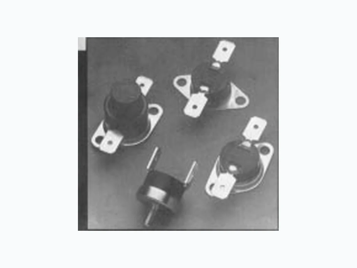
Types R 20/R 22/R 40 are bimetal detectors and temperature regu- lators. Types R 30/R 32 are temperature limiters (manual reset) without tripfree mechanism. The thermal response works via a bimetal snap element electrically connected to the switch contact. The switch system is current insensitive. The thermal switches react only to external thermal effects. Double contacts ensure high switch performance and long service life. The housing, base, and the mounting brackets are voltage-free (Standard version: base and mounting brackets are aluminium-plated steel). Heat transfer occurs directly through the metallic base via convection, radiation and conduction in gaseous and solid media. DIMENSIONS R 20 / R 22 / R 40 R 30 / R 32 Bimetal Cutouts Temperature Regulators Temperature Limiters ADVANTAGES R 20 – high pressure resistance R 22 – high response sensitivity R 30 – numerous applications R 32 – various housings, connections and mounting styles R 40 Types: R20/22/30/32/40 03-03-00 1000-Y135 mounting flange rotating 360 degress mounting flange rotating 360 degress Standard version Standard version CANTHERM
8415 Mountain Sights Avenue • Montreal (Quebec), H4P 2B8, Canada
Tel: (514) 739-3274 • 1-800-561-7207 • Fax: (514) 739-290 E-mail : sales@cantherm.com • Website: www.cantherm.com
Temperature regulation, temperature monitoring, temperature limiting and indication in electric appliances and industrial equipment, machinery and process engineering. Examples: Vacuum cleaners Electrical house- Ironing machines hold appliances Cooking equipment Electronic circuits Dampers Machinery Heat radiators Process engineering Hot water heaters Industrial electric Coffee machines elements Egg boilers Electrical components Electric appliances RESET TEMPERATURES Reset temperature will be between 5 °C and 50 °C below the standard response temperatures. INSTALLATION/MOUNTING INFORMATION Incorporation of the thermo-switch directly in the heat source or attachment to it, is possible without additional insulation. Slightest changes in temperature are conducted through the metallic housing cap directly to the bimetal snap disc of the thermo-switch. This ensu- res that time delays of thermal control systems are kept very small: insensitive to installation posi- tion. The dust-proof and damp-proof construction of the thermo-switch allows various methods of attachment to, and incorporation in appliances. To ensure the best heat transition, the cap respec- tively the mounting bracket should be soldered, rivetted, screwed or spot-welded to the heat source. RESPONSE TEMPERATURE, TOLERANCE, CODE-NO. Nominal temperatures between 50 and 160 °C in 5 °C steps. Nominal temperatures in geometrical series as per DIN 323 in °C. For tolerance, see above – Technical Data. Temperature code – 3 digits Minimum rate of temperature change Type R 20 and R 22 R 30 and R 32 R 40 Voltage rating * 250 V 50–60 Hz 250 V 50–60 Hz * 250 V 50–60 Hz Current rating at cos j = 0.6 6.3 A 6.3 A * 6.3 A Max. load at cos j = 1,0 250 V 50–60 Hz 16.0 A / 20.0 A 20.0 A 16.0 A
110 V 50–60 Hz
60 V DC 6.0 A 6.0 A 42 V DC 7.2 A 7.2 A 6, 12, 24 V DC 8.5 A 8.5 A Contacts Normally closed Normally open * 10 000 * 200 * 30 000 0–170 °C / 16 A Switch operations at IN – * 100 000 50–160 °C / 10 A Contact resistance < 50 m ½ < 50 m½ < 50 m½ Nominal temperature range 0 °C to +170 °C +30 °C to +160 °C + 50 °C to +160 °C but at least ± 3 K ±5 K ± 10 K ± 3 K ±5 K ± 10 K ± 3 K ±5 K ± 10 K Max.permanent temperature * 175 °C * 175 °C * 175 °C Dielectric strength R 20: 3000 V eff50–60 Hz R 30: 3000 V eff50–60 Hz Housing to earth R 22: 4000 V eff50–60 Hz R 32: 4000 V eff50–60 Hz 3000 Veff50–60 Hz Dielectric strength across open contacts 1500 Veff50/60 Hz 1500 V eff50/60 Hz 1500 V eff50/60 Hz Housing material Duroplast Duroplast Duroplast Housing insulation on request on request on request Overall height (mm) R 20 9.5+0.2 R 30 9.5+0.2 R 40 12.0+0.2 R 22 11.5+0.2 R 32 11.5+0.2 TECHNICAL DATA Note: * Approved nominal values. Other specific values on request. Types: R20/22/30/32/40 03-03-00 1000-Y135
OPTIONAL VARIATIONS Terminals, Fixings, Housings Type Descrip- Descrip- Variations tion old tion new Terminals R 20/R 22 R 30/R 32 R 40 A 008 AA008 Flat terminal for screw connection R 20/R 22 R 30/R 32 R 40 A 117 AB 117 6.3 x 0.8 mm terminal R 20/R 22 R 30/R 32 R 40 A 118 AC118 4.8 x 0.8 mm terminal ** R 20/R 22 R 40 A 119 AD119 6.3 x 0.8 mm terminal, * angle 90° R 20/R 22 R 40 A 120 AE120 4.8 x 0.8 mm terminal, ** angle 90° R 20/R 22 R 30/R 32 R 40 A 121 AF121 solder connection * R 20/R 22 R 40 A 122 AG122 solder connection, angle 90° R 20/R 22 R 40 A 123 AH123 flat conductors R 20/R 22 R 40 A 125 AI125 connector pins 4.8 x 0.5 mm R 20/R 22 R 30/R 32 R 40 A128 AK128 screw connection R 20/R 22 R 30/R 32 R 40 A129 AL129 crimp connection R 20/R 22 R 40 A 134 AM134 A119 with inside angled connection 6.3 x 0.8 mm R 20/R 22 R 40 A 135 AN 135 A120 with inside angled connection 4.8 x 0.8 mm R 20/R 22 R 30/R 32 R 40 A 137 AP137 crimp connection/ screw connection R 20/R 22 R 30/R 32 R 40 A 138 AR138 crimp connection/flat terminal R 20/R 22 R 30/R 32 R 40 A139 AS139 screw connection/flat terminal Type Descrip- Descrip- Variations tion old tion new Fixings R 20/R 22 R 30/R 32 R 40 B000 BX000 no mounting bracket R 20/R 22 R 30/R 32 R 40 B 120 BA120 3 hole mounting flange * R 20/R 22 R 30/R 32 R 40 B 214 BB214 mounting bracket, narrow * R 20/R 22 R 30/R 32 R 40 B 215 BC215 mounting bracket-standard ** hole dia. 3.2 mm R 20/R 22 R 30/R 32 R 40 B 217 BD217 brass central mounting * M 5 x 6 mm R 20/R 22 R 30/R 32 R 40 B 218 BE218 brass central mounting M 4 x 8 mm R 20/R 22 R 30/R 32 R 40 B 220 BU220 fixed mounting flange, steel, hole distance 23 mm, angle 0° R 20/R 22 R 30/R 32 R 40 B 221 BG221 fixed mounting flange, steel, hole distance 23 mm, angle 45° R 20/R 22 R 30/R 32 R 40 B 222 BH222 fixed mounting flange, steel, hole distance 23 mm, angle 90° Type Descrip- Descrip- Variations tion old tion new Fixings R 20/R 22 R 30/R 32 R 40 B 223 BI223 fixed mounting flange, steel, * hole distance 23 mm, angle 135° R 20/R 22 R 30/R 32 R 40 B 225 BF225 fixed mounting flange, steel, hole distance 40 mm, narrow, angle 0° R 20/R 22 R 30/R 32 R 40 B 226 BL226 fixed mounting flange, steel, hole distance 40 mm, narrow, angle 45° R 20/R 22 R 30/R 32 R 40 B 227 BM227 fixed mounting flange, steel, ** hole distance 40 mm, narrow, angle 90° R 20/R 22 R 30/R 32 R 40 B 228 BN228 fixed mounting flange, steel, * hole distance 40 mm, narrow, angle 135° R 20/R 22 R 30/R 32 R 40 B 235 BP235 raised flange, hole distance 23 mm, angle 0° R 20/R 22 R 30/R 32 R 40 B 236 BR236 raised flange, hole distance 23 mm, anglel 45° R 20/R 22 R 30/R 32 R 40 B 237 BS237 raised flange, hole distance 23 mm, angle 90° R 20/R 22 R 30/R 32 R 40 B 238 BT238 raised flange, hole distance 23 mm, angle 135° R 20/R 22 R 30/R 32 R 40 B 250 BK250 with rotating mounting flange ** (Standard) hole dia. 3.8 mm R 20/R 22 R 30/R 32 R 40 B 255 BV255 mounting element * Type Descrip- Descrip- Variations tion old tion new Housings R 20/R 22 R 40 G 108 GA108 hexagon threaded sleeve, brass, * with flat terminals 6.3 x 0.8 mm R 30 G128 GB128 without rubber cap, * with reset pin R 32 G 129 GC129 without rubber cap, * with reset pin R 20/R 22 R 40 G 130 GD130 plastic cover horizontal, for leads and cable R 30/R 32 G 135 GE135 housing without reset pin R 20/R 22 R 40 G 145 GF145 hexagon threaded sleeve, brass, with sensor and leads 300 mm R 20/R 22 R 40 G 146 GG146 hard paper sleeve R 20/R 22 R 40 G 147 GH147 voltage-free housing with flange, for leads R 30/R 32 G 408 GI408 cap silicone R 300019 R 30/R 32 G 409 GK409 without reset cap Marking (example) Manufactur = MIC Version = ABXX Version = BD16 Temperature = C029 Type Terminals Ref. letter Housing Standard Fixing Code letter Base 1996 60 °C ±5 K R22 A B X X B D 1 6 C029 ABXX B D 1 6 Indicator for Y ear of manufacture 0-9 (6 = 1996) housing options A-Z Ref. no. for base G for housing 1 = nickel plated steel (standard) Indicator for 2 = stainless steel terminal options A-Z 3 = aluminium, anodised A for terminals 4 = aluminium Indicator for C 0 2 9 fixing option A-Z Code-No. for response B for fixing temp and tolerance Reference to: page 4/5 · see illustrations ** not illustrated MIC ABXX BD16 CO29 E R 20 / R 22 / R 30 / R 32 / R 40 B 255 Mounting element R 20 / R 22 / R 30 / R 32 / R 40 B 120 3 hole mounting flange Types: R20/22/30/32/40 03-03-00 1000-Y135
Types: R20/22/30/32/40 03-03-00 1000-Y135
Types: R20/22/30/32/40 03-03-00 1000-Y135
SPECIAL TEMPERATURE SETTINGS Response temperatures and reset temperatures with specific values and alternative tolerance can be supplied. SPECIAL CONNECTIONS Leads or solid wire from 0.25 mm 2 to 1.0 mm2. Lengths from 40 mm to 10 000 mm, with or without stripping possible. Lead ends with DIN connectors or shrouds. Freon and oil resistant leads, PTFE-, PVF 2, Nomex and Silicone leads available from stock. SPECIAL HOUSINGS When selecting the switch-off temperatures of ther- mostats in special housings or with non-standard mounting, the time delay due to the thermal mass of the housing/mounting has to be considered. Closer tolerances of nominal switch-off temperatu- res and reset temperatures, as well as small diffe- rentials, are also available for small quantities on request. QUALITY STANDARD Production item testing Voltage test, switch function, Nominal response temperature APPROVALS Life expectancy, voltage rating and current rating comply with VDE 0631 or EN 60730, see page 2. Further approvals obtained for many countries. Information on request. NOMINAL RESPONSE TEMPERATURE, TOLERANCE, CODE-NO. Series 10 Series 20 Series 40 Tol. ± 10 % Tol. ± 6 % Tol. ± 3 % °C Code No. °C Code No. °C Code No . Normally closed 100 106 112 118 125 132 140 150 160 161 026 028 030 168 031 033 034 175 036 038 039 182 041 043 044 189 046 048 049 196 100 106 112 118 125 132 140 150 160 162 027 165 029 169 032 172 035 176 037 179 040 183 042 186 045 190 047 193 050 197 100 106 112 118 125 132 140 150 160 170 163 164 166 167 170 171 173 174 177 178 180 181 184 185 187 188 191 192 194 195 198 199 000 007 010 011 012 015 017 022 023 024 025 000 008 131 133 136 139 013 142 016 145 018 147 020 149 152 155 158 000 009 132 134 135 137 138 140 014 141 143 144 146 019 148 021 150 151 153 154 156 157 159 160 Series 10 Series 20 Series 40 Tol. ± 10 % Tol. ± 6 % Tol. ± 3 % °C Code No. °C Code No. °C Code No . Normally open 100 106 112 118 125 132 140 150 160 361 276 278 280 368 281 283 284 375 286 288 289 382 291 293 294 389 296 298 299 396 100 106 112 118 125 132 140 150 160 362 277 365 279 369 282 372 285 376 287 379 290 383 292 386 295 390 297 393 300 397 100 106 112 118 125 132 140 150 160 363 364 366 367 370 371 373 374 377 378 380 381 384 385 387 388 391 392 394 395 398 000 257 260 261 262 265 267 272 273 274 275 000 258 331 333 336 339 263 342 266 345 268 347 270 349 352 355 358 000 259 332 334 335 337 338 340 264 341 343 344 346 269 348 271 350 351 353 354 356 357 359 360 Types: R20/22/30/32/40 03-03-00 1000-Y135 Quan- Type Code Temperature Version Tolerancetity °C
6000 R 22 C 183 100 A 119 ± 6 %
ORDERING INFORMATION
Technical data and other specifications may be altered without prior notice. CANTHERM Tel: (514) 739-3274 • 1-800-561-7207 • Fax: (514) 739-290 E-mail : sales@cantherm.com • Website: www.cantherm.com