

 Download PDF
R2658 HAMAMATSU
Document overview
- PDF pages: 4
Technical content
Page 1
PHOTOMULTIPLIER TUBES
R2658
R2658P (For Photon Counting)
High QE in Near IR Region Due to InGaAs (Cs) Photocathode
For Spectrophotometers with 185 to 1010 nm range,
Fluorescence and Laser Applications and Photon Counting (R2658P)
in the Near Infrared Region, etc.
FEATURES
High QE in Near IR Region ............................... QE 0.13% at 1 µm Wide Wavelength Range ....................................... 185 to 1010 nm Low Dark Current .......................................... 1 nA at 1250 V (Typ.)
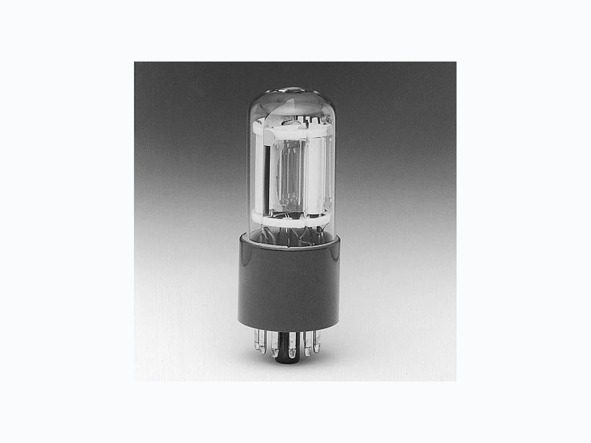
The R2658 and the R2658P are 28 mm (1-1/8 inch) diameter side-on photomultiplier tubes using a newly developed InGaAs semiconductor photocathode. The InGaAs photocathode is sensitive from UV to near IR radiations (as long as over 1010 nm) longer than wavelength limit of GaAs photocathode, and yet offers low dark current. The dark current is 2 orders lower than the commercial S-1 photocathode. Therefore, they are well suited for low light detection in the near IR region including fluorescence lifetime measurements. Time response, gain, and dimensions are identical with the conventional 28 mm (1-1/8 inch) diameter side-on tubes with a GaAs photocathode.
The R2658P is a photon counting version of the R2658 with low dark counts.
GENERAL
| Parameter | Description/Value | Unit | |
|---|---|---|---|
| Spectral Response | 185 to 1010 | nm | |
| Wavelength of Maximum Response | 400 | nm | |
| Photocathode | Material | InGaAs (Cs) | — |
| Minimum Effective Area | 3 × 12 | mm | |
| Window Material | UV glass | — | |
| Dynode | Secondary Emitting Surface | Cu-BeO | — |
| Structure | Circular-cage | — | |
| Number of Stages | 9 | — | |
| Direct Interelectrode Capacitances | Anode to Last Dynode | Approx. 4 | pF |
| Anode to All Other Electrodes | Approx. 6 | pF | |
| Base | 11-pin base JEDEC No. B11-88 | — | |
| Weight | Approx. 45 | g | |
| Suitable Socket (Option) | E678-11A | — | |
| Suitable Socket Assembly (Option) | E717-63 | — | |
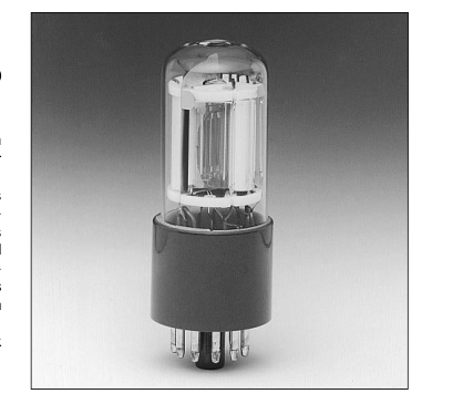
Figure 1: Typical Spectral Response TPMSB0150EA 100
CATHODE RADIANT SENSITIVITY
10
QUANTUM EFFICIENCY
1
0.1
0.01 100 200 300 400 500 600 700 800 900 1000 1100
WAVELENGTH (nm)
Subject to local technical requirements and regulations, availability of products included in this promotional material may vary. Please consult with our sales office. Information furnished by HAMAMATSU is believed to be reliabIe. However, no responsibility is assumed for possible inaccuracies or omissions. Specifications are subject to change without notice. No patent rights are granted to any of the circuits described herein. © 2000 Hamamatsu Photonics K.K.
Page 2
PHOTOMULTIPLIER TUBES R2658, R2658P
MAXIMUM RATINGS (Absolute Maximum Values)
| Parameter | Value | Unit | |
|---|---|---|---|
| Supply Voltage | Between Anode and Cathode | 1500 | Vdc |
| Between Anode and Last Dynode | 250 | Vdc | |
| Average Anode Current A | 1 | µA | |
| Ambient Temperature | -80 to +50 | °C | |
CHARACTERISTICS (at 25°C)
| Parameter | Min. | Typ. | Max. | Unit | ||
|---|---|---|---|---|---|---|
| Cathode Sensitivity | Quantum Efficiency | at 330 nm | — | 14 | — | % |
| at 1000 nm | 0.02 | 0.13 | — | % | ||
| Luminous B | 50 | 100 | — | µA/lm | ||
| Radiant | at 194 nm | — | 20 | — | mA/W | |
| at 254 nm | — | 23 | — | mA/W | ||
| at 400 nm | — | 40 | — | mA/W | ||
| at 633 nm | — | 19 | — | mA/W | ||
| at 852 nm | — | 7.6 | — | mA/W | ||
| at 1000 nm | 0.16 | 1 | — | mA/W | ||
| Red/White Ratio C | 0.25 | 0.4 | — | — | ||
| Anode Sensitivity | Luminous D | 5 | 16 | — | A/lm | |
| Radiant | at 194 nm | — | 3.2 × 10³ | — | A/W | |
| at 254 nm | — | 3.7 × 10³ | — | A/W | ||
| at 400 nm | — | 6.4 × 10³ | — | A/W | ||
| at 633 nm | — | 3.0 × 10³ | — | A/W | ||
| at 852 nm | — | 1.2 × 10³ | — | A/W | ||
| at 1000 nm | — | 1.6 × 10² | — | A/W | ||
| Gain D | — | 1.6 × 10⁵ | — | — | ||
| Anode Dark Current E After 30 minute storage in the darkness | — | 1 | 10 | nA | ||
| Anode Dark Count (for the R2658P) F | — | 50 | 300 | s-1(cps) | ||
| ENI (Equivalent Noise Input) G | — | 1.1 × 10⁻¹⁵ | — | W | ||
| Time Response D | Anode Pulse Rise Time H | — | 2.0 | — | ns | |
| Electron Transit Time J | — | 20 | — | ns | ||
| Anode Current Stability K | Current Hysteresis | — | 2 | — | % | |
| Voltage Hysteresis | — | 2 | — | % | ||
Table 1: Voltage Distribution Ratio
| Electrodes | K | Dy1 | Dy2 | Dy3 | Dy4 | Dy5 | Dy6 | Dy7 | Dy8 | Dy9 | P | |||||||||||
| Distribution Ratio | 1 | 1 | 1 | 1 | 1 | 1 | 1 | 1 | 1 | 1 | ||||||||||||
Supply Voltage= 1250 Vdc K: Cathode, Dy: Dynode, P: Anode
NOTES
A: Averaged over any interval of 30 seconds maximum. B: The light source is a tungsten filament lamp operated at a distribution temperature of 2856 K. Supply voltage is 100 volts between the cathode and all other electrodes connected together as anode. C: Red/white ratio is the quotient of the cathode current measured using a red filter (Toshiba R-68) interposed between the light source and the tube by the cathode current measured with the filter removed under the same condition as Note B. D: Measured with the same light source as Note B and with the voltage distribution ratio shown in Table 1 below. E: Measured with the same supply voltage and the voltage
distribution ratio as Note D after 30 minute storage in the darkness. F: Measured at the voltage producing the gain of 1 × 10⁶ and the voltage distribution ratio shown in table 1 below. The photocathode is cooled at -20 °C. G: ENI is an indication of the photo-limited signal-to-noise ratio. It refers to the amount of light in watts to produce a signal-to-noise ratio of unity in the output of a photomultiplier tube.
2q•ldb•G•∆f ENI = S
where q = Electronic charge (1.60 × 10⁻¹⁹ coulomb) ldb = Anode dark current (after 30 minute storage) in amperes G = Gain ∆f = Bandwidth of the system in hertz. 1 hertz is used. S = Anode radiant sensitivity in amperes per watt at the wavelength of peak response.
H: The rise time is the time for the output pulse to rise from 10 % to 90 % of the peak amplitude when the entire photocathode is illuminated by a delta function light pulse. J: The electron transit time is the interval between the arrival of delta function light pulse at the entrance window of the tube and the time when the anode output reaches the peak amplitude. In measurement, the whole photocathode is illuminated. K. Hysteresis is temporary instability in anode current after light and voltage are applied.
Page 3
Figure 2: Anode Luminous Sensitivity and
Gain Characteristics
TPMSB0151EB
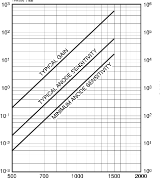
SUPPLY VOLTAGE (V)
Figure 4: Temperature Coefficient
TPMSB0153EA
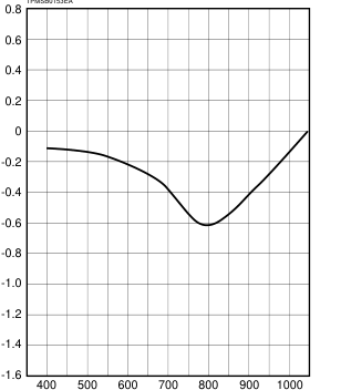
WAVELENGTH (nm)
Figure 3: Typical Time Response
TPMSB0152EA
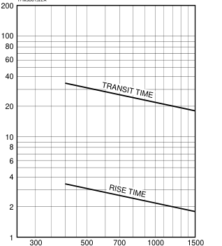
SUPPLY VOLTAGE (V)
Figure 5: Typical Temperature Characteristic of
Dark Current and Dark Count (R2658P)
TPMSB0154EB
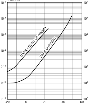
TEMPERATURE (°C)
Page 4
PHOTOMULTIPLIER TUBES R2658, R2658P
Figure 6: Dimensional Outline and Basing Diagram (Unit: mm)
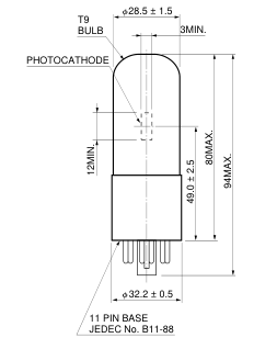
DY6 DY7 DY5 6 5 7
DY4
DY8
4 8
DY3 3
9 DY9
2 10 P
DY2 1 11 K DY1
DIRECTION OF LIGHT
TPMSA0012EC
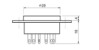
Figure 7: Optional Accessories (Unit: mm)
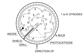
LIGHT
Detail of Tube
(Cross Section of Top View)
TPMSC0040EA
(a) E717-63 (Socket Assembly)
(a) E678-11A (Socket)
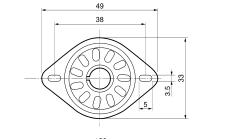
SOCKET
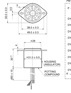
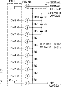
SIGNAL GND SIGNAL OUTPUT RG-174/U (BLACK) POWER SUPPLY GND AWG22 (BLACK)
TACCA0064EA
AWG22 (VIOLET)
TACCA0002EG
Warning-Personal Safety Hazards
Electrical Shock — Operating voltage
applied to this device presents shock hazard.
HOMEPAGE URL http://www.hamamatsu.com
HAMAMATSU PHOTONICS K.K., Electron Tube Center
314-5, Shimokanzo, Toyooka-village, Iwata-gun, Shizuoka-ken, 438-0193, Japan, Telephone: (81)539/62-5248, Fax: (81)539/62-2205 U.S.A.: Hamamatsu Corporation: 360 Foothill Road, P. O. Box 6910, Bridgewater. N.J. 08807-0910, U.S.A., Telephone: (1)908-231-0960, Fax: (1)908-231-1218 Germany: Hamamatsu Photonics Deutschland GmbH: Arzbergerstr. 10, D-82211 Herrsching am Ammersee, Germany, Telephone: (49)8152-375-0, Fax: (49)8152-2658 France: Hamamatsu Photonics France S.A.R.L.: 8, Rue du Saule Trapu, Parc du Moulin de Massy, 91882 Massy Cedex, France, Telephone: (33)1 69 53 71 00, Fax: (33)1 69 53 71 10 United Kingdom: Hamamatsu Photonics UK Limited: Lough Point, 2 Gladbeck Way, Windmill Hill, Enfield, Middlesex EN2 7JA, United Kingdom, Telephone: 44(20)8-367-3560, Fax: 44(20)8-367-6384
North Europe: Hamamatsu Photonics Norden AB: Smidesvägen 12, SE-171-41 SOLNA, Sweden, Telephone: (46)8-509-031-00, Fax: (46)8-509-031-01 Italy: Hamamatsu Photonics Italia: S.R.L.: Strada della Moia, 1/E, 20020 Arese, (Milano), Italy, Telephone: (39)02-935 81 733, Fax: (39)02-935 81 741
TPMS1044E02 MAR. 2000