
DATASHEET SEARCH SITE
Document overview
- Manufacturer or author: Provided By www.digicamel.com(FREE DATASHEET DOWNLOAD SITE)
- PDF pages: 2
Technical content
Features
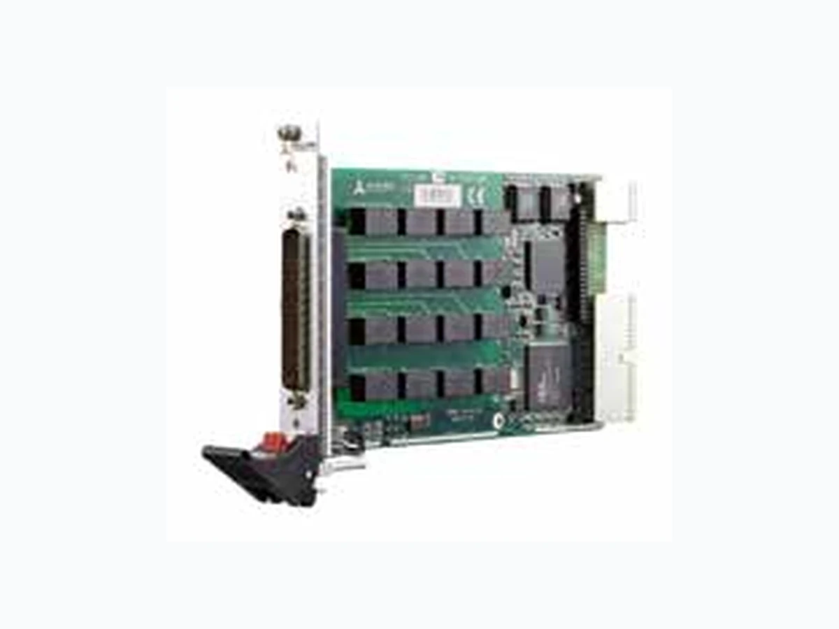
■ PXI specifications Rev. 2.2 compliant ■ 16-CH SPDT (1 Form C) non-latching relays ■ Switching capacity: 3 A switching, 3 A carrying / 220 VDC,
250 VAC
■ 125 operations per second for full settling ■ Onboard 1 k-sample scan list for deterministic scanning ■ Handshaking signals for external instruments synchronization ■ Hardware emergency shutdown with programmable relay safety status ■ 8 auxiliary 3.3 V/TTL digital inputs/outputs with 5 V tolerance 16-CH General-Purpose SPDT Relay Module PXI-7901 Specifications Relay Characteristics ■ Number of channels: 16 ■ Relay type: SPDT (1 Form C), non-latching ■ Switching capacity
- Max. switching current: 3 A
- Max. switching voltage: 220 VDC, 250 VAC
- Max. switching power: 50 VA, 60 W
- Max. carrying current: 3 A ■ Contact resistance: 150 mΩ max. Auxiliary Digital I/O ■ Numbers of channel: 8 inputs/outputs ■ Compatibility: 3.3 V/TTL (5 V tolerant) Safety Functions ■ Emergency shutdown
- Logic level: 3.3 V/TTL (5 V tolerant)
- Active: logic low Switch Introduction General-Purpose (GP) Switches General purpose switches contain several independent relays which are isolated from each other. GP switches are commonly used to connect one input to one output and are usually built with Form A or Form C relays. The normal usage of GP switches is to turn on or turn off devices, such as motors, fans, heaters, and lights. Multiplexers (MUX) In test applications, the quantity of instruments is usually lower due to high cost. Thus, to connect multiple units under test (UUT) with the testing instrument, a multiplexer is always the choice to make the maximum utilization of the instruments. A 1-wire multiplexer routes single-ended signals to one point, and a 2-wire multiplexer selects differential signals. A 4-wire multiplexer is usually used to measure low resistance or RTDs. The instruments which are often used with multiplexer include DMM, digitizer and signal source, such as AWG, to provide both measurement and excitation. Matrix Matrix switches provide the most versatile switching capacity among these function topologies. In the matrix, any input can connect to any output individually or in combination. Unlike the multiplexer, the matrix can connect the source or measurement instrument to multiple UUT s at the same time. Matrix' advantage is the save of wiring. When users want to change the configurations of measure- ment or excitation, users just change the internal connection path, and do not have to manually reconfigure the wiring. T o meet the needs of a wide range of uses in the measurement and automation field, switches come in a variety of types and sizes for versatile applications. It is important to understand the different types of switches available before selecting the most appropriate switch configuration. General Specifications ■ I/O Connector: 62-pin D-sub male ■ Operating temperature: 0˚C to 55˚C (32˚F to 131˚F) ■ Storage temperature: -20˚C to 70˚C (-4˚F to 158˚F) ■ Relative humidity: 5% to 85% non-condensing ■ Power requirements: (when all relays are ON) ■ Dimensions (not including connectors)
- 160 mm x 100 mm (6.24” x 3.9”) Certifications ■ EMC/EMI: CE, FCC Class A ■ Supported Operating System
- Windows 2000/XP ■ Driver and SDK
- LabVIEW , MATLAB, Visual Studio, Visual Studio.NET ■ Software Utility
- ADL-SWITCH for Windows
Ordering Information
T erminal Boards & Cables ■ PXI-7901 16-CH General-Purpose SPDT Relay Module * Failure rate indicates the lower limit of switching capacity of a relay contact at a reliability level of 60% ■ TB-6201-01 General-Purpose Switch T erminal Board with one 62-Pin D-Sub Female Connector for PXI-7901 ■ ACL-10262 62-pin D-sub male/female cable, 1 M (For more information about mating cables, please refer to P3-48.) Switches 2-23 www.adlinktech.com
Updated September 23, 2014. ©2014 ADLINK Technology, Inc. All Rights Reserved. All specifications are subject to change without further notice. Multiplexer One 4x8, T wo 4x4, One 2x16, T wo 2x8, Four 2x4 Source Wire 2-wire Multiplexer One 48x1 One 24x1, T wo 12x1, Four 6x1 One 12x1 Source Wire 1-wire 2-wire 4-wire ■ PXI specifications Rev. 2.2 compliant ■ Configuration determined by terminal board ■ Up to 32 cross-point DPDT (2 Form C) non-latching relays ■ Contact rating
- 2 A switching, 2 A carrying
- 220 VDC, 125 VAC ■ Onboard 1 k-sample scan list for deterministic scanning ■ Hardware emergency shutdown with programmable relay safety status ■ 8 auxiliary 3.3 V/TTL digital inputs/outputs with
5 V tolerance
■ PXI specifications Rev. 2.2 compliant ■ 24-CH DPDT (2 Form C) non-latching relays ■ Switching capacity
- 2 A switching, 2 A carrying
- 220 VDC, 125 VAC ■ Onboard 1 k-sample scan list for deterministic scanning ■ Hardware emergency shutdown with programmable relay safety status 24-CH 2-Wire Multiplexer Module 4x8 2-Wire Matrix Module PXI-7921 PXI-7931 Specifications Relay Characteristics ■ Number of cross points: 32 (2-wire) ■ Relay type: DPDT (2 Form C), non-latching ■ Switching capacity
- Max. switching current: 2 A
- Max. switching voltage: 220 VDC, 125 VAC
- Max. switching power: 60 W
- Max. carrying current: 2 A ■ Contact resistance: 100 mΩ max. Auxiliary Digital I/O ■ Numbers of channel: 8 inputs/outputs ■ Compatibility: 3.3 V/TTL (5 V tolerant) Safety Functions ■ Emergency shutdown
- Logic level: 3.3 V/TTL (5 V tolerant)
- Active: logic low Specifications Relay Characteristics ■ Number of channels: 24 (2-wire) ■ Relay type: DPDT (2 Form C), non-latching ■ Switching capacity
- Max. switching current: 2 A
- Max. switching voltage: 220 VDC, 125 VAC
- Max. switching power: 60 W
- Max. carrying current: 2 A ■ Contact resistance: 100 mΩ max. Safety Functions ■ Emergency shutdown
- Logic level: 3.3 V/TTL (5 V tolerant)
- Active with logic low General Specifications ■ I/O Connector: 62-pin D-sub male ■ Operating temperature: 0˚C to 55˚C (32˚F to 131˚F) ■ Storage temperature: -20˚C to 70˚C (-4˚F to 158˚F) ■ Relative humidity: 5% to 85% non-condensing Certifications ■ EMC/EMI: CE, FCC Class A General Specifications ■ I/O Connector: 62-pin D-sub male ■ Operating temperature: 0˚C to 55˚C (32˚F to 131˚F) ■ Storage temperature: -20˚C to 70˚C (-4˚F to 158˚F) ■ Relative humidity: 5% to 85% non-condensing ■ Power requirements: (when all relays are ON) ■ Dimensions 160 mm x 100 mm (not including connectors) Certifications ■ EMC/EMI: CE, FCC Class A ■ Supported Operating System
- Windows 2000/XP ■ Driver and SDK
- LabVIEW , MATLAB, Visual Studio, Visual Studio.NET ■ Software Utility
- ADL-SWITCH for Windows
T erminal Boards & Cables ■ PXI-7931 4x8 2-Wire Matrix Module * Failure rate indicates the lower limit of switching capacity of a relay contact at a reliability level of 60% ■ TB-6231-01 Multiplexer Switch T erminal Board with One 62-Pin D-Sub Female Connector for PXI-7931 ■ ACL-10262 62-pin D-sub male/female cable, 1 M (For more information about mating cables, please refer to P3-48.) ■ PXI-7921 24-CH 2-Wire Multiplexer Module * Failure rate indicates the lower limit of switching capacity of a relay contact at a reliability level of 60% T erminal Boards & Cables ■ TB-6221-01 Multiplexer Switch T erminal Board with One 62- Pin D-Sub Female Connector for PXI-7921 ■ ACL-10262 62-pin D-sub male/female cable, 1 M (For more information about mating cables, please refer to P3-48.) ■ Supported Operating System
- Windows 2000/XP ■ Driver and SDK
- LabVIEW , MATLAB, Visual Studio, Visual Studio.NET ■ Software Utility
- ADL-SWITCH for Windows Switches 2-24www.adlinktech.com