

 Download PDF
PWS725A BURR-BROWN
Document overview
- PDF pages: 6
Technical content
Page 1
Page 2
SPECIFICATIONS
ELECTRICAL
TA = +25°C, CL = 1µF ceramic, VIN = 15VDC, operating frequency = 800kHz, VOUT = ±15VDC, CIN = 1µF ceramic, IOUT = ±15mA, unless otherwise specified.
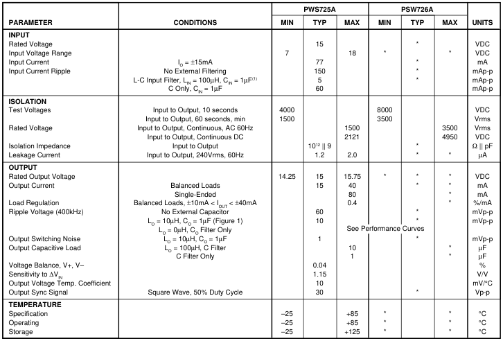
\* Specification same as PWS725A.
PIN CONFIGURATION
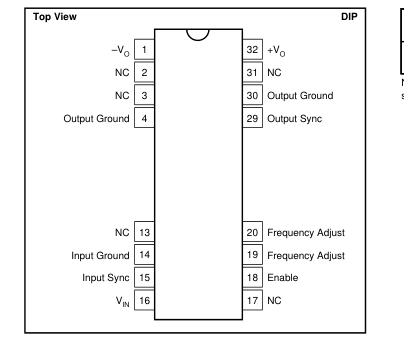
PACKAGE INFORMATION(1)
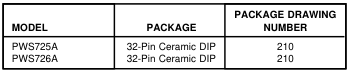
NOTE: (1) For detailed drawing and dimension table, please see end of data sheet, or Appendix D of Burr-Brown IC Data Book.
The information provided herein is believed to be reliable; however, BURR-BROWN assumes no responsibility for inaccuracies or omissions. BURR-BROWN assumes no responsibility for the use of this information, and all use of such information shall be entirely at the user’s own risk. Prices and specifications are subject to change without notice. No patent rights or licenses to any of the circuits described herein are implied or granted to any third party. BURR-BROWN does not authorize or warrant any BURR-BROWN product for use in life support devices and/or systems.
Page 3
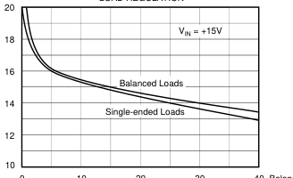
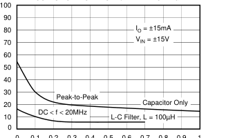
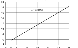
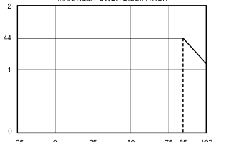
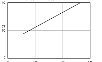
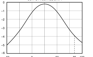
TYPICAL PERFORMANCE CURVES
TA = +25°C, VCC = ±15VDC unless otherwise noted.
LOAD REGULATION
OUTPUT CAPACITANCE vs RIPPLE VOLTAGE
0
0 0.1 0.2 0.3 0.4 0.5 0.6 0.7 0.8 0.9 1
Capacitance (µF)
MAXIMUM POWER DISSIPATION
10 20 30 40 Balanced
20 40 60 80 Single
Output Current (mA)
LINE REGULATION
6 7
75 85 100
0 25 50
–25
Temperature (°C)
INPUT CURRENT vs OUTPUT CURRENT
–50
±15
±30
±45
0
IO (mA)
8 10 12 14 16 18
Input Voltage (V)
OUTPUT VOLTAGE DRIFT
0
50 85 100
Temperature (°C)
Page 4
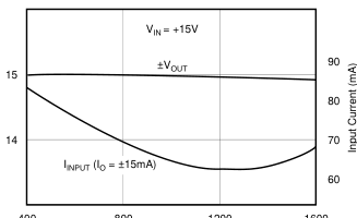
TYPICAL PERFORMANCE CURVES (CONT)
TA = +25°C, VCC = ±15VDC unless otherwise noted.
SYNC FREQUENCY vs INPUT CURRENT AND OUTPUT VOLTAGE
400
800 SYNC Frequency (kHz) (Optional External Control)
THEORY OF OPERATION
The PWS725A and the PWS726A DC/DC converters consist of a free-running oscillator, control and switch driver circuitry, MOSFET switches, a transformer, a bridge rectifier, and filter capacitors together in a 32-pin DIP (0.900 inches nominal) package. The control circuitry consists of current limiting, soft start, frequency adjust, enable, and synchronization features. See Figure 1. In instances where several converters are used in a system, beat frequencies developed between the converters are a potential source of low frequency noise in the supply and ground paths. This noise may couple into signal paths. See Figures 2 and 3 for connection of INPUT SYNC pin. Converters can be syn-
1200
1600
chronized and these beat frequencies avoided. The unit with the highest natural frequency will determine the synchronized running frequency. To avoid excess stray capacitance, the INPUT SYNC pin should not be loaded with more than 50pF. If unused, the INPUT SYNC must be left open. Soft start circuitry protects the MOSFET switches during start up. This is accomplished by holding the gate-to-source voltage of both MOSFET switches low until the freerunning oscillator is fully operational. In addition to that soft start circuitry, input current sensing also protects the MOSFET switches. This current limiting keeps the FET
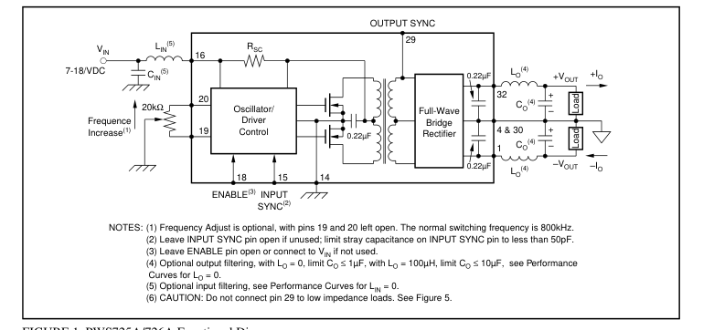
FIGURE 1. PWS725A/726A Functional Diagram.
Page 5
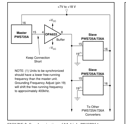
FIGURE 2. Synchronization of Multiple PWS725As or PWS726As from a Master Converter.
switches operating in their safe operating area under fault conditions or excessive loads. When either of these conditions occur, the peak input current exceeds a safe limit. The result is an approximate 5% duty cycle, 300µs drive period to the MOSFET switches. This protects the internal MOSFET switches as well as the external load from any thermal damage. When the fault or excessive load is removed, the converter resumes normal operation. A delay period of approximately 50µs incorporated in the current sensing circuitry allows the output filter capacitors to fully charge after a fault is removed. This delay period corresponds to a filter capacitance of no more than 1µF at either of the output
pins. This provides full protection of the MOSFET switches and also sufficiently filters the output ripple voltage (see specification table). The current sensing circuitry is de- signed to provide thermal protection for the MOSFET switches over the operating temperature range as well. The low thermal resistance for the package (θJC = 10°C/W) ensures safe operation under rated conditions. When these rated conditions are exceeded, the unit will go into its shutdown mode. An optional potentiometer can be connected between the two FREQUENCY ADJUST pins to trim the oscillator operating frequency ±10% (see Figure 4). Care should be taken when trimming the frequency near the low frequency
range. If the frequency is trimmed too low, the peak inductive currents in the primary will trip the input current sensing circuitry to protect the MOSFET switches from these peak inductive currents. The ENABLE pin allows external control of output power. When this pin is pulled low, output power is disabled. Logic thresholds are TTL compatible. When not used, the Enable input may be left open or tied to VIN (pin 16).
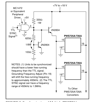
FIGURE 3. Synchronization of Multiple PWS725As or PWS726As from an External TTL Signal.
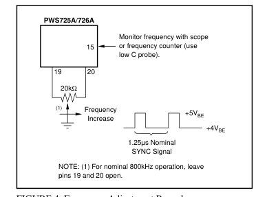
FIGURE 4. Frequency Adjustment Procedure.
OUTPUT CURRENT RATING
The total current which can be drawn from the PWS725A or PWS726A is a function of total power being drawn from both outputs (see Functional Diagram). If one output is not used, then maximum current can be drawn from the other output. If both outputs are loaded, the total current must be limited such that: |IL+| + |IL–| ≤ 80mA It should be noted that many analog circuit functions do not simultaneously draw full rated current from both the positive and negatives supplies. For example, an operational amplifier may draw 13mA from the positive supply under
Page 6
full load while drawing only 3mA from the negative supply. Under these conditions, the PWS725A/726A could supply power for up to five devices (80mA ÷ 16mA ≈ 5). Thus, the PWS725A/726A can power more circuits than is at first apparent.
ISOLATION VOLTAGE RATINGS
Because a long-term test is impractical in a manufacturing situation, the generally accepted practice is to perform a production test at a higher voltage for some shorter period of time. The relationship between actual test conditions and the continuous derated maximum specification is an important one. Burr-Brown has chosen a deliberately conservative one: VDCTEST = (2 X VACrms CONTINUOUS RATING) + 1000V for ten seconds. This choice is appropriate for conditions where system transient voltages are not well defined.(1) Where the real voltages are well-defined or where the isolation voltage is not continuous, the user may choose a less conservative derating to establish a specification from the test voltage.
NOTE: (1) Reference National Electrical Manufacturers Association (NEMA) Standards Parts ICS I-109 and ICS I-111.
OUTPUT SYNC SIGNAL
To allow synchronization of an ISO120 or ISO121 isolation amplifier, the PWS725A and PWS726A have an OUTPUT SYNC signal at pin 29. It should be connected as shown in Figure 5 to keep capacitive loading of pin 29 to a minimum. If output sync is not used, leave pin open.
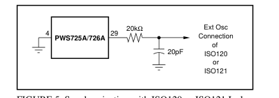
FIGURE 5. Synchronization with ISO120 or ISO121 Isolation Amplifier.