

 Download PDF
PWB_16 ASTRODYNE
Document overview
- PDF pages: 5
Technical content
Page 1

PWB series
PowerBlock Micro-Miniature Modular Switching Power Supplies
2”L x 1”W x 0.6”H
Model Number
Output Voltage
Output Amps
PWB-5000
3.3 VDC
1.25
PWB-5001
5 VDC
1
PWB-5002
12 VDC
0.42
PWB-5003
15 VDC
0.33
PWB-5005
24 VDC
0.23
Single 5 Watt Outputs
3.3VDC to 24VDC
Universal 90 to 264VAC Input
3,000VAC Input to Output Isolation
0 to +50°C Operation
High Efficiency
Output Watts
Size (inches)
4W
1 x 2 x 0.6
5W
1 x 2 x 0.6
5W
1 x 2 x 0.6
5W
1 x 2 x 0.6
5W
1 x 2 x 0.6
Page 2

PWB series
PowerBlock Micro-Miniature Modular Switching Power Supplies
INPUT SPECIFICATIONS
Input Voltage, Nominal
90-264VAC Nominal: 100-240VAC
Input Frequency
47-63 Hz, 50-60Hz Nom.
Inrush Current
20A @ 115VAC, typ 40A @ 230VAC, typ
Leakage Current
<3.5mA @ 264VAC, 50Hz
OUTPUT SPECIFICATIONS
Output Voltage/Current
See Specific Model
Initial Accuracy
+/-1%, typ
Load Regulation
3.3V & 5V:+/-1%, typ
20%-FL
12V, 15V, & 24V:+/-0.5%, typ
Line Regulation
3.3V & 5V:+/-1%, typ 12V, 15V, & 24V:+/-0.5%, typ
Temperature Coefficient
+/-0.03%/°C
Ripple/Noise(20Mhz BW)
200-250mV Pk-Pk, max.
Overvoltage Protection
120-150%, Auto-recovery \*
Hold Up Time
10ms, typ. @ nom. input
Short Circuit Protection
Auto-recovery \*
Over Current Protection
Auto-recovery \*
All specifications are typical at nominal input, full load, and 25DegC unless otherwise noted \* These are stress ratings. Exposure of the devices to any of these conditions may adversely affect long term reliability. Proper operation under conditions other than the standard operating conditions is neither warranteed nor implied.
GENERAL SPECIFICATIONS
Input-Out Isolation
3000VAC
Operating Frequency
100 Khz, fixed, typ
Efficiency @ nom input
71 - 80%, typ (61% typ for 3.3V)
Safety UL/cUL:
UL60950-1 2nd ed./ C22.2 60950-1 2nd ed.
UL-EU:
EN60950-1 2nd ed.
CE:
EN60601-1-2
CB:
IEC60950-1 2nd ed.
EMC
EN55011 Class B
ENVIRONMENTAL SPECIFICATIONS
Oper. Temperature
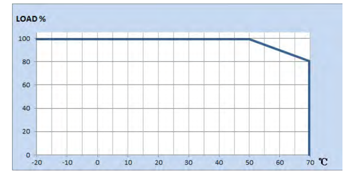
0 to +50°C FL Derate Linearly to 20%L @ 70°C
Relative Humidity
0-95%, Non-Condensing
Storage Temperature
-25 to +71°C \*
MTBF
380,000 Hrs MIL-HDBK 217, Parts Count Method, 25°C, Ground Benign
PHYSICAL SPECIFICATIONS
Case Material
Rynite, 94V-0 Rated
Construction
Encapsulated, Soft Pot
Weight
1.5 oz (42g)
Page 3

PWB series
PowerBlock Micro-Miniature Modular Switching Power Supplies
MECHANICAL SPECIFICATIONS
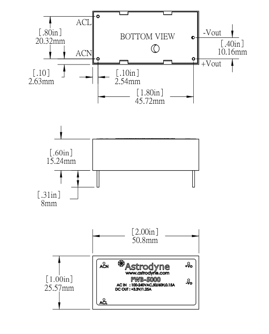
ASTRODYNE PACIFIC CORP.
Parts Name : Parts No : File Name : PWB 5000 A221
Page 4

PWB series
PowerBlock Micro-Miniature Modular Switching Power Supplies
OUTPUT DERATING CURVE
Page 5

PWB series
PowerBlock Micro-Miniature Modular Switching Power Supplies
POWER BLOCK APPLICATION NOTES
Output Noise The figure below ia a sample diagram to reduce Output Ripple and Noise.
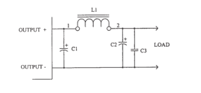
C1 = Electrolytic Capacitor Capacitance = 22uF - 220uF Voltage = Two times rated output voltage
L1 = 3uH - 10uH
C2 = Electrolytic Capacitor Capacitance = 22uF - 47uF Voltage = Two times rated output voltage
C3 = Ceramic Capacitor Capacitance = 0.01uF - 0.1uF Voltage = 50 volt
Notes:
- The use of C1 alone may reduce noise to desired levels, if not use L1, C2 and C3 in addition to C1.
- The figure above is a suggested circuit. Only by trying true application can levels be tested.
EMI The figure below ia a suggested diagram to reduce Electromagnetic Interference (EMI).
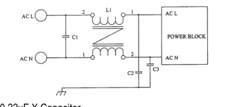
C1 = 0.22uF X Capacitor
L1 = 10mH - 30mH Common Mode, Choke
C2, C3 = 220pF Y Capacitors
Notes:
The diagram above is a recommended circuit, only by trying true application can levels be measured.
Inrush Current
If desired, the use of a Choke, NTC or Inrush Current Limiter may be used to reduce the Inrush Current