

 Download PDF
PTU2000-12-074NA BEL
Document overview
- PDF pages: 9
Technical content
Page 1

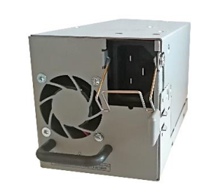
PTU2000-12-074NA is a 2000 W AC to DC, power-factorcorrected (PFC) power supply that converts standard AC power into a main output of +12 VDC.
PTU2000-12-074NA utilizes full digital control architecture for greater efficiency, control and functionality.
- Best-in-class, 80 PLUS “Platinum” efficiency
- Auto-selected input voltage ranges: 90 – 140 VAC, 180 – 264 VAC
- AC input with power factor correction
- 2000 W continuous output power capability
- Always-On 12 V / 3 A standby output
- Air flow direction is Port side intake and Fan side exhaust
- Hot-plug capable
- Parallel operation with active current sharing
- Full digital controls for improved performance
- High density design: 40 W/in3
- Small form factor: 140 x 73.5 x 80 mm (5.51 x 2.89 x 3.15 in)
- Power Management Bus communications protocol for control, programming and monitoring
- Status LED with fault signalling
- Networking Switches
- Servers & Routers
- Telecommunications

Page 2
2
1.
NAME
SPECIFICATION
Input Connector
C22 (according IEC 60320-2-2)
Port Side Intake and Fan side exhaust (N)
Air Flow Direction
Nominal Input Voltage
100 – 127 VAC; 200 – 240 VAC
Output Currents
Io1 = 167 A; Io2 = 3 A
Two Shielded High-Speed Dual Ball Axial Fans: max 25000 RPM
Fan
Acoustic Noise
65LwA dB at 11000 RPM
[Sound Power]
850000 h at 25°C predicted; > 700000 h at 30°C predicted;
MTBF
Calculation according Telcordia SR-332, issue 3, GB (Ground Benign);
200000 h; tested with 30 units; confidence level 90%; 300000 h; tested with 30 units; confidence level > 60%;
DMTBF
tested ambient temperature 50°C;
10 years at 80% nom load / Vi = 230 VAC / 40°C ambient temperature
Capacitor Life Time Expectancy
3 years at 100% nom load / Vi = 180 VAC / 50°C ambient temperature
10000 ft at 715 W (55% load, long term); 50°C; Low Line 6 000 ft at 1300 W (100% load, short term); 50°C; Low Line
Altitude
10000 ft at 1100 W (55% load, long term); 50°C; High Line 6000 ft at 2000 W (100% load, short term); 50°C; High Line
Operating (non-condensing): 5 to 85%
Humidity
Non-Operating: (non-condensing): 5 to 90%
64 kbit, Addressing over A0, A1 and A2
EEPROM
Criterion A for:
- With a single power supply, VIN = 200 VAC, drop 30 % (to 140 VAC) for 500 ms in configuration at 2000 W load (Io1 = 167 A, Io2 = 3 A).
- With VIN = 200 VAC, drop 100% (to 0 VAC) for 20 ms in 1+1 configuration at 2000 W load on
Ride Through
both outputs (Io1 = 167 A, Io2 = 3 A).
- With VIN = 100 VAC, drop 100% (to 0 VAC) for 20 ms in 1+1 configuration at 1300 W load on both outputs (Io1 = 103 A, Io2 = 3 A).
Demonstrated Reliability
300.000 h (RDT)
- Radiated Emissions EN55022/CISPR 22; Class A
- Conducted Emissions EN55022/CISPR 22; Class A
- EN61000-3-2 Harmonics Class A
- EN61000-3-3 Voltage Fluctuations and Flicker
- EN/IEC61000-4-2 ESD; 8 KV Contact, 15 KV Air
- IEC61000-4-3 Radiated Immunity, 10V/m IEC61000-4-4 EFT
EMC
(5 kHz and 100 kHz repetition rates) 2 KV
- IEC61000-4-5 Surge; 2KV CM (12R) and 2KV DM (2R)
- IEC61000-4-6 Conducted Immunity, 10 Vrms
- IEC61000-4-11 Voltage dips, short interruptions and voltage variations immunity tests
- EN61000-4-12 Ring Wave Test; 2KV CM (12R), 2KV DM (12R)

Table 1. PTU2000-12-074NA Specifications

tech.support@psbel.com
Page 3
3
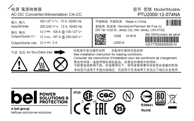
Figure 1. PTU2000-12-074NA Label Details
The address for I2C communication can be configured by pulling address input pins A2, A1 and A0 either to GND (Logic Low) or leave them open (Logic High).
I2C Address1
A2
A1
A0 Controller
EEPROM
0
0
0
0xB0
0xA0
1
0
0
0xB2
0xA2
0
0
1
0xB4
0xA4
1
0
1
0xB6
0xA6
0
1
0
0xB8
0xA8
1
1
0
0xBA
0xAA
0
1
1
0xBC
0xAC
1
1
1
0xBE
0xAE
Table 2. Address and Protocol Encoding
1 The LSB of the address byte is the R/W bit

North America
Asia-Pacific Europe, Middle East
+1 408 785 5200
+86 755 298 85888
+353 61 225 977
© 2019 Bel Power Solutions & Protection
BCD.00936.0_AB
Page 4
4
To achieve best cooling results, sufficient airflow through the supply must be ensured. Do not block or obstruct the airflow at the rear of the supply by placing large objects directly at the output connector. The PTU2000-12-074NA is provided with rear to front airflow, which means the air enters through the DC-output of the supply and leaves at the AC-inlet as shown in Figure 2. The PTU2000-12-074NA supply has been designed for horizontal operation.
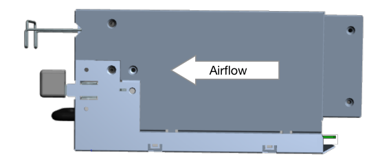
Figure 2. Airflow Direction
The PTU2000-12-074NA provides access via I2C to the measured temperatures of in total 8 sensors within the power supply, see Table 3. The microprocessor is monitoring these temperatures and if warning threshold of one of these sensors is reached it will set fan to maximum speed. If temperatures continue to rise above shut down threshold the main output V1 (or VSB if auxiliary converter is affected) will be disabled. At the same time the warning or fault condition is signalized accordingly through LED, PWOK_H and SMBALERT_L.
TEMPERATURE
DESCRIPTION / CONDITION
SENSOR
Sensor located on control board close to DC end of
Inlet Air Temperature
power supply
Synchronous
Sensor located on secondary side of DC/DC stage
Rectifier Primary Heat Sink
Sensor located on primary heat sink
Output Oring
Sensor located close to output
Element
POWER
MANAGEMENT WARNING SHUT DOWN
BUS
THRESHOLD THRESHOLD
REGISTER
8Dh
77
80
8Eh
100
110
8Fh
100
110
D2h
100
110
Sensor located on secondary side on auxiliary rectifier
Auxiliary Converter
D3h
100
110
Bridge Rectifier
Sensor located on heat sink for AC rectifier
D4h
100
110
Table 3. Temperature Sensors
Recommended maximum power and back pressure (always set at max fan speed) values are listed below:
NOMINAL
MAX INLET
MAX OUTPUT
INPUT VOLTAGE
TEMPERATURE POWER
50 °C
2000 W
200 – 240 VAC
50 °C
1100 W
65 °C
1100 W
50 °C
1300 W
100 – 127 VAC
50 °C
715 W
65 °C
715 W
BACKPRESSURE COMMENTS
425 Pa
Short term condition, 13000 ft (4000 m)
500 Pa
Long term condition, 13000 ft (4000 m)
600 Pa
Short term condition, 6000 ft (1800 m)
435 Pa
Short term condition, 13000 ft (4000 m)
500 Pa
Long term condition, 13000 ft (4000 m)
600 Pa
Short term condition, 6000 ft (1800 m)
Table 4. Output Power and Derating Requirements
Short term condition is defined as a period of not more than 96 h. Component deratings in short term conditions do not have to be met.

tech.support@psbel.com
Page 5
5
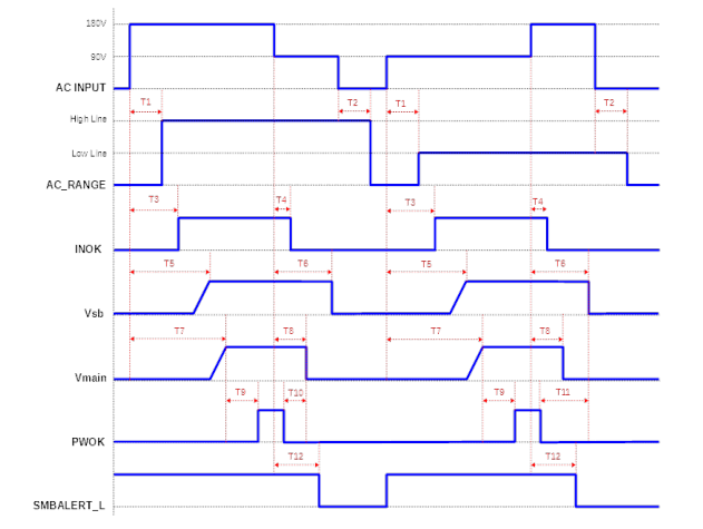
Figure 3. Timing Diagram
NOM
PARAMETER
DESCRIPTION / CONDITION
MIN
MAX UNIT
T1 (Tac_range_lock)
AC INPUT application to Vmain in regulation
- 1000
ms
AC INPUT removal to AC_RANGE reset
T2 (Tac_range_reset)
2000 -
ms
(AC INPUT <= 50V)
T3 (Tinok_on)
AC INPUT application to INOK assert
- - 2500 ms
T4 (Tinok_off)
AC INPUT application to INOK assert
3 - 5 ms
T5 (Tvsb_on_delay)
AC INPUT application to Vsb in regulation
- - 3500 ms
T6 (Tvsb_holdup)
AC INPUT removal to Vsb out of regulation
80 - - ms
T7 (Tvmain_on_delay)
AC INPUT application AC_RANGE lock
- - 300 ms
AC INPUT removal to AC_RANGE reset
T8 (Tvmain_holdup)
1000 - - ms
Note: AC INPUT must be 50 V or less
T9 (Tpwok_on)
AC INPUT application to Vmain in regulation
100 - 4000 ms
T10 (Tpwok_warn_vmain)
PWOK de-assert to Vmain out of regulation
1 - - ms
T11 (Tpwok_warn_vsb)
PWOK de-assert to Vsb out of regulation
20 - - ms
T12 (Tinok_smbalert)
AC INPUT removal to SMBALERT_L assert
- - 25 ms
Tvsb_rise
Vsb rise time (10% - 90%)
1 - 50 ms
Tvmain_rise
Vmain rise time (10% - 90%)
1 - 50 ms
-
Tpson_on
PSON_L active to Vmain in regulation
5
400 ms
Table 5. Timing Table
NOTE: T6 (Tacok_off) on the PTU2000-12-074NA is not relevant due the IN_OK signal pin (S9) is here used for Address A2.

Asia-Pacific Europe, Middle East
North America +1 408 785 5200
+86 755 298 85888
+353 61 225 977
© 2019 Bel Power Solutions & Protection
BCD.00936.0_AB
Page 6
6

m Weight
1.3
kg
JIS G3302 SGCC Hot-dip zinc coated steel, 0.8 mm
Sheet metal
thick, Z12 coating, non-chromated
Table 6. Mechanical Specifications
Dimensions in mm, tolerances acc. ISO 2768 ()-H, unless otherwise stated: 0.5-30: ±0.2; 30-120: ±0.3; 120-400: ±0.5
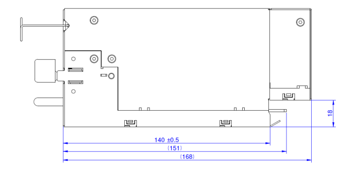
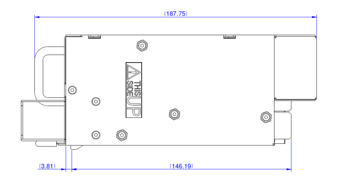
Figure 4. Top and Side View

tech.support@psbel.com
Page 7
7
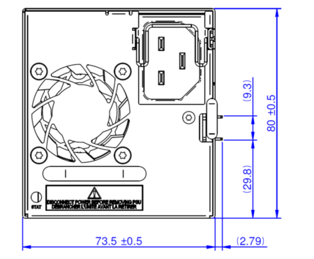
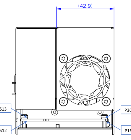
Figure 5. Front View
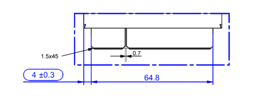
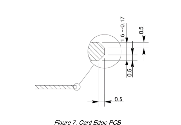
Figure 6. Card Edge PCB

North America
Asia-Pacific Europe, Middle East
+1 408 785 5200
+86 755 298 85888
+353 61 225 977
© 2019 Bel Power Solutions & Protection
BCD.00936.0_AB
Page 8
8
S13
S24
P19
P28
P29
P36
Figure 9. Card Edge PCB Top View
S12
S1
P18 P11
P10
P1
Figure 10. Card Edge PCB Bottom View

tech.support@psbel.com
Page 9
9
PARAMETER
DESCRIPTION / CONDITION
MIN NOM MAX
UNIT
Input connector
IEC 60320-C22
AC Cord Requirement
Wire size
16
AWG
36 Power- + 24 Signal-Pins PCB card edge
Output Connector
Manufacturer: Amphenol
Manufacturer P/N: 10130248-005LF
Mating Output Connector
Bel Power Solutions P/N: ZES.00678
PIN
SIGNAL NAME
DESCRIPTION
MATING SEQUENCE
P1 ~ P10
GND
Power and signal ground (return)
1
P29 ~ P36
GND

S5
NC
NC
1
Analog current share bus
S6
ISHARE
1
For future use, do not connect
S7
Reserved
1
Power supply seated, active-low
S8
PRESENT_L
3
I2C address selection input
S9
A2
2
Power and signal ground (return)
S10 ~ S15
GND
1
Power OK signal output, active-high
S16
PWOK
1
Main output positive sense
S17
V1_SENSE
1
Main output negative sense
S18
V1_SENSE_R
1
SMB Alert signal output, active-low
S19
SMB_ALERT_L
1
Power supply on input, active-low
S20
PSON_L
3
+12 V Standby positive output (as pins S3, S4)
S21, S22
VSB
1
I2C clock signal line
S23
SCL
1
I2C data signal line
S24
SDA
1
Table 7. Output Connector Pin Assignments
NUCLEAR AND MEDICAL APPLICATIONS - Products are not designed or intended for use as critical components in life support systems, equipment used in hazardous environments, or nuclear control systems. TECHNICAL REVISIONS - The appearance of products, including safety agency certifications pictured on labels, may change depending on the date manufactured. Specifications are subject to change without notice.

North America
Asia-Pacific Europe, Middle East
+1 408 785 5200
+86 755 298 85888
+353 61 225 977
© 2019 Bel Power Solutions & Protection
BCD.00936.0_AB