
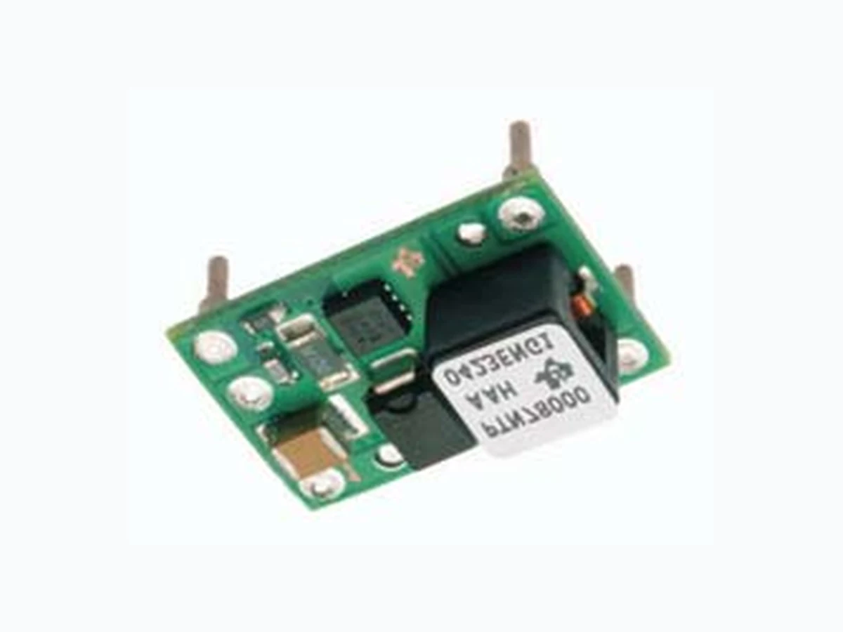
1.5-A Wide Input Adjustable Buck-Boost Switching Regulator datasheet (Rev. B)
Document overview
- Manufacturer or author: Texas Instruments, Incorporated [SLTS246,B]
- PDF pages: 19
Technical content
www.ti.com FEATURES APPLICATIONS
DESCRIPTION
C2* 2 x 4.7 F Ceramic (Required) /c109 C1* 100 F Electrolytic (Required) /c109 C3* 100 F Electrolytic (Required) /c109 GND GND VO PTN78000A (Top View) *See the for capacitor recommendation.Application Information #RSET is required to adjust the output voltage lower than -3 V. See the for values.Application Information STANDARD APPLICATION RSET# 1 %, 0.05 W (Required) PTN78000A SLTS246B–APRIL 2005–REVISED JANUARY 2006 1.5-A, WIDE-INPUT ADJUSTABLE BUCK-BOOST SWITCHING REGULATOR
- General-Purpose, Industrial Controls,• 1.5-A Output Current HVAC Systems, Test and Measurement,• Wide-Input Voltage Medical Instrumentation, AC/DC Adaptors,(7 V to 29 V) Vehicles, Marine, and Avionics
- Wide-Output Voltage Adjust (–15 V to –3 V)
- High Efficiency (Up to 84%)
- Output Current Limit
- Overtemperature Shutdown
- Operating Temperature: –40°C to 85°C
- Surface-Mount Package Available The PTN78000A is a series of high-efficiency, buck-boost integrated switching regulators (ISR), that represent the third generation in the evolution of the PT78NR100 series of products. In new designs, it should be considered in place of the PT78NR100 series of single in-line pin (SIP) products. The PTN78000A is smaller and lighter than its predecessor, and has either similar or improved electrical performance characteristics. The caseless, double-sided package also exhibits improved thermal characteristics, and is compatible with TI's roadmap for RoHS and lead-free compliance. Operating from a wide-input voltage range, the PTN78000A provides high-efficiency, positive-to-negative voltage conversion for loads of up to 1.5 A. The output voltage is set using a single external resistor, and may be set to any value within the range, –15 V to –3 V. The PTN78000A has undervoltage lockout, and is suited to a wide variety of general-purpose applications that operate off 12-V, 24-V, or tightly regulated 28-V dc power. Please be aware that an important notice concerning availability, standard warranty, and use in critical applications of Texas Instruments semiconductor products and disclaimers thereto appears at the end of this data sheet. PRODUCTION DATA information is current as of publication date. Copyright © 2005–2006, Texas Instruments Incorporated Products conform to specifications per the terms of the Texas Instruments standard warranty. Production processing does not necessarily include testing of all parameters.
www.ti.com ABSOLUTE MAXIMUM RATINGS (1) RECOMMENDED OPERATING CONDITIONS PACKAGE SPECIFICATIONS PTN78000A SLTS246B–APRIL 2005–REVISED JANUARY 2006 These devices have limited built-in ESD protection. The leads should be shorted together or the device placed in conductive foam during storage or handling to prevent electrostatic damage to the MOS gates.
ORDERING INFORMATION
PTN78000A (Basic Model) PackageOutput Voltage Part Number Description Pb – free and RoHS Compatible Designator PTN78000AAH Horizontal T/H Yes EUS –15 V to –3 V PTN78000AAS (1)(2) Horizontal SMD No EUT PTN78000AAZ (1)(3) Horizontal SMD Yes EUT (1) Add a T suffix for tape and reel option on SMD packages. (2) Standard optionspecifies Sn/Pb solder ball material. (3) Lead (Pb) - free optionspecifies Sn/Ag solder ball material. over operating free-air temperature range unless otherwise noted all voltages with respect to GND (pin 1), PTN78000A UNIT TA Operating free-air temperature Over V I range –40 to 85 Surface temperature of module body Horizontal SMD (suffix 260Wave solder temperature or pins(5 seconds) AH) Horizontal SMD (suffix 235 °CAS)Surface temperature of module bodySolder reflow temperature or pins Horizontal SMD (suffix 260 AZ) Tstg Storage temperature –40 to 125 (1) Stresses beyond those listed under absolute maximum ratings may cause permanent damage to the device. These are stress ratings only, and functional operation of the device at these or any other conditions beyond those indicated under recommended operating conditions is not implied. Exposure to absolute-maximum-rated conditions for extended periods may affect device reliability. MIN MAX UNIT V I Input voltage 7 32 – |V O|V TA Operating free-air temperature –40 85 °C PO Output power 9W PTN78000A (Suffix AH, AS, and AZ) Weight 2 grams Flammability Meets UL 94 V-O Per Mil-STD-883D, Method 2002.3, 1 ms, ½ sine,Mechanical shock 500 G(1) mounted Horizontal T/H (suffix AH) 20 G (1) Mechanical vibration Mil-STD-883D, Method 2007.2, 20-2000 Hz Horizontal SMD (suffix AS & AZ) 15 G (1) (1) Qualification limit.
www.ti.com
ELECTRICAL CHARACTERISTICS
SLTS246B–APRIL 2005–REVISED JANUARY 2006 operating at 25°C free-air temperature, VI =1 2V ,VO =– 5V ,IO =I O (max), C1 = 100μF, C2 =2 x4 . 7μF, C3 = 100μF (unless otherwise noted) PARAMETER TEST CONDITIONS MIN TYP MAX UNIT IO Output current T A = 85°C, natural convection airflow A VO =– 5V 0 . 1 1 . 5 (1) VO = –15 V 7 17 (2) VO = –12 V 7 20 (2) VI Input voltage range Over I O range V VO =– 5V 7 2 7 (2) Set-point voltage tolerance TA = 25°C ±2% (3) Temperature variation –40°C to 85°C ±0.5% Line regulation Over V I range ±10 mVVO Load regulation Over I O range ±10 mV Total output voltage Includes set point, line, load ±3% (3) variation –40 < T A < 85°C Output voltage adjust 7 V ≤ VI ≤ (32 – |VO|) V –15 –3VO Adj Vrange VI =1 2V ,RSET =1 0 0Ω,V O = –15 V 83% VI =1 2V ,RSET =2k Ω,V O = –12 V 84% η Efficiency VI =1 2V ,RSET =2 8 . 7kΩ,V O = –5 V 82% VI =1 2V ,RSET =2 2 1kΩ,V O = –3.3 V 77% Output voltage ripple 20-MHz bandwidth 2% V O V(PP) IO( L I M ) Current limit threshold ΔVO = –50 mV 3.2 A 1A /μs load step from 50% to 100% IOmax Transient response Recovery time 200 μs VO over/undershoot 1 %V O FS Switching frequency Over V I and IO ranges 440 550 660 kHz UVLO Undervoltage lockout V I increasing 5.5 V Ceramic 9.4 (4) μF CI External input capacitance Nonceramic 100 (4) μF Ceramic 200 μF External outputCO Nonceramic 100 (5) 1,000 μFcapacitance Equivalent series resistance (nonceramic) 14 (6) mΩ Per Telcordia SR-332, 50% stress,MTBF Calculated reliability 8.9 106 HrsTA = 40°C, ground benign (1) The maximum output current is 1.5 A or the maximum output power is 9 W, whichever is less. (2) The maximum input voltage is limited and defined to be (32 – |VO|) volts. (3) The set-point voltage tolerance is affected by the tolerance and stability of RSET. The stated limit is unconditionally met if RSET has a tolerance of 1% with 100 ppm/°C or better temperature stability. (4) A 100- μF electrolytic capacitor and two 4.7-μF ceramic capacitors are required across the input (VI and GND) for proper operation. Locate the ceramic capacitance close to the module. (5) 100 μF of output capacitance is required for proper operation. See the application information for further guidance. (6) This is the typical ESR for all the electrolytic (nonceramic) capacitance. Use 17 mΩ as the minimum when using maximum ESR values to calculate.
www.ti.com PIN ASSIGNMENT PTN78000A (Top View) PTN78000A SLTS246B–APRIL 2005–REVISED JANUARY 2006 TERMINAL FUNCTIONS TERMINAL I/O DESCRIPTION NAME NO. The negative output voltage power node with respect to the GND node. It is also the reference for theVO 1O VO Adjust control inputs. VI 2 I The positive input voltage power node to the module, which is referenced to common GND. N/C 3 This pin is active and must be isolated from any electrical connection. A 1% resistor must be connected between pin 1 and pin 4 to set the output voltage of the module lower than –3 V. If left open-circuit, the output voltage defaults to –3 V. The temperature stability of the resistorVO Adjust 4 I should be 100 ppm/°C (or better). The set-point range is –15 V to –3 V. The standard resistor value for a number of common output voltages is provided in the application information. GND 5 I/O The common ground connection for the VI and VO power connections.
200 LFM
100 LFM
Figure 1. Figure 2. Figure 3. Figure 4. Figure 5. Figure 6. converter. Applies toFigure 1, Figure 2, andFigure 3. operating temperatures. Derating limits apply to modules soldered directly to a 100 mm x 100 mm, double-sided PCB with 2 oz. copper. the mechanical specification for more information. Applies toFigure 4,Figure 5, andFigure 6.
Figure 7. Figure 8. Figure 9. Figure 10. Figure 11. Figure 12. converter. Applies toFigure 7, Figure 8, andFigure 9. operating temperatures. Derating limits apply to modules soldered directly to a 100-mm x 100-mm, double-sided PCB with 2 oz. copper. the mechanical specification for more information. Applies toFigure 10, Figure 11, andFigure 12.
Figure 13. Figure 14. Figure 15. converter. Applies toFigure 13, Figure 14, andFigure 15. operating temperatures. Derating limits apply to modules soldered directly to a 100-mm x 100-mm, double-sided PCB with 2 oz. copper. the mechanical specification for more information. Applies toFigure 16.
www.ti.com
APPLICATION INFORMATION
Adjusting the Output Voltage of the PTN78000A Wide-Output Adjust Power Modules General R = 54.9 kSET /c87/c1801.25 V ||V -3VO - 5.62 k/c87 Input Voltage Considerations GND VO PTN78000A Adj GND VO VI VI GND C1 C2 RSET 0.05 W PTN78000A SLTS246B–APRIL 2005–REVISED JANUARY 2006 A resistor must be connected directly between theVO Adjust control (pin 4) and the outputvoltage (pin 7) to set the output voltage lower than –3 V. The adjustment range is from –15 V to –3 V. If pin 4 is left open, the output voltage defaults to the highest value, –3 V. Table 1 gives the standard resistor value for a number of common voltages, and with the actual output voltage that the value produces. For other output voltages, the resistor value can either be calculated using the following formula, or simply selected from the range of values given inTable 2. Figure 17 shows the placement of the required resistor. The PTN78000A is a buck-boost switching regulator. In order that the output remains in regulation, the input voltage must not exceed the output by a maximum differential voltage. For satisfactory performance, the maximum operating input voltage is (32 - |V O|) volts. As an example,Table 1gives the operating input voltage range for the common output bus voltages. In addition, the Electrical Characteristics define the available output voltage adjust range for various input voltages. Table 1. Standard Values of Rset for Common Output Figure 17. VO Adjust Resistor Placement
Table 2. Output Voltage Set-Point Resistor Values
www.ti.com CAPACITOR RECOMMENDATIONS FOR THE PTN78000 WIDE-OUTPUT Input Capacitor Output Capacitor Ceramic Capacitors Tantalum Capacitors Capacitor Table PTN78000A SLTS246B–APRIL 2005–REVISED JANUARY 2006 ADJUST POWER MODULES The minimum requirements for the input bus is 100μF of nonceramic capacitance and 9.4μF( 2x4 . 7μF) of ceramic capacitance, in either an X5R or X7R temperature characteristic, and 100μF of electrolytic capacitance. Ceramic capacitors should be located within 0.5 inch (1,27 cm) of the regulator's input pins. Electrolytic capacitors should be used at the input in addition to the required ceramic capacitance. The minimum ripple current rating for any nonceramic capacitance must be at least 250 mA rms. The ripple current rating of electrolytic capacitors is a major consideration when they are used at the input. This ripple current requirement can be reduced by placing more ceramic capacitors at the input, in addition to the minimum required 9.4μF. Tantalum capacitors are not recommended for use at the input bus, as none were found to meet the minimum voltage rating of 2 × (maximum dc voltage + ac ripple). The 2× rating is standard practice for regular tantalum capacitors to ensure reliability. Polymer-tantalum capacitors are more reliable and are available with a maximum rating of typically 20 V. These can be used with input voltages up to 16 V. The minimum capacitance required to ensure stability is a 100μF. Either ceramic or electrolytic-type capacitors can be used. The minimum ripple current rating for the nonceramic capacitance must be at least 200 mA rms. The stability of the module and voltage tolerances is compromised if the capacitor is not placed near the output bus pins. A high-quality, computer-grade electrolytic capacitor should be adequate. A ceramic capacitor can be also be located within 0.5 inch (1,27 cm) of the output pin. For applications with load transients (sudden changes in load current), the regulator response improves with additional capacitance. Additional electrolytic capacitors should be located close to the load circuit. These capacitors provide decoupling over the frequency range, 2 kHz to 150 kHz. Aluminum electrolytic capacitors are suitable for ambient temperatures above 0°C. For operation below 0°C, tantalum or Os-Con-type capacitors are recommended. When using one or more nonceramic capacitors, the calculated equivalent ESR should be no lower than 14 mΩ (17 mΩ using the manufacturer's maximum ESR for a single capacitor). A list of recommended capacitors and vendors are identified inTable 3. Above 150 kHz, the performance of aluminum electrolytic capacitors becomes less effective. To further reduce the reflected input ripple current, or the output transient response, multilayer ceramic capacitors must be added. Ceramic capacitors have low ESR, and their resonant frequency is higher than the bandwidth of the regulator. When placed at the output, their combined ESR is not critical as long as the total value of ceramic capacitance does not exceed 200μF. Tantalum-type capacitors may be used at the output, and are recommended for applications where the ambient operating temperature can be less than 0°C. The AVX TPS, Sprague 593D/594/595, and Kemet T495/T510/T520 capacitors series are suggested over many other tantalum types due to their rated surge, power dissipation, and ripple current capability. As a caution, many general-purpose tantalum capacitors have considerably higher ESR, reduced power dissipation, and lower ripple current capability. These capacitors are also less reliable as they have lower power dissipation and surge current ratings. Tantalum capacitors that do not have a stated ESR or surge current rating are not recommended for power applications. When specifying Os-Con and polymer-tantalum capacitors for the output, the minimum ESR limit is encountered well before the maximum capacitance value is reached. The capacitor table, Table 3, identifies the characteristics of capacitors from various vendors with acceptable ESR and ripple current (rms) ratings. The recommended number of capacitors required at both the input and output buses is identified for each capacitor type. This is not an extensive capacitor list. Capacitors from other vendors are available with comparable specifications. Those listed are for guidance. The rms rating and ESR (at 100 kHz) are critical parameters necessary to ensure both optimum regulator performance and long capacitor life.
Table 3. Recommended Input/Output Capacitors regulator at a higher input voltage, select a capacitor with the next higher voltage rating. voltage, select a capacitor with a higher voltage rating. (3) Not recommended (N/R). The voltage rating does not meet the minimum operating limits in most applications. component to operate at a higher input voltage.
waveforms were measured with a 1.5-A resistive load. Figure 18. Power-Up Waveforms power up. Below the UVLO threshold, the module is held off. derated limits, for the worst-case operating conditions of output current, ambient temperature, and airflow.
various filters and design techniques found to be successful in reducing both input and output ripple/noise. capacitor reduces the output ripple/noise by 10% to 30% for modules with a rated output current of less than 3 A. the input power pins, reduces reflected conducted ripple/noise by 20% to 30%. A. See specifications for required value and type. B. See Application Informationfor suggested value and type. Figure 19. Adding High-Frequency Bypass Capacitors to the Input and Output
1 MHz
A. See specifications for required value and type. B. See Application Informationfor suggested value and type. C. Recommended for applications with load transients. Figure 20. Adding π Filters (IO≤ 3A ) Figure 21. π-Filter Attenuation vs. Load Current
www.ti.com 11-Nov-2025 PACKAGING INFORMATION Orderable part number Status (1) Material type (2) Package | Pins Package qty | Carrier RoHS (3) Lead finish/ Ball material (4) MSL rating/ Peak reflow (5) Op temp (°C) Part marking (6) PTN78000AAH Active Production Through-Hole Module (EUS) | 5 56 | TIW TRAY In-Work SN N/A for Pkg Type -40 to 85 PTN78000AAH.B Active Production Through-Hole Module (EUS) | 5 56 | TIW TRAY In-Work SN N/A for Pkg Type -40 to 85 PTN78000AAS Active Production Surface Mount Module (EUT) | 5 49 | TIW TRAY No SNPB Level-1-235C-UNLIM/ Level-3-260C-168HRS -40 to 85 PTN78000AAS.B Active Production Surface Mount Module (EUT) | 5 49 | TIW TRAY No SNPB Level-1-235C-UNLIM/ Level-3-260C-168HRS -40 to 85 PTN78000AAST Active Production Surface Mount Module (EUT) | 5 250 | SMALL T&R No SNPB Level-1-235C-UNLIM/ Level-3-260C-168HRS -40 to 85 PTN78000AAST.B Active Production Surface Mount Module (EUT) | 5 250 | SMALL T&R No SNPB Level-1-235C-UNLIM/ Level-3-260C-168HRS -40 to 85 PTN78000AAZ Active Production Surface Mount Module (EUT) | 5 49 | TIW TRAY Exempt SNAGCU Level-3-260C-168 HR -40 to 85 PTN78000AAZ.B Active Production Surface Mount Module (EUT) | 5 49 | TIW TRAY Exempt SNAGCU Level-3-260C-168 HR -40 to 85 PTN78000AAZT Active Production Surface Mount Module (EUT) | 5 250 | SMALL T&R Exempt SNAGCU Level-3-260C-168 HR -40 to 85 PTN78000AAZT.B Active Production Surface Mount Module (EUT) | 5 250 | SMALL T&R Exempt SNAGCU Level-3-260C-168 HR -40 to 85 (1) Status: For more details on status, see our product life cycle. (2) Material type: When designated, preproduction parts are prototypes/experimental devices, and are not yet approved or released for full production. Testing and final process, including without limitation quality assurance, reliability performance testing, and/or process qualification, may not yet be complete, and this item is subject to further changes or possible discontinuation. If available for ordering, purchases will be subject to an additional waiver at checkout, and are intended for early internal evaluation purposes only. These items are sold without warranties of any kind. (3) RoHS values: Yes, No, RoHS Exempt. See the TI RoHS Statement for additional information and value definition. (4) Lead finish/Ball material: Parts may have multiple material finish options. Finish options are separated by a vertical ruled line. Lead finish/Ball material values may wrap to two lines if the finish value exceeds the maximum column width. Addendum-Page 1
www.ti.com 11-Nov-2025 (5) MSL rating/Peak reflow: The moisture sensitivity level ratings and peak solder (reflow) temperatures. In the event that a part has multiple moisture sensitivity ratings, only the lowest level per JEDEC standards is shown. Refer to the shipping label for the actual reflow temperature that will be used to mount the part to the printed circuit board. (6) Part marking: There may be an additional marking, which relates to the logo, the lot trace code information, or the environmental category of the part. Multiple part markings will be inside parentheses. Only one part marking contained in parentheses and separated by a "~" will appear on a part. If a line is indented then it is a continuation of the previous line and the two combined represent the entire part marking for that device. Important Information and Disclaimer:The information provided on this page represents TI's knowledge and belief as of the date that it is provided. TI bases its knowledge and belief on information provided by third parties, and makes no representation or warranty as to the accuracy of such information. Efforts are underway to better integrate information from third parties. TI has taken and continues to take reasonable steps to provide representative and accurate information but may not have conducted destructive testing or chemical analysis on incoming materials and chemicals. TI and TI suppliers consider certain information to be proprietary, and thus CAS numbers and other limited information may not be available for release. In no event shall TI's liability arising out of such information exceed the total purchase price of the TI part(s) at issue in this document sold by TI to Customer on an annual basis. Addendum-Page 2
IMPORTANT NOTICE AND DISCLAIMER TI PROVIDES TECHNICAL AND RELIABILITY DATA (INCLUDING DATASHEETS), DESIGN RESOURCES (INCLUDING REFERENCE DESIGNS), APPLICATION OR OTHER DESIGN ADVICE, WEB TOOLS, SAFETY INFORMATION, AND OTHER RESOURCES “AS IS” AND WITH ALL FAULTS, AND DISCLAIMS ALL WARRANTIES, EXPRESS AND IMPLIED, INCLUDING WITHOUT LIMITATION ANY IMPLIED WARRANTIES OF MERCHANTABILITY, FITNESS FOR A PARTICULAR PURPOSE OR NON-INFRINGEMENT OF THIRD PARTY INTELLECTUAL PROPERTY RIGHTS. These resources are intended for skilled developers designing with TI products. You are solely responsible for (1) selecting the appropriate TI products for your application, (2) designing, validating and testing your application, and (3) ensuring your application meets applicable standards, and any other safety, security, regulatory or other requirements. These resources are subject to change without notice. TI grants you permission to use these resources only for development of an application that uses the TI products described in the resource. Other reproduction and display of these resources is prohibited. No license is granted to any other TI intellectual property right or to any third party intellectual property right. TI disclaims responsibility for, and you fully indemnify TI and its representatives against any claims, damages, costs, losses, and liabilities arising out of your use of these resources. TI’s products are provided subject to TI’s Terms of Sale, TI’s General Quality Guidelines, or other applicable terms available either on ti.com or provided in conjunction with such TI products. TI’s provision of these resources does not expand or otherwise alter TI’s applicable warranties or warranty disclaimers for TI products. Unless TI explicitly designates a product as custom or customer-specified, TI products are standard, catalog, general purpose devices. TI objects to and rejects any additional or different terms you may propose. IMPORTANT NOTICE Copyright © 2025, Texas Instruments Incorporated Last updated 10/2025