


 Download PDF
DATASHEET SEARCH SITE
Document overview
- PDF pages: 4
Technical content
Page 1

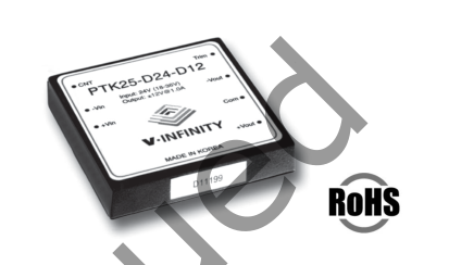
DESCRIPTION: dc-dc converter
PART NUMBER: PTK25

Page 2

DESCRIPTION: dc-dc converter
PART NUMBER: PTK25
INPUT
parameter conditions/description
min nom max units
input voltage range
18 24 36 VDC
36 48 72 VDC
remote on/off control output turn-on3
2.5V (open) 5.5V
output turn-off
0V (short) 0.8V
switching frequency constant
300
KHz
NOTE: 3 output defaults to “on” when there is no connection to the “CNT” pin.
OUTPUT
parameter
conditions/description
min nom max
units
output trim range
with external trim resistors
-5%
+5%
set point accuracy
single output
-2%
+2%
dual output
-3%
+3%
line regulation
single output models
-0.25%
+0.25%
(low line to high line)
dual output models
-2.5%
+2.5%
triple: main output (Vout)
-0.25%
+0.25%
auxillary outputs (+Vaux / -Vaux)
-5%
+5%
load regulation
single output models- no load to full load
-0.25%
+0.25%
dual output models- balanced loads
-2.5%
+2.5%
triple: main output (Vout)
-0.25%
+0.25%
auxillary outputs (+Vaux / -Vaux)- with 10%
-5%
+5%
load on Vout and balanced loads on+Vaux and -Vaux converters will not be damaged if loading conditions are less than minimum specified loads,
minimum load
but regulation specs may not be met4
ripple and noise
see chart
NOTE: 4 single output: no min. load required, dual: 10%, triple: balanced loads
PROTECTION
parameter
conditions/description
min nom max units
continuous auto recovery 5
over-current
105%
135%
internally zener clamped 5
over-voltage
110%
140%
NOTE: 5 continuous operation in a protected state may compromise long-term reliability.
GENERAL
parameter
conditions/description
min nom max units
efficiency
typical at full load
77%
83%
isolation voltage
input/case, input/output, output/case
500
VAC
insulation resistance
at 500 VDC
100M
Ohms
approved to UL60950(E222889), CSA C22.2 No. 60950, TUV EN60950 (single output only)
agency standards case material
Zn
material flammability
94 V-0
weight
80
grams
(2.82)
(ounces)
MTBF
MIL-HDBK-217F
470k
hours
operating temperature regular models - see derating curve.
-20
+71 °C
extended temperature models
-40
+85 °C
storage temperature
-40
+105 °C
humidity
operating (non-condensing)
5%
95% RH
washability
not intended for aqueous wash
Page 3

DESCRIPTION: dc-dc converter
PART NUMBER: PTK25
DIMENSIONS (mm)
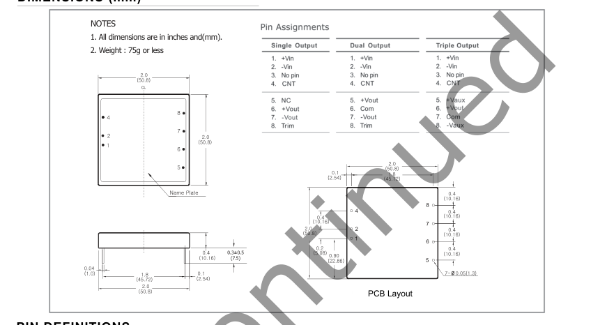
PIN DEFINITIONS

DERATING CURVES
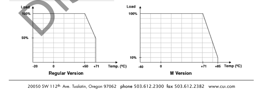
Page 4

DESCRIPTION: dc-dc converter
PART NUMBER: PTK25
APPLICATION NOTES
1. OUTPUT TRIMMING
The output voltages are preset to nominal values as indicated by the models table at the factory. If desired, the output voltage may optionally be trimmed to a different value (+/- 10%) with external resistors and/or potentiometer as shown below.

To trim the output voltage with fixed resistors, the output voltage can be calculated as follows.
+Vo
+Vin
Trim
R load
R trim-up
-Vin
-Vo
Trim-Up
FIGURE 2: TRIM-UP VOLTAGE SETUP
Vr · R1 · R2
Rtrim_up=
R2 · (Vo - Vr) - Vr · R1
The value of Rtrim-up is defined as: Where: Rtrim-up is the external resistor in KΩ. Vo is the desired output voltage. R1 and R2 and Vr are internal to the unit and are defined in Table 1. For example to trim up the PTK25-D5-D12 up by 5% to 25.2 V, Rtrim-up is calculated
as follows:
Vo = 25.2 / R1 = 21 KΩ / R2 = 2.43 KΩ / Vr = 2.5
2.5 · 21 · 2.43
Rtrim_up =
= 47.94 KΩ
2.43 · (25.2 - 2.5) - 2.5 · 21
+Vo
+Vin
R trim-down
Trim
R load
-Vin
-Vo
Trim-Down
FIGURE 3: TRIM-DOWN VOLTAGE SETUP
(Vo - Vr) · R1 · R2
Rtrim_down=
Vr · R1 - (Vo - Vr) · R2
The value of Rtrim-down is defined as: Where: Rtrim-down is the external resistor in KΩ. Vo is the desired output voltage. R1 and R2 and Vr are internal to the unit and are defined in Table 1. For example to trim down the PTK25-D5-D12 down by 5% to 22.8 V, Rtrim-down is calculated
as follows:
Vo = 22.8 / R1 = 21 KΩ / R2 = 2.43 KΩ / Vr = 2.5
(22.8 - 2.5) · 21 · 2.43
Rtrim_down=
= 326.68 KΩ
2.5 - 2.1 (22.8 - 2.5) · 2.43
| Model | R1 (KΩ) | R2 (KΩ) | Vr (V) |
| PTK25-DXX-S3.3 | 1.13 | 0.68 | 1.25 |
| PTK25-DXX-S5 | 2.43 | 2.43 | 2.5 |
| PTK25-DXX-S12 | 9.31 | 2.43 | 2.5 |
| PTK25-DXX-S15 | 12.1 | 2.4 | 2.5 |
| PTK25-DXX-D5 | 7.32 | 2.43 | 2.5 |
| PTK25-DXX-D12 | 21 | 2.43 | 2.5 |
| PTK25-DXX-D15 | 26.7 | 2.43 | 2.5 |