
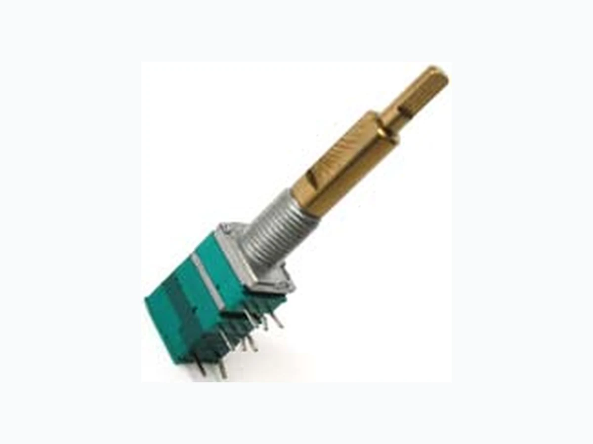
PTH90 BOURNS
Document overview
- Manufacturer or author: Provided By www.digicamel.com(FREE DATASHEET DOWNLOAD SITE)
- PDF pages: 2
Technical content
Features
■ Carbon element ■ Assortment of resistance tapers ■ Variety of shaft lengths ■ Dual gang element ■ Flatted, slotted and knurled shaft styles ■ Center detent option PTH90 Series Dual Concentric Shaft Panel Control w/Rotary Switch *RoHS Directive 2002/95/EC Jan 27, 2003 including Annex. Specifi cations are subject to change without notice. Customers should verify actual device performance in their specifi c applications.
Electrical Characteristics
Standard Resistance Tolerance End Resistance Insulation Resistance @ 250 VDC Dielectric Withstanding Voltage ....300 VAC Power Rating Environmental Characteristics Operating Temperature Range Mechanical Characteristics Soldering Condition one mounting nut supplied with each potentiometer Switch Characteristics Dielectric Strength Insulation Resistance Bushing to Terminals @ 250 VAC Switch Terminals @ 50 VAC Product Dimensions (Shown with Flatted Shaft) DIMENSIONS: MM (INCHES) Mounting Hole Detail Knurled Shaft L1 L2 30.0 (1.181) 20.0 (.787) 35.0 (1.378) 25.0 (.984) Locating Lug Detail 2.0 ± 0.1 (0.079 ± 0.004) Y Y XX 0.8 ± 0.2 (0.315 ± 0.008) 6.0 ± 0.2 (0.236 ± 0.008) 5.0 (0.197) 6.5 (0.256) 5.0 (0.197) 5.0 (0.197) 1.0 +0.1/-0 (0.039 +0.004/-0) DIA. MOUNTING SURFACE 8 PLCS. Additional Shaft Styles 60 ° 8.0 (0.315) SLOTTING ANGLE OF INNER SHAFT NOT SPECIFIED OUTER SHAFT SHOWN IN FULL CCW POSITION 5.0 (0.197) 1.0 (0.039)3.0 (0.118) C1C0.5 M9 X 0.75 (0.030) 1.0 (0.039) 10.0 (0.394) 6.0 (0.236)DIA. 8.0 (0.315) 9.0 (0.354) 8.0 (0.315) DIA. L1 L2 30.0 (1.181) 20.0 (.787) 35.0 (1.378) 25.0 (.984) Slotted Shaft 60 ° 5.0 (0.197) 3.0 (0.118) C0.5C0.5 M9 X 0.75 (0.030) 1.5 (0.059) 4.7 (0.185)DIA. 6.7 (0.264) DIA. 8.0 (0.315) SLOTTING ANGLE OF INNER SHAFT NOT SPECIFIED OUTER SHAFT SHOWN IN FULL CCW POSITION 10.0 (0.394) 8.0 (0.315) L1 L2 35.0 (1.378) 21.0 (.827) 40.0 (1.575) 26.0 (1.024) *RoHS COMPLIANT
Specifi cations are subject to change without notice. Customers should verify actual device performance in their specifi c applications. PTH90 Series Dual Concentric Shaft Panel Control w/Rotary Switch Tapers 01 0 100 100 A Series Tapers Terminal 1 Output Voltage across Terminals 1-2 Input Voltage across Terminals 1-3 X 100 (%) Terminal 3Rotational Travel (%) (05A);A1 (10A);A2 (15A);A3 (20A);A4 (25A);A5 (30A);A6 01 0 100 100 B Series Tapers Terminal 1 Output Voltage across Terminals 1-2 Input Voltage across Terminals 1-3 X 100 (%) Terminal 3Rotational Travel (%) (4B);B (3B);B3 (2B);B2 (1B);B1 (5B);B5 01 0 100 100 C Series Tapers Terminal 1 Output Voltage across Terminals 1-2 Input Voltage across Terminals 1-3 X 100 (%) Terminal 3Rotational Travel (%) (05C);C1 (10 C);C2 (15C);C3 (20C);C4 (25C);C5 (30C);C6 REV. 10/11 How To Order PTH90 2 - 0 30 F - 103 B2 Model Number Designator PTH90 = Dual Concentric Shaft Panel Control w/Rotary Switch Number of Sections 2 = Dual Gang Center Detent 0 = No Detent 1 = Center Detent Shaft Length (FMS) *30 = 30 mm 35 = 35 mm 40 = 40 mm Shaft Style F = Flatted Metal S = Slotted Metal K = Knurled (18 tooth serrated) Resistance Code (See Standard Resistance Table) Resistance Taper (See Taper Charts) Taper Series followed by Curve Number *Flatted and knurled shafts only. Standard Resistance Table Resistance Resistance (Ohms) Code 1,000 102 2,000 202 5,000 502 10,000 103 20,000 203 50,000 503 100,000 104 200,000 204 500,000 504 1,000,000 105 Schematic Dual Gang 1R1 1'R2 Switch Circuit
Applications
■ Multimedia sound systems ■ Mixers / drums / DJ equipment ■ Automotive sound systems ■ Portable electronics ■ Portable appliances DIMENSIONS: MM (INCHES) M7 x WASHERNUT 2.0 (.079) 0.5 (.020) DIA.7.2 (.283) DIA. 11.0 (.433) DIA. 12.7 (.500) 0.75 (.030) DIA. 12.0 (.472) Hardware