
DATASHEET SEARCH SITE
Document overview
- Manufacturer or author: Provided By www.digicamel.com(FREE DATASHEET DOWNLOAD SITE)
- PDF pages: 4
Technical content
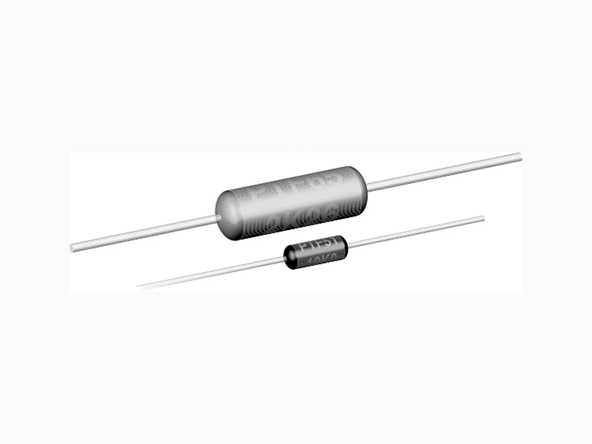
www.vishay.com Vishay Dale Revision: 15-Nov-12 1 Document Number: 31019 For technical questions, contact: ff2aresistors@vishay.com THIS DOCUMENT IS SUBJECT TO CHANGE WITHOUT NOTICE. THE PRODUCTS DESCRIBED HEREIN AND THIS DOCUMENT ARE SUBJECT TO SPECIFIC DISCLAIMERS, SET FORTH AT www.vishay.com/doc?91000 Metal Film Resistors, High Precision, High Stability
FEATURES
- Extremely low tempera ture coefficient of resistance
- Very low noise and voltage coefficient
- Very good high frequency characteristics
- Can replace wirewound bobbins
- Proprietary epoxy coating provides superior moisture protection
- For surface mount prod uct, see Vishay Dale’s PSF datasheet (www.vishay.com/doc?30162
- Material categorization: For definitions of compliance please see www.vishay.com/doc?99912 Note * Lead (Pb)-containing terminations are not RoHS-compliant. Exemptions may apply. Notes
- DSCC has created a drawing to support the need for a precision axial-leaded product. Vishay Dale is listed as a resource on th is drawing as follows: This drawing can be viewed at: www.landandmaritime.dla.mil/Programs/MilSpec/ListDwgs.aspx?DocTYPE=DSCCdwg (1) Continuous working voltage shall be or maximum working voltage, whichever is less. (2) Hot solder dipped leads. (3) For operation of the PTF resistors at higher power ratings, see the Load Life Shift Due to Power and Derating table. This tabl e gives a summary of the effects of using the PTF product at the more common combinations of power rating and case size, as well as quantifies the load life stability under those conditions. Notes
- For additional information on packaging, refer to the Through-Hole Resistor Packaging document (www.vishay.com/doc?31544 (4) Historical tolerance codes were BB for 0.01 % and BC for 0.02 %. STANDARD ELECTRICAL SPECIFICATIONS GLOBAL MODEL HISTORICAL MODEL POWER RATING (3) P85 °C W LIMITING ELEMENT VOLTAGE MAX. (1) V TEMPERATURE COEFFICIENT ± ppm/°C TOLERANCE ± % RESISTANCE RANGE DSCC DRAWING NUMBER VISHAY DALE MODEL POWER RATING P 85 °C W RESISTANCE RANGE TOLERANCE ± % TEMPERATURE COEFFICIENT ± ppm/°C MAXIMUM WORKING VOLTAGE (1) V 89088 PTF56..31, 90038 PTF65..16, TEMPERATURE COEFFICIENT CODES GLOBAL TC CODE HISTORICAL TC CODE TEMPERATURE COEFFICIENT Z T-16 5 ppm/°C Y T-13 10 ppm/°C X T-10 15 ppm/°C GLOBAL PART NUMBER INFORMATION P x R RESISTANCE TOLERANCE MODEL VALUE CODE PTF51 R = Ω K = kΩ M = MΩ 15R000 = 15 Ω 500K00= 500 kΩ 1M0000= 1.0 MΩ T = ± 0.01 % (4) Z = 5 ppm EK = Lead (Pb)-free, bulk EA = Lead (Pb)-free, T/R (full) EB = Lead (Pb)-free, T/R (1000 pieces) BF = Tin/lead, bulk RE = Tin/lead, T/R (full) R6 = Tin/lead, T/R (1000 pieces) PTF65 A = ± 0.05 % X = 15 ppm B = ± 0.1 % 0 = Special C = ± 0.25 % D = ± 0.5 % F = ± 1 % New Global Part Numbering: PTF5620K500BYRE (preferred part numbering format) PT F 5 6 2 0K5 0 0BY Historical Part Number example: PTF-5620K5BT-13R36 (will continue to be accepted) Blank = Standard (Dash number) (Up to 3 digits) From 1 to 999 PACKAGING as applicable PTF56 R E TEMP . COEFFICIENT SPECIALGLOBAL HISTORICAL MODEL PTF-56 RESISTANCE VALUE 20K5 TOLERANCE CODE B TEMP. COEFFICIENT T-13 PACKAGING R36
www.vishay.com Vishay Dale Revision: 15-Nov-12 2 Document Number: 31019 For technical questions, contact: ff2aresistors@vishay.com THIS DOCUMENT IS SUBJECT TO CHANGE WITHOUT NOTICE. THE PRODUCTS DESCRIBED HEREIN AND THIS DOCUMENT ARE SUBJECT TO SPECIFIC DISCLAIMERS, SET FORTH AT www.vishay.com/doc?91000 DIMENSIONS Note (1) Lead length for product in bulk pack. For product supplied in tape and reel, the actual lead length would be based on the body size, tape spacing and lead trim. TECHNICAL SPECIFICATIONS PARAMETER UNIT PTF51 PTF56 PTF65 Rated Dissipation at 85 °C W 0.05 0.125 0.25 Limiting Element Voltage V 200 300 500 Insulation Voltage (1 Min) V eff > 500 > 500 > 500 Thermal Resistance K/W < 1300 < 520 260 Terminal Strength, Axial N > 150 > 50 > 50 Insulation Resistance 10 11 1011 1011 Category Temperature Range °C - 55 to + 150 - 55 to + 150 - 55 to + 150 Failure Rate 10 -9/h < 1 < 1 < 1 Weight (Max.) g 0.11 0.35 0.75 L1 max. (38.10 ± 3.18) d GLOBAL MODEL DIMENSIONS in inches (millimeters) LD L 1 max. d PTF51 0.150 ± 0.020 (3.81 ± 0.51) 0.070 ± 0.010 (1.78 ± 0.25) 0.200 (5.08) 0.016 (0.41) PTF56 0.250 ± 0.031 (6.35 ± 0.79) 0.091 ± 0.009 (2.31 ± 0.23) 0.300 (7.62) 0.025 (0.64) PTF65 0.375 ± 0.062 (9.53 ± 1.57) 0.145 ± 0.016 (3.68 ± 0.41) 0.475 (12.07) 0.025 (0.64) PERFORMANCE TEST CONDITIONS OF TEST TEST RESULTS (TYPICAL TEST LOTS) Life (at Standard Power Ratings) MIL-PRF-55182 Paragraph 4.8.18 1000 h rated power at + 85 °C ± 0.04 % Thermal Shock Mil-STD-202, Method 107 Short Time Overload MIL-R-10509, Paragraph 4.7.6 ± 0.01 % Low Temperature Operation MIL-PRF-55182, Methods 4.8.10 ± 0.02 % Moisture MIL-PRF-55182, Paragraph 4.8.15 ± 0.08 % Resistance to Soldering Heat MIL-STD-202, Methods 210 ± 0.02 % Damp Heat IEC 60068-2-3 56 days at 40 °C and 92 % RH ± 0.08 % Dielectric Withstanding Voltage MIL-STD-202, Methods 301 and 105 ± 0.01 % MATERIAL SPECIFICATIONS Element Precision deposited nickel chrome alloy with controlled annealing Encapsulation Specially formulated epoxy compounds. Coated construction Core Fire-cleanded hi gh purity ceramic Termination Standard lead material is solder-coated copper. Solderable and weldable per MIL-STD-1276, Type C. MARKING Temperature coefficient: T10 = 15 ppm, T13 = 10 ppm, T16 = 5 ppm PTF51: (3 lines) PTF 56, PTF65: (4 lines) PTF51 Style and size PTF56 Style and size 37K4 Value 49K9 Value BC T13 Tolerance and TC BB T16 Tolerance and TC 1211 4-digit date code
www.vishay.com Vishay Dale Revision: 15-Nov-12 3 Document Number: 31019 For technical questions, contact: ff2aresistors@vishay.com THIS DOCUMENT IS SUBJECT TO CHANGE WITHOUT NOTICE. THE PRODUCTS DESCRIBED HEREIN AND THIS DOCUMENT ARE SUBJECT TO SPECIFIC DISCLAIMERS, SET FORTH AT www.vishay.com/doc?91000 LOAD LIFE SHIFT DUE TO POWER AND DERATING (AT 85 °C) The power rating for the PTF parts is tied to the derating temperature, the heat rise of the parts, and the R for the load life performance. When the tables/graphs below are used together they show that when the parts are run at higher power ratings, the parts will run hotter, which has the potential of causing the resistance of the parts to shift more over the life of the part. LOAD LIFE SHIFT VS. POWER RATING LOAD LIFE CONDITIONS OF TEST MAXIMUM R (TYPICAL TEST LOTS) MIL-PRF-55182 Paragraph 4.8.18 MODEL POWER RATING AT + 85 °C PTF51 1/20 W 1/10 W 1/8 W 1/4 W PTF56 1/8 W - 1/4 W 1/2 W PTF65 1/4 W - 1/2 W 3/4 W Example: When a PTF56 part is run at 1/8 W in a 70 °C ambient environment, the resistor will generate enough heat that the surface temperature of the part will reach about 17 °C over the ambient temperature, and over the life of the part this could cause the resistance value to shift up to ± 0.04 %. If the same resistor was instead run at 1/4 W in a 70 °C environment, the element will heat up to about 30 °C over ambient, and over the life of the part the resistance value could shift roughly ± 0.5 %. And if the resistor was run at its maximum power rating of 1/2 W in a 70 °C environment, it will heat up to about 61°C over ambient, and you could see the resistance value shift roughly ± 1 % over the life of the part. TEMPERATURE COEFFICIENT OF RESISTANCE Temperature coefficient (TC) of resistance is normally stated as the maximum amount of resistance change from the original + 25 °C value as the ambient temperature increases or decreases. This is most commonly expressed in parts per million per degree centigrade (ppm/°C). The resistance curve over the operating temperature range is usually a non-linear curve within predictable maximum limits. PTF resistors have a very unifom resistance temperature characteristic when measured over the operating range of - 20 °C to + 85 °C. The standard temperature coefficients available are X = ± 15 ppm/°C, Y = ± 10 ppm/°C and Z = ± 5 ppm/°C. Some applications of the PTF require operation beyond the specifications of - 20 °C to + 85 °C. The change in temperature coefficient of resistance is very small (less than ± 0.05 ppm/°C) over the expanded temperature range of - 55 °C to + 150 °C. Therefore, when operating outside the range - 20 °C to + 85 °C, the designer can plan for a worst case addition of ± 0.05 ppm/°C for each degree centigrade beyond either - 20 °C or + 85 °C as indicated in the graph. This applies to all three temperature coefficient codes. Example: Assume the operating characteristics demand a temperature range from - 55 °C to + 125 °C. This requires a ± 35 °C below - 20 °C and a ± 40 °C above + 85 °C. The extreme being ± 40 °C means that the worst case addition to the specified TC limit of ± 0.05 ppm/°C times ± 40 °C or ± 2 ppm/°C. Therefore, a Z which is characterized by a base TC limit of ± 5 ppm/°C over the temperature range of - 20 °C to + 85 °C will exhibit a maximum temperature coefficient of ± 7 ppm/°C over the expanded portion of the temperature range of - 55 °C to + 125 °C. AMBIENT TEMPERATURE IN °C DERATING RATED POWER IN % 100 120 - 55 - 25 0 25 50 75 100 125 150 175 200 100 120 APPLIED POWER IN W HEAT RISE (°C ABOVE AMBIENT) THERMAL RESISTANCE PTF65 PTF56PTF51 - 50 - 40 - 30 - 20 90 100 110 120 130 140 150 EXPANDED OPERATING RANGE - 55 °C TO - 20 °C EXPANDED OPERATING RANGE - 85 °C TO + 150 °C - 20 °C TO + 85 °C BASE TC LIMIT X, Y or Z ppm/°C EHT NI CT ESAB OT NOITIDDA EHT FO NOITROP DEDNAPXE EGNAR ERUTAREP MET
www.vishay.com Vishay Revision: 02-Oct-12 1 Document Number: 91000 Disclaimer ALL PRODUCT, PRODUCT SPECIFICATIONS AND DATA ARE SUBJECT TO CHANGE WITHOUT NOTICE TO IMPROVE RELIABILITY, FUNCTION OR DESIGN OR OTHERWISE. Vishay Intertechnology, Inc., its affiliates, agents, and employee s, and all persons acting on it s or their behalf (collectivel y, “Vishay”), disclaim any and all liability for any errors, inaccuracies or incompleteness contained in any datasheet or in any other disclosure relating to any product. Vishay makes no warranty, repres entation or guarantee regarding the suitabilit y of the products for any particular purpose or the continuing production of any product. To the maximum extent permitted by applicable law, Vishay disclaims (i) any and all liability arising out of the application or use of any product, (ii) any and all liability, including without limitation specia l, consequential or incidental damages, and (iii) any and all i mplied warranties, including warra nties of fitness for particular purpose, non-infringement and merchantability. Statements regarding the suitability of products for certain type s of applications are based on Vishay’s knowledge of typical requirements that are often placed on Vishay products in generic applications. Such statements are not binding statements about the suitability of products for a particular application. It is the customer’s responsib ility to validate that a particu lar product with the properties descri bed in the product specification is suitable fo r use in a particular application. Parameters provided in datasheets and/or specification s may vary in different applications an d performance may vary over time. All operating parameters, including typical pa rameters, must be validated for each customer application by the customer’s technical experts. Product specifications do not expand or otherwise modify Vish ay’s terms and condit ions of purchase, including but not limited to the warranty expressed therein. Except as expressly indicate d in writing, Vishay products are not designed for use in medical, life-saving, or life-sustaining applications or for any other application in which the failure of the Vi shay product could result in personal injury or death. Customers using or selling Vishay products not expressly indicated for use in such applications do so at their own risk. Please contact authorized Vishay personnel to obtain written terms and conditions regarding products designed for such applications. No license, express or implied, by estoppel or otherwise, to any intellectual prope rty rights is granted by this document or by any conduct of Vishay. Product names and markings noted herein may be trademarks of their respective owners. Material Category Policy Vishay Intertechnology, Inc. hereby certi fies that all its products that are id entified as RoHS-Compliant fulfill the definitions and restrictions defined under Directive 2011/65/EU of The Euro pean Parliament and of the Council of June 8, 2011 on the restriction of the use of certain hazardous substances in electrical and electronic equipment (EEE) - recast, unless otherwise specified as non-compliant. Please note that some Vishay documentation may still make reference to RoHS Directive 2002/95/EC. We confirm that all the products identified as being compliant to Directive 2002/95/EC conform to Directive 2011/65/EU. Vishay Intertechnology, Inc. hereby certifies that all its products that are identified as Halogen-Free follow Halogen-Free requirements as per JEDEC JS709A standards. Please note that some Vishay documentation may still make reference to the IEC 61249-2-21 definition. We co nfirm that all the products identified as being compliant to IEC 61249-2-21 conform to JEDEC JS709A standards.