
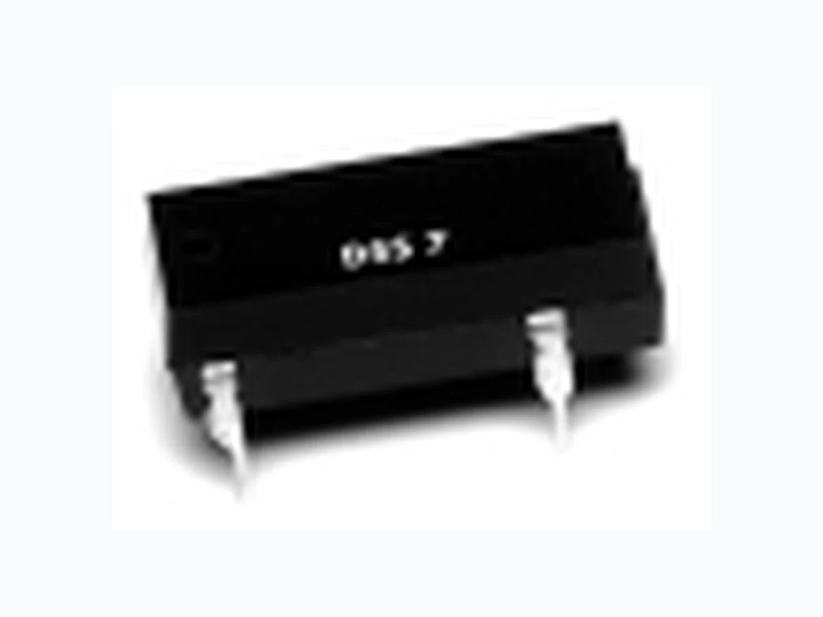
MSS71A05 ETC1
Document overview
- Manufacturer or author: Provided By www.digicamel.com(FREE DATASHEET DOWNLOAD SITE)
- PDF pages: 9
Technical content
DESCRIPTION
I MSS7 I PRMA I DSS7 I PRME I MVS2 I MVS7 RATINGS (@ 25˚ C)
APPLICATIONS
FEATURES
SRC Device’s epoxy molded DIP 14 Series offers a variety of contacts and schematics to meet the needs of a wide range of applications. It features the MVS2/MVS7 models designed for high reliability. The MSS2/7 DIPs are 1-Form-A relays equipped with the MYAD all-position mounting switch. With switching up to 50 Watts and a 4000V isolation option, the DIP 14 Series is a relay package that allows for automatic insertion directly on PCBs as well as insertion into standard 14 Pin DIP sockets. I All position mercury contacts on some models I Stable contact resistance over life I
4000 Vac input-output isolation
I Bounce free operation I High insulation resistance I Switching speed of 300Hz I Long life > 1 billion operations I Epoxy molded for automatic board processing I FCC68 compatible (MSS2 & MSS7) I Automatic test equipment I Process control I Industrial I Telecom I Datacom I High-end security systems I Signaling I Metering I UL approval (DSS7 & PRMA) I EN 60950 certified (MVS7, DSS7 & MSS7) I CSA approval (PRMA) Parameter Min Typ Max Unit Switching Voltage PRMA/PRME/DSS7 200 Volts PRMA Form C 100 Volts MSS2/MSS7 500 Volts MVS2/MVS7 1000 Volts Switching Current PRMA/PRME/DSS7 0.5 Amps PRMA Form C 0.25 Amps MSS2/MSS7/MVS2/MVS7 2 Amps Carry Current PRMA/PRME/DSS7 2 Amps PRMA Form C 0.4 Amps MSS2/MSS7 3 Amps MVS2/MVS7 3 Amps Switching Frequency PRMA/PRME/DSS7 500 Hz PRMA Form C 50 Hz MSS2/MSS7/MVS2/MVS7 200 Hz Contact Resistance PRMA/PRME/DSS7 150 m Ω PRMA Form C 200 m Ω MSS2/MSS7/MVS2/MVS7 100 m Ω (See detailed specifications for more information.) SRC DEVICES SRC DEVICES www.srcdevices.com
I MSS7 I PRMA I DSS7 I PRME I MVS2 I MVS7 All parameters are at 25°C unless otherwise stated. Operate voltage, release voltage, and coil resistance will change approximately 0.4%/°C as ambient temperature varies. MSS2 Molded 8 Pin All position Wetted contacts MSS7 Molded 4 Pin All position Wetted contacts PARAMETER CONDITIONS SYMBOL MIN TYP MAX MIN TYP MAX UNITS Contact Ratings Switching Voltage Max DC/PeakAC Resistive V L - - 500 - - 500 Volts Switching Current Max DC/PeakAC Resistive I L - - 2 - - 2 Amps Carry Current Max DC/PeakAC Resistive I C - - 3 - - 3 Amps Contact Rating Max DC/PeakAC Resistive - - 50 - - 50 Watts Life Expectancy Signal Level 1.0 V 10mA - 200 - - 200 - x10 Ops Related Loads (1) Static Contact Resistance 50mV, 10mA CR - 40 100 - 65 100 m Ω Dynamic Contact Resistance .5V, 50mA at 100Hz, 1.5 msec DCR - N/A - - N/A - m Ω Contact Material - Hg - - Hg - Hg Content - 16 - - 16 - mgrams Relay Specifications Insulation Resistance Between all isolated pins IR 10 -1 0 - Ω at 100V, 25°C, 40% RH Capacitance Across Open Contacts - 1.5 2 - 1.2 2 pF Open Contact to Coil 3 4 - 3 4 pF Dielectric Strength Between Contacts 1400 - - 2000 - - VDC/Peak AC Contacts to Coil I/O 1400 - - 5600 - - VDC/Peak AC Operate Time, At Nominal Coil Voltage T OP - 1.2 1.75 - 1.2 1.75 ms including bounce 10Hz Square Wave Release Time Zener-Diode Suppression T REL - 1 1.50 - 1 1.50 ms Environmental Ratings Storage Temperature T A Operating Temperature T O Soldering Temperature Applied to pins, 5 sec. max. - 260 - - 260 °C Vibration Resistance 10Hz - 500Hz G - - 10 - - 10 Gs (Survival) Shock Resistance 11±1ms, Sine Wave S - - 30 - - 30 Gs (Survival) Weight - 2.3 - - 2.3 - grams (1) Refer to life graphs SRC DEVICES USA 1-866-SRC-8668 Europe 32-89-328850 Far East 886-2-2698-8422 www. srcdevices.com
MSS2 I MSS7 I PRMA I DSS7 I PRME I MVS2 I MVS7 All parameters are at 25° C unless otherwise stated. Operate voltage, release voltage, and coil resistance will change approximately 0.4%/° C as ambient temperature varies. PRMA Molded 8 Pin Form-C Dry Reed PRMA Molded 8 Pin Form-A&B Dry Reed PARAMETER CONDITIONS SYMBOL MIN TYP MAX MIN TYP MAX UNITS Contact Ratings Switching Voltage Max DC/PeakAC Resistive V L - 100 - - 200 Volts Switching Current Max DC/PeakAC Resistive I L - 0.25 - - 0.5 Amps Carry Current Max DC/PeakAC Resistive I C - 0.4 - - 2 Amps Contact Rating Max DC/PeakAC Resistive - 3 - - 10 Watts Life Expectancy Signal Level 1.0V 10mA - 20 - 300 500 - x10 6 Ops Related Loads(1) Static Contact Resistance 50mV, 10mA CR - 200 - - 150 m Ω Dynamic Contact Resistance .5V, 50mA at 100Hz, 1.5 msec DCR - N/A - - N/A - m Ω Contact Material - Rh - - Ru - Relay Specifications Insulation Resistance Between all isolated pins IR 10 9 1010 -1 0 10 1012 - Ω at 100V, 25° C, 40% RH Capacitance Across Open Contacts - 2.5 3 - 0.7 1 pF Open Contact to Coil 3 3 - 1.5 2 pF Dielectric Strength Between Contacts 250 - - 250 - - VDC/Peak AC Contacts to Coil I/O 1400 - - 1400 - - VDC/Peak AC Operate Time, At Nominal Coil Voltage T OP - 1.5 2 - .25 0.5 ms including bounce 10Hz Square Wave Release Time Zener-Diode Suppression T REL - 1.5 3 - .25 0.5 ms Environmental Ratings Storage Temperature T A -40 - +105 -40 - +105 ° C Operating Temperature T O -40 - +80 -40 - +80 ° C Soldering Temperature Applied to pins, 5 sec. max. - 260 - - - 260 ° C Vibration Resistance(2) 10 Hz - 500 Hz for PRMA Form A&B G - - 10 - - 20 Gs (Survival) 5Hz - 500Hz for PRMA Form C Shock Resistance 11±1ms, 1/2 Sine Wave S - - 50 - - 100 Gs (Survival) Weight - 1.5 - - 1.5 - grams (1) Refer to life graphs (2) Use caution not to exceed vibration resistance limits while ultrasonically cleaning relays with DYAD switches. Contact SRC Devices Engineering for more details/recommendations. SRC DEVICESSRC DEVICES 3www. srcdevices.com USA 1-866-SR C -8668 Europe 32-89-328850 Far East 886-2-2698-8422
All parameters are at 25° C unless otherwise stated. Operate voltage, release voltage, and coil resistance will change approximately 0.4%/° C as ambient temperature varies. DSS7 Molded 4 Pin Dry Reed PRME Molded 8 Pin Low profile Dry Reed PARAMETER CONDITIONS SYMBOL MIN TYP MAX MIN TYP MAX UNITS Contact Ratings Switching Voltage Max DC/PeakAC Resistive V L - - 200 - 200 Volts Switching Current Max DC/PeakAC Resistive I L - - 0.5 - 0.5 Amps Carry Current Max DC/PeakAC Resistive I C - - 2 - 2 Amps Contact Rating Max DC/PeakAC Resistive - - 10 - 10 Watts Life Expectancy Signal Level 1.0 V 10mA 300 500 - 300 500 - x10 6 Ops Related Loads(1) Static Contact Resistance 50mV, 10mA CR - - 150 - 150 m Ω Dynamic Contact Resistance .5V, 50mA at 100Hz, 1.5 msec DCR - N/A - - N/A - m Ω Contact Material - Ru - - Ru - Relay Specifications Insulation Resistance Between all isolated pins IR 10 10 1012 -1 0 10 1012 - Ω at 100V, 25° C, 40% RH Capacitance Across Open Contacts - 0.7 1 - 0.8 1 pF Open Contact to Coil 1.5 2 1.5 2 pF Dielectric Strength Between Contacts 250 - - 250 - - VDC/Peak AC Contacts to Coil I/O 5600 1000 VDC/Peak AC Operate Time, At Nominal Coil Voltage T OP - 0.25 0.5 - 0.25 1 ms including bounce 10Hz Square Wave Release Time Zener-Diode Suppression T REL - 0.25 0.5 - 0.25 0.5 ms Environmental Ratings Storage Temperature T A -40 - +105 -40 - +105 ° C Operating Temperature T O -40 - +80 -40 - +80 ° C Soldering Temperature Applied to pins, 5 sec. max. - - 260 - - 260 ° C Vibration Resistance(2) 5Hz - 500Hz G - - 20 - - 20 Gs (Survival) Shock Resistance 11±1ms, 1/2 Sine Wave S - - 100 - - 100 Gs (Survival) Weight - 1.5 - - 1.5 - grams (1) Refer to life graphs (2) Use caution not to exceed vibration resistance limits while ultrasonically cleaning relays with DYAD switches. Contact SRC Devices Engineering for more details/recommendations. MSS2 I MSS7 I PRMA I DSS7 I PRME I MVS2 I MVS7 SRC DEVICES 4www. srcdevices.com USA 1-866-SR C -8668 Europe 32-89-328850 Far East 886-2-2698-8422
MSS2 I MSS7 I PRMA I DSS7 I PRME I MVS2 I MVS7 All parameters are at 25° C unless otherwise stated. Operate voltage, release voltage, and coil resistance will change approximately 0.4%/° C as ambient temperature varies. MVS7
4 Pin DIP
Wetted Contacts(3) MVS2
8 Pin DIP
Wetted Contacts(3) PARAMETER CONDITIONS SYMBOL MIN TYP MAX MIN TYP MAX UNITS Contact Ratings Switching Voltage Max DC/PeakAC Resistive V L - - 1000 (1) - - 1000 (1) Volts Switching Current Max DC/PeakAC Resistive I L - - 2 - - 2 Amps Carry Current Max DC/PeakAC Resistive I C - - 3 - - 3 Amps Contact Rating Max DC/PeakAC Resistive - - 50 - - 50 Watts Life Expectancy Signal Level 1.0 V 10mA 1000 - - 1000 - - x10 6 Ops 50V, 1A - 2 - - 2 - x10 6 Ops 500V, 100mA - 50 - - 50 - x10 6 Ops Related Loads(2) Static Contact Resistance 50mV, 10mA CR - - 100 - - 100 m Ω Contact Material - Hg - - Hg - Hg Content - 40 - - 40 - mgrams Relay Specifications Insulation Resistance Between all isolated pins IR 10 10 1012 -1 0 10 1012 - Ω at 100V, 25° C, 40% RH Capacitance Across Open Contacts - 0.7 - - 0.7 - pF Upper Contact to Coil - 1.2 - - 1.5 - pF Closed Contact to Coil - 3.2 - - 2.5 - pF Dielectric Strength Open Contacts 1400 - - 2000 - - VDC/Peak AC Contacts to Coil I/O 1400 - - 5600 - - VDC/Peak AC Operate Time At Nominal Coil Voltage T OP - 1.5 2.5 - 1.5 2.5 ms 10Hz Square Wave Release Time Zener-Diode Suppression T REL - 1 2.5 - 1 2.5 ms Environmental Ratings Storage Temperature T A -40 - +105 -40 - +105 ° C Operating Temperature T O +260 +260 ° C Soldering Temperature Applied to pins, 5 sec. max. -38 - +85 -38 - +85 ° C Vibration Resistance(2) 10Hz - 500Hz G - - 10 - - 10 Gs (Survival) Shock Resistance 11±1ms, 1/2 Sine Wave S - - 30 - - 30 Gs (Survival) Weight - 2.1 - - 2.1 - grams (1) Current limited up to 5mA, minimum 20 million operations; for further information, consult factory (2) Refer to life graphs (3) Relay contains mercury welted contacts and must be mounted vertically. Pin 1 is up. SRC DEVICESSRC DEVICES 5www. srcdevices.com USA 1-866-SR C -8668 Europe 32-89-328850 Far East 886-2-2698-8422
MSS2 I MSS7 I PRMA I DSS7 I PRME I MVS2 I MVS7 COIL SPECIFICATIONS Contact Form Coil Voltage Coil Resistance Operate Voltage Release Voltage Nominal Input Power Units Volts Ω Volts Volt mW Conditions +/- 10% (25°C) Must operate by (25°C)Must release by (25°C) Part # Min Typ Max Min Typ Max Min Typ Max Min Typ Max Min Typ Max MSS2 1A05 1-Form-A 5 11 126 140 154 3.75 0.5 179 MSS2 1A12 1-Form-A 12 21 450 500 550 9 1 288 MSS2 1A24 1-Form-A 24 44 1935 2150 2365 18 2 268 MSS7 1A05 1-Form-A 5 11 126 140 154 3.75 0.5 179 MSS7 1A12 1-Form-A 12 21 450 500 550 9 1 288 MSS7 1A24 1-Form-A 24 43 1935 2150 2365 18 2 268 PRMA 1A05 1-Form-A 5 21 450 500 550 3.75 0.8 50 PRMA 1A12 1-Form-A 12 30 900 1000 1100 9 1 144 PRMA 1A24 1-Form-A 24 44 1935 2150 2365 18 2 268 PRMA 1B05 1-Form-B 5 6 450 500 550 3.75 0.8 50 PRMA 1B12 1-Form-B 12 14.5 900 1000 1100 9 1 144 PRMA 1B24 1-Form-B 24 29 1935 2150 2365 18 2 268 PRMA 1C05 1-Form-C 5 12 180 200 220 3.75 0.8 125 PRMA 1C12 1-Form-C 12 18 450 500 550 9 1 288 PRMA 1C24 1-Form-C 24 32 1935 2150 2365 18 2 268 PRMA 2A05 2-Form-A 5 11 126 140 154 3.75 0.8 179 PRMA 2A12 2-Form-A 12 21 450 500 550 9 1 288 PRMA 2A24 2-Form-A 24 44 1935 2150 2365 18 2 268 PRMA 10037 1-Form-A 5 15 342 380 418 3.75 0.8 66 PRMA 10038 1-Form-A 12 19 477 530 583 9 1 272 PRMA 10039 1-Form-A 24 32 1800 2000 2200 18 2 288 DSS7 1A05 1-Form-A 5 21 450 500 550 3.75 0.8 50 DSS7 1A12 1-Form-A 12 30 900 1000 1100 9 1 144 DSS7 1A24 1-Form-A 24 44 1935 2150 2365 18 2 268 PRME 25005 1-Form-A 5 19 450 500 550 3.8 0.8 50 PRME 15005 1-Form-A 5 15 342 380 418 3.5 1 66 PRME 15002 1-Form-A 12 19 477 530 583 8 1 272 PRME 15003 1-Form-A 24 32 1800 2000 2200 16 2 288 MVS2 1A05(A,B) 1-Form-A 5 7 94.5 105 116 3.75 0.5 238 MVS2 1A12(A,B) 1-Form-A 12 15 450 500 550 9 1 288 MVS2 1A24(A,B) 1-Form-A 24 30 1935 2150 2365 18 2 268 MVS7 1A05(S) 1-Form-A 5 7 94.5 105 116 3.75 0.5 238 MVS7 1A12(S) 1-Form-A 12 15 450 500 550 9 1 288 MVS7 1A24(S) 1-Form-A 24 30 1935 2150 2365 18 2 268 SRC DEVICES 6www. srcdevices.com USA 1-866-SR C -8668 Europe 32-89-328850 Far East 886-2-2698-8422
MSS2 I MSS7 I PRMA I DSS7 I PRME I MVS2 I MVS7 PERFORMANCE GRAPHS PRMA Life/Contact Load Characteristics (Confidence Level 99%) Contact Load (mA) Voltage (Vdc) 100 200 300 400 Life: >10x106 Operations PRMA Allowable Operating Range Operating Frequency Duty Cycle (%) 100 200 400 600 1000 800 PRMA Operate Time vs Nominal Voltage Multiple of Nominal Voltage Operate Time (µs) 500 400 300 200 100 0.5 1 1.5 2.5 2 PRMA Contact Noise Envelope (Bandwidth 10KHz) Time After Coil Energization (ms) Contact Noise (µV) -20 -40 -60 123 5 6 4 547 10K 1A7A Tektronix MSS2/MSS7 Operate Time vs Nominal Voltage (with Diode Suppression) Multiple of Nominal Voltage A = +3δ B = -3δ Operate Time (ms) 0.9 0.6 0.3 1.2 2.4 2.1 1.8 3.3 3.0 2.7 1.5 A B MSS2/MSS7 Timing (with Diode Suppression) Multiple of Nominal Voltage A = +3δ B = -3δ Release Time (ms) 0.9 0.6 0.3 1.2 2.4 2.1 1.8 3.3 3.0 2.7 1.5 A B MSS2/MSS7 Magnetic Interference X = Distance (in.) between centers of adjacent relays. (For distance between relay bodies, subtract .400) % Change -10 -15 -20 0.2 0.4 0.6 0.8 MVS7/MSS7 Relay Internal Temperature Rise vs. Power Power (W) Temperature Rise (¡C) (Typ.) 0.2 0.4 0.6 0.8 SRC DEVICESSRC DEVICES 7www. srcdevices.com USA 1-866-SR C -8668 Europe 32-89-328850 Far East 886-2-2698-8422
MSS2 I MSS7 I PRMA I DSS7 I PRME I MVS2 I MVS7 MECHANICAL DIMENSIONS 19.60 MAX. (0.772) PRMA 6.90 MAX. (0.272) 6.70 MAX. (0.264) 7.33 MAX. (0.289) 15.24 (0.600) 10.16 (0.400) 0.49 (0.019) 3.20 – 0.25 (0.125 – 0.009) 7.62 (0.300) 8.90 MAX. (0.350) 0.28 (0.011) Top View 19.60 (0.772) PRME 5.00 MAX. (0.197) 5.30 – 0.10 (0.208 – 0.003) 10.16 (0.400) 15.24 (0.600) 0.46 (0.018) 3.20 – 0.25 (0.125 – 0.009) 7.62 (0.300) 8.90 MAX. (0.350) 0.28 (0.011) 6.40 (0.252) Top View 19.60 MAX. (0.772) DSS7 6.90 MAX. (0.272) 6.70 MAX. (0.264) 7.33 MAX. (0.289) 15.24 (0.600) 10.16 (0.400) 0.49 (0.019) 3.20 – .25 (0.125 – 0.009) 7.62 (0.300) 8.90 MAX. (0.350) 0.28 (0.011) Top View PRMA 1A Top View Options: Diode - pin #2 is positive Electrostatic shield - pin 9 PRMA 1B Top View Options: Diode - pin #2 is positive Electrostatic shield - pin 9 PRMA 1C Top View Options: Diode - pin #2 is positive Electrostatic shield - pin 9 PRMA 2A Top View Options: Diode - pin #2 is positive Electrostatic shield - pin 9 MVS2/MSS2 Top View * MVS2 only must be mounted vertically with pin #1 UP. UP PRMA 10037/10038/10039 Top View Options: Diode - pin #2 is positive Electrostatic shield - pin 9 PRME 11 4 Top View Options: Diode - pin #13 is positive Electrostatic shield - pin 9 DSS7 Top View MSV must be mounted verti- cally. Pin #1 is up. DIMENSIONS mm (inches) SRC DEVICES 8www. srcdevices.com USA 1-866-SR C -8668 Europe 32-89-328850 Far East 886-2-2698-8422
MSS2 I MSS7 I PRMA I DSS7 I PRME I MVS2 I MVS7
ORDERING INFORMATION
A complete part number is represented by the digits below. For example, the PRMA1A05 is a model 2 PRMA relay with a 1-Form A contact form, a nominal voltage of 5V and no extra options. XXXX XX XX X Series PRMA DSS7 Contact Form 1A = 1-Form-A 15 = 1-Form-A (PRME) 2A = 2-Form-A 1B = 1-Form-B 1C = 1-Form-C Options A = ES option B = Diode option C = Shield & diode option S = Modified pinout (Coil at 2 & 6, contact at 8 & 14, DSS7 only) Nominal Coil Voltage 05 = 5V 12 = 12V 24 = 24V full part numbers. SRC DEVICESSRC DEVICES 9www. srcdevices.com USA 1-866-SR C -8668 Europe 32-89-328850 Far East 886-2-2698-8422