
PR3-O UNITEDAUTOMATION
Document overview
- Manufacturer or author: Provided By www.digicamel.com(free datasheet download site)
- PDF pages: 2
Technical content
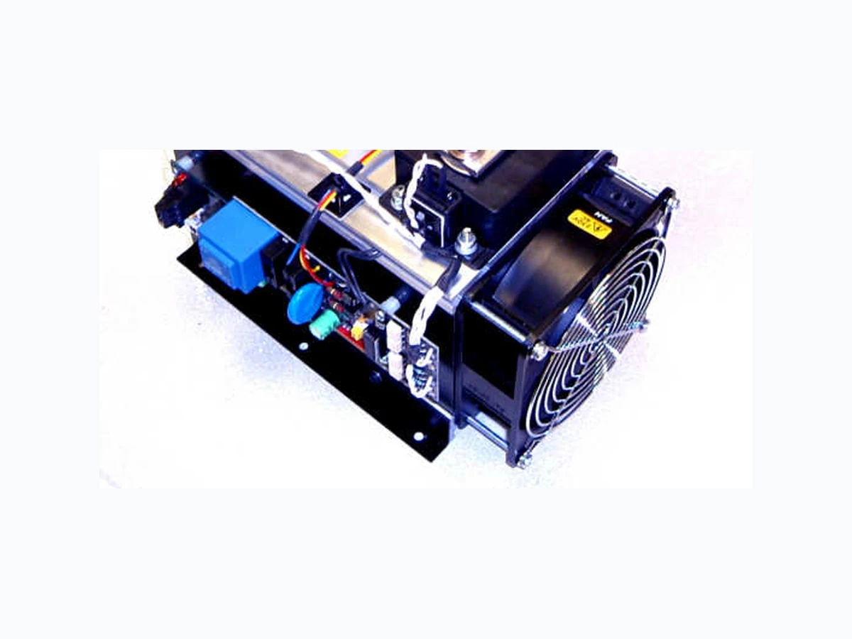
Burst fire control options (SW2) There are two methods which can be selected to suit specific applications. With the SW2 DIL switch in the “ON” position it gives fast burst control which is the ‘inhibited flicker’ mode. With the SW2 DIL switch in the “OFF” position it gives slow burst control, which is basic burst firing mode. Control input options (SW3 & SW”I/V”) These are connected via the terminals 5V o/p and “+” and “-” signal. Ensure correct polarity, as shown in CONNECTIONS section. [SW3] For input voltage signals of 0-5V or 0-10V dc, use the “+” and “–” SIGNAL terminals . [SW3] For manual control using a 5k Ω , 1W potentiometer, use all 3 terminals 5V-O/P , and “+” and “–” SIGNAL terminals. [SW “I/V”] For input current signal of 4-20mA, set DIL switch SW-I/V to “ON”, fit a 270 Ω , 0.25W resistor across the “+” and “-” SIGNAL terminals and set SW3 to 0-5V. Notes: a) For 4-20mA dc signal, a 270 Ω resistor is supplied. Factory-set ‘default’ setting is 0- 10V. b) Refer to L71036 CONNECTIONS Label fixed to unit. c) See also SPECIFICATIONS section. FUNCTIONS Alarm relay functions (3-way terminal – V/free alarm “NO_NC_C”) The alarm circuit has ‘voltage free’ relay contacts and are rated up to 2A @ 125V ac (RMS) load. Connection is via the PCB terminal. For alarm relay status options see SPECIFICATIONS. Note: The internal supply to the relay is obtained from the transformer via two 20mm 1A fuses. These are connected to the Black (L2) and Grey (L3) phases and therefore the relay and LED can only energise when there is an over-temperature condition, a sensor fault, or a phase loss on L1 phase. See Remote Supply option section. Over temperature protection When a heatsink temperature of above 90ºC is detected by the sensor, the alarms relay changes state and the status LED indicator flashes continuous rapid pulsing. The power to the load will be disconnected and will not return until the temperature drops to 85ºC. The 54kW unit is also fitted with a cooling fan that switches ON when the heatsink reaches approximately 55ºC. Temperature sensor loss The Status LED indicator changes to continuous equal ON/OFF pulsing if the sensor fails. PR3-O SERIES X10595 150kW and 225kW HVAC RANGE 3-PHASE BURST FIRE POWER REGULATOR INSTALLATION INSTRUCTIONS Phase loss with auxiliary supply When any one of the three phase inputs are missing, the relay changes state and the LED flashes with ON/OFF bursts of 1.5 seconds. This is only functional with a remote supply (see below). Fault condition The default setting of DIL switch (SW1) is in the ON position, the alarm relay will be energised under a fault condition. Changing SW1 to the off position will energise the alarm relay continuously until a fault condition occurs. Remote supply The unit will be factory set for an internal supply (SW4 in the “INT” position). If there is a requirement for the alarm relay and LED to energise when a phase fault condition occurs, then there is provision for an external 24V ac or dc supply (SW4 in the “EXT” position). NOTE – If the remote supply is utilised, the main (L1, L2 and L3) supply must come on before this supply is switched on. RoHS Compliant W D INTRODUCTION The PR3 range of thyristor stacks provides full seamless control of three phase resistive loads, using two thirds control technique. Signal control is by a dc signal – see CONTROL OPTIONS GUIDE section. These burst firing control stacks use fast pulse zero volts switching technology, to minimise flicker and eliminate RFI problems. They also incorporate an automatic resetting temperature trip, integral semiconductor fuses and heatsink. The two builds in this series are the 150kW and 225kW model. Both have easy access to signal and power terminals for simple installation. H
APPLICATIONS
Suitable for 3-wire, 3-phase floating-star or closed-delta configured resistive loads. This includes the Heating, Ventilating and Air Conditioning (HVAC) market for air curtain applications, but also for furnaces, ovens, dryers and hot plates. CONNECTIONS
This robust stack assembly has an operational temperature of 65° C when naturally cooled and has a built in 90° C over temperature trip on the heatsink as a safety feature. The unit should be mounted vertically, with heatsink fins top to bottom, and with sufficient surrounding air space to maximise natural convection cooling. If the unit is mounted in an enclosure or cabinet, adequate ventilation and/or forced air-cooling should be fitted. This PR3-O- range have a forced air cooling fan fitted, which is designed to be permanently “on” when in use. Load considerations The PR3 series of power controllers are designed for 3-wire, 3-phase floating-star or closed delta configured resistive loads. The PR3 series are 2-leg thyristor controllers and therefore unsuitable for 4-wire, 3-phase with star point to neutral configured loads. For further information on configured loads, see the ‘Application circuits’ section of our supporting datasheet – APC (ref. X10322). Unusual heating loads such as Molybdenum, Platinum or Tungsten have a typical 10:1 hot to cold resistance ratio and therefore, when cold, draw larger currents than normal. Connections This unit has Power terminals and simple clamp type terminal connectors for all auxiliary wiring requirements (see SPECIFICATIONS below). NOTE: It is factory set for an internal power supply. For alternative ‘voltage free’ alarm supply details see Functions section. Please contact our Technical support for further details. Fusing & over temperature It is recommended that fast acting semiconductor type fuses (as supplied) be used for protection. See SRA Data sheet X10255 for further information. It is recommended that a load break switch and a contact breaker is installed in the load supply. The supply to the contactor coil should be interrupted by an over-temperature thermostat located in the heater battery and also upon detection of airflow loss. CE Marking This family carries a “CE” marking. These burst fire controllers do not normally require a remote filter. For more information contact our sales desk. A Declaration of Conformity is available on request. SPECIFICATIONS Power/(current ratings): 150kW (209A); 225kW (313A) @ a typical supply of 415V RMS Input voltage: 400V RMS +/- 10% Frequency: 50/60Hz Control input options: Signal (using SW3): 0 to 10V dc (set as standard) / 0 to 5V; OR Manual: using 5K Potentiometer. For 4-20mA signal: set SW -I/V to “ON”, fit 270R (0.25W) across SIG.+/- and set SW3 to 0-5V. Burst fire control options: Slow Burst: 1 second proportional time base Fast Burst: variable and un-proportional time base. Alarm relay functions: The voltage free alarm circuit is rated for 125V ac @ 2A. Alarm relay status options: SW1 = “OFF” - Relay is continuously energised (normally closed); trips in fault condition. SW1 = “ON” - Relay is de-energised (normally open); closes in fault condition. Status indicator: (Tracking control signal) status LED indicator changes intensity. Cooling fan: 120mm² fan, 230V AC supply fitted as standard – other options available (i.e. 110V,& 24V ac). Over Temperature: Trip in temperature @ 90ºC, +/- 1ºC ( Status LED indicator ‘ flashes ’ with ON/OFF rapid pulsing). Trip out temperature @ 85ºC, +/- 1ºC. Phase loss detection: Status LED indicator ‘ flashes ’ ON/OFF continuously in slow 1.5 second intervals. Sensor loss detection: Status LED indicator ‘ flashes ’ ON/OFF continuously in equal intervals. Cable terminations: Phase power: M8 setscrew Earth: M6 stud – both c/w nut and washer. Remote supply Auxiliary alarm (relay): 2.5mm² rising clamp terminal block. Control signal: 2.5mm² rising clamp terminal block. Terminal torque settings: 12Nm to 15Nm for power and earth terminals only. Fusing 105kW: 250A High-Speed Semiconductor type fuse - 250MT or equivalent. 225kW: 355A High-Speed Semiconductor type fuse – 355MT or equivalent. Working temperature: 65 °C (maximum operational) Dimensions: (150kW) - 260mm (D) x 245mm (W) x 215mm (H) – view ed, as photo. (225kW) - 260mm (D) x 245mm (W) x 215mm (H) - viewed, as photo. Fixing centres: 4 x 5mmø holes on centres 141mm (W) x 170mm (L) OR (alternatively):- 2 x 5mmø centre holes on centres 141mm (W) x 100mm (L) referenced from end without fan. Weight: (all models) 6.5kg. Note: SAFETY WARNING – Isolate supply before removing cover; Metal parts, in particular the heatsink, may get very hot when the unit is fully operational; DO NOT COVER enclosure ventilation slots. It is essential that a load break switch and a contact breaker is installed in the load supply. The supply to the contactor coil should be interrupted by an over-temperature thermostat located in the heater battery and also upon detection of airflow loss. RECOMMENDATIONS Additional supporting documents, which may be appropriate for your application, are available on request. These include X10255: SRA – Safety Advise; X10213: ITA – Interaction (Causes & remedies for Burst fire & Phase Angle control), P01.1 – UAL Conditions of Sale. NOTE: It is recommended that installation and maintenance of this equipment should be done with reference to the current edition of the I.E.T. (formally I.E.E.) regulations (BS7671) by suitably qualified/trained personnel. The regulations contain important requirements regarding installation and safety of electrical equipment. Specific installers should refer to local and national regulations. © These products are protected by unregistered design with United Automation Limited, Southport, UK UNITED AUTOMATION LIMITED Southport Business Park Tel: 0044 (0) 1704 – 516 500 Wight Moss Way Fax: 0044 (0) 1704 – 516501 Southport, PR8 4HQ enquiries@united-automation.co m ENGLAND www.united-automation.com Page No. 2 of 2 Issue 7 Date 01/03/1 6 ORDER DETAILS When ordering directly, please use the following stock codes:- Manufacturer stock code Product Description Rating A447442-HV PR3-O-150kW (230V Fan) 3-phase, 150kW, 209A@415V, 2 /3rds control A447452-HV PR3-O-225kW (230V Fan) 3-phase, 225kW, 313A@415V, 2 /3rds control T30201 Auxiliary transformer for Failsafe Alarm 0/2 40/415 10-0-10V 2VA A403011 5k Ω, 1W Potentiometer with 0.5m long leads for manual control option -- Available on request Spare HS fuses: 250MT (250A) o r 355MT (355A), SCR-type --