
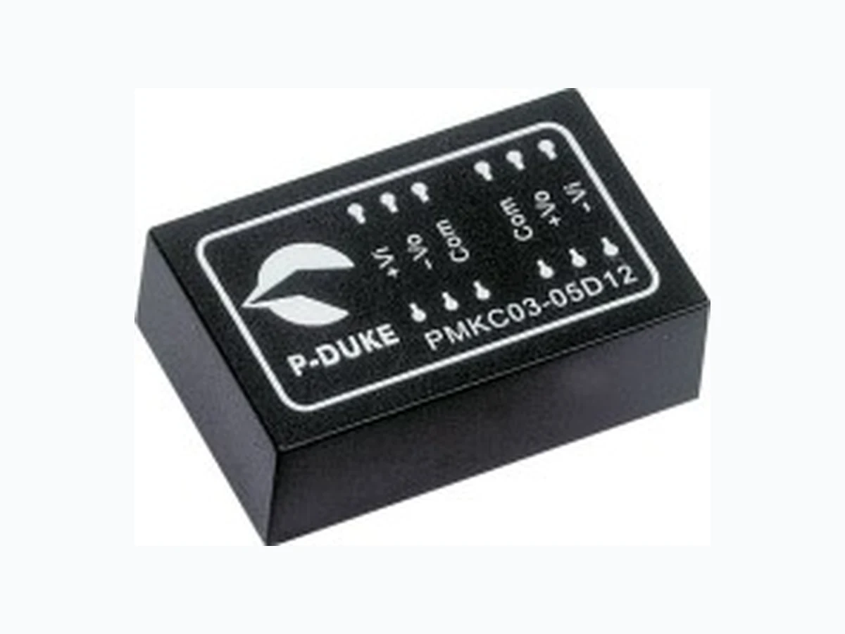
PMKC03 ETC1
Document overview
- Manufacturer or author: Provided By www.digicamel.com(FREE DATASHEET DOWNLOAD SITE)
- PDF pages: 3
Technical content
3 Watts max
Voltage accuracy Full load and nominal Vin ± 1% Minimum load (Note 1) 10% of FL Line regulation LL to HL at Full Load DS ± 0.2% ± 0.5% Load regulation 25% to 100% FL Single Dual DS ± 0.2% ± 2% ± 0.5% Cross regulation (Dual) Asymmetrical load 25% / 100% FL ± 5% Ripple and noise 20MHz bandwidth 3.3V/5V others 75mVp-p 1%/p-p of Vout max Temperature coefficient ±0.02% / ºC, max Transient response recovery time 25% load step change 500uS Over load protection % of FL at nominal input 180% typ Short circuit protection Continuous, automatics recovery INPUT SPECIFICATIONS Input voltage range 5V nominal input 12V nominal input 24V nominal input 48V nominal input 4.5 – 6VDC 9 – 18VDC 18 – 36VDC 36 – 75VDC Input filter Pi type Input surge voltage 100mS max 5V input 12V input 24V input 48V input 15VDC 36VDC 50VDC 100VDC Input reflected ripple (Note2) Nominal Vin and full load 120mAp-p Start up time Nominal Vin and constant resistive load Power up 30mS typ GENERAL SPECIFICATIONS Efficiency See table Isolation voltage Input to Output DS Type, Output to Output 1600VDC, min 500VDC, min Isolation resistance 9ohms, min Isolation capacitance 300pF, max Switching frequency 100KHz, min Approvals and standard IEC60950-1, UL1950-1, EN60950-1 Case material Non-conductive black plastic Base material Non-conductive black plastic Potting material Epoxy (UL94-V0) Dimensions 1.25 X 0.80 X 0.40 Inch (31.8 X 20.3 X 10.2 mm) Weight DIP SMD 14g (0.48oz) 15g (0.52oz) MTBF (Note 3) 3.706 x 10 6 hrs ENVIRONMENTAL SPECIFICATIONS Operating temperature range -25ºC ~ +71ºC Storage temperature range -55ºC ~ +105ºC Thermal shock MIL-STD-810D Vibration 10~55Hz, 10G, 30minutes along X,Y and Z Relative humidity 5% to 95% RH EMC CHARACTERISTICS Conducted emissions EN55022 Class A Radiated emissions EN55022 Class A ESD EN61000-4-2 Perf. Criteria B Radiated immunity EN61000-4-3 Perf. Criteria A Fast transient EN61000-4-4 Perf. Criteria B Surge EN61000-4-5 Perf. Criteria B Conducted immunity EN61000-4-6 Perf. Criteria A The PMKC03 series offer 3 watts of output power from a package in an IC compatible 24pin DIP configuration without derating to 71ºC ambient temperature. PMKC03 series have 2:1 wide input voltage of 4.5-6, 9-18, 18-36 and 36-75VDC. The PMKC03 features 1600VDC of isolation, short-circuit protection. All models are particularly suited to telecommunications, industrial, mobile telecom and test equipment applications. T E C H N I C A L S P E C I F I C AT I O N All specifications are typical at nominal input, full load and 25ºC otherwise noted
- 3 WATTS REGULATED OUTPUT POWER
- 2:1 WIDE INPUT VOLTAGE RANGE
- INTERNATIONAL SAFETY STANDARD APPROVAL
- INCLUDE 3.3VDC OUTPUT
- HIGH EFFICIENCY UP TO 80%
- STANDARD 24 PIN DIP PACKAGE & SMD TYPE PACKAGE
- DUAL SEPARATE OUTPUT UL E193009 TUV CB CE MARK 50 60 70 80 90 100 -40 -25 -10 100 AMBIENT TEMPERATURE (ºC) OUTPUT POWER (%) PMKC03-48S05 Derating Curve Nature convection VER:03 1 / 3
Input (4) Current Eff (5) (%) Capacitor (6) Load max PMKC03-05S33 4.5 – 6 VDC
3.3 VDC
4.5 – 6 VDC
5 VDC
4.5 – 6 VDC
12 VDC
4.5 – 6 VDC
15 VDC
4.5 – 6 VDC ± 5 VDC ± 300mA 870mA ± 500uF PMKC03-05D12 4.5 – 6 VDC ± 12 VDC ± 125mA 845mA ± 96uF PMKC03-05D15 4.5 – 6 VDC ± 15 VDC ± 100mA 845mA ± 47uF PMKC03-05DS05 4.5 – 6 VDC V1:5 VDC;V2:5 VDC V1:300mA; V2:300mA 870mA V1:500uF;V2:500uF PMKC03-05DS12 4.5 – 6 VDC V1:12 VDC;V2: 12VDC V1:125mA; V2:125mA 845mA V1:96uF;V2:96uF PMKC03-05DS15 4.5 – 6 VDC V1:15 VDC;V2:15 VDC V1:100mA; V2:100mA 870mA V1:47uF;V2:47uF PMKC03-12S33 9 – 18 VDC 9 – 18 VDC 9 – 18 VDC 9 – 18 VDC 9 – 18 VDC ± 5 VDC ± 300mA 357mA ± 500uF PMKC03-12D12 9 – 18 VDC ± 12 VDC ± 125mA 334mA ± 96uF PMKC03-12D15 9 – 18 VDC ± 15 VDC ± 100mA 334mA ± 47uF PMKC03-12DS05 9 – 18 VDC V1:5 VDC;V2:5 VDC V1:300mA; V2:300mA 357mA V1:500uF;V2:500uF PMKC03-12DS12 9 – 18 VDC V1:12 VDC;V2: 12VDC V1:125mA; V2:125mA 334mA V1:96uF;V2:96uF PMKC03-12DS15 9 – 18 VDC V1:15 VDC;V2:15 VDC V1:100mA; V2:100mA 334mA V1:47uF;V2:47uF PMKC03-24S33 18 – 36 VDC 18 – 36 VDC 18 – 36 VDC 18 – 36 VDC 18 – 36 VDC ± 5 VDC ± 300mA 174mA ± 500uF PMKC03-24D12 18 – 36 VDC ± 12 VDC ± 125mA 167mA ± 96uF PMKC03-24D15 18 – 36 VDC ± 15 VDC ± 100mA 164mA ± 47uF PMKC03-24DS05 18 – 36 VDC V1:5 VDC;V2:5 VDC V1:300mA; V2:300mA 174mA V1:500uF;V2:500uF PMKC03-24DS12 18 – 36 VDC V1:12 VDC;V2: 12VDC V1:125mA; V2:125mA 167mA V1:96uF;V2:96uF PMKC03-24DS15 18 – 36 VDC V1:15 VDC;V2:15 VDC V1:100mA; V2:100mA 164mA V1:47uF;V2:47uF PMKC03-48S33 36 – 75 VDC 36 – 75 VDC 36 – 75 VDC 36 – 75 VDC 36 – 75 VDC ± 5 VDC ± 300mA 86mA ± 500uF PMKC03-48D12 36 – 75 VDC ± 12 VDC ± 125mA 84mA ± 96uF PMKC03-48D15 36 – 75 VDC ± 15 VDC ± 100mA 84mA ± 47uF PMKC03-48DS05 36 – 75 VDC V1:5 VDC;V2:5 VDC V1:300mA; V2:300mA 86mA V1:500uF;V2:500uF PMKC03-48DS12 36 – 75 VDC V1:12 VDC;V2: 12VDC V1:125mA; V2:125mA 84mA V1:96uF;V2:96uF PMKC03-48DS15 36 – 75 VDC V1:15 VDC;V2:15 VDC V1:100mA; V2:100mA 84mA V1:47uF;V2:47uF Note The PMKC03 series required a minimum 10% loading on the output to maintain specified regulation. Operation under no-load condition will not damage these devices, however they may not meet all listed specification Please add an external filter at converter input terminals when measuring input reflected ripple, as figure 1. L: Simulated source impedance of 12uH C: Nippon chemi-con KMF series 47uF/100V BELLCORE TR-NWT-000332. Case I: 50% Stress, Temperature at 40ºC. (Ground fixed and controlled environment) Maximum value at nominal input voltage and full load of standard type. Typical value at nominal input voltage and full load. Test by minimum Vin and constant resistive load. VER:03 2 / 3
All dimensions in inches(mm) Tolerance : x.xx±0.02(x.x±0.5) x.xxx±0.01(x.xx±0.25) Pin pitch tolerance ±0.014(0.35) 1.25 (31.8) 0.60(15.2) 0.80(20.3) 0.40 (10.2) 0.15 (3.8) 0.90 (22.9) 0.10 (2.5) 0.08(2.0) Pin size is 0.02(0.5) Dia or 0.01 x 0.02 (0.25 x 0.50) Rectangular pin Suffix-SMD 1.00(25.4) 0.92(23.4) 0.44(11.2) 0.43(10.9) 0.10 (2.54) 0.15 (3.81) 0.25 (6.35) 1.26 (32.0) 0.80(20.3) 0.02(0.5) BOTTOM VIEW Pin Area 0.04 x 0.02 (1.0 x 0.5) SMD PIN CONNECTION PIN SINGLE DUAL + INPUT + INPUT NC - OUTPUT NC COMMON -OUTPUT COMMON + INPUT + INPUT NC - OUTPUT NC COMMON -OUTPUT COMMON +OUTPUT+OUTPUT +OUTPUT+OUTPUT PIN SINGLE DUAL - INPUT - INPUT - INPUT - INPUT Others NC NC Others NC NC DS + INPUT - V1 out + V1 out - V2 out + V2 out - INPUT NC + INPUT - V1 out + V1 out - V2 out + V2 out DS - INPUT NC DIP PIN CONNECTION PIN SINGLE DUAL + INPUT + INPUT NC - OUTPUT NC COMMON -OUTPUT COMMON + INPUT + INPUT NC - OUTPUT NC COMMON 15 - OUTPUT COMMON +OUTPUT +OUTPUT +OUTPUT +OUTPUT PIN SINGLE DUAL - INPUT - INPUT - INPUT - INPUT DS + INPUT - V1 out + V1 out - V2 out + V2 out - INPUT + INPUT - V1 out - V2 out + V2 out DS - INPUT + V1 out VER:03 3 / 3